
Related Manuals for Pickering PXI 40-787


Summary of Contents for Pickering PXI 40-787
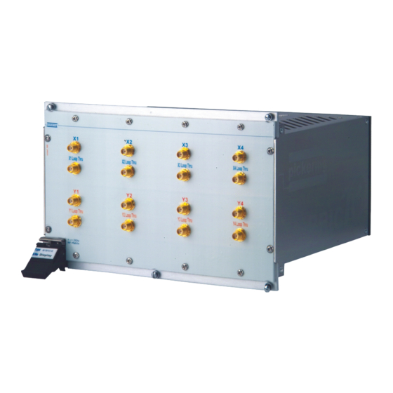
- Page 1 User Manual BRIC Microwave Matrix Module (Model No. 40-787) Issue 4.1 May 2017 pickeringtest.com pickering BRIC MICROWAVE MATRIX MODULE 40-787 Page (1)
- Page 2 © COPYRIGHT (2017) PICKERING INTERFACES. ALL RIGHTS RESERVED. No part of this publication may be reproduced, transmitted, transcribed, translated or stored in any form, or by any means without the written permission of Pickering Interfaces. Technical details contained within this publication are subject to change without notice.
- Page 3 Pickering Interfaces strives to fulfil all relevant environmental laws and regulations and reduce wastes and releases to the environment. Pickering Interfaces aims to design and operate products in a way that protects the environment and the health and safety of its employees, customers and the public. Pickering Interfaces endeavours to develop and manufacture products that can be produced, distributed, used and recycled, or disposed of, in a safe and environmentally friendly manner.
-
Page 4: Product Safety
PRODUCT SAFETY SAFETY SYMBOLS The following safety symbols may be used on the product and throughout the product documentation. MEANING / DESCRIPTION SYMBOL PROTECTIVE EARTH (GROUND) To identify any terminal which is intended for connection to an external conductor for protection against electric shock in case of a fault, or the terminal of a protective earth (ground) electrode. -
Page 5: Table Of Contents
Pre Operation Checks ............3.1 Hardware Installation ............3.2 Software Installation .............3.2 Testing Operation ..............3.3 Section 4 Programming Guide ..............4.1 Programming Options For Pickering PXI Cards....4.1 Module Architecture 40-787 ..........4.3 Programming Examples ............4.4 Section 5 Connector Information ..............5.1 Section 6 Trouble Shooting .................6.1 Section 7 Maintenance Information ............7.1... - Page 6 THIS PAGE INTENTIONALLY BLANK BRIC MICROWAVE MATRIX MODULE 40-787 Page (VI)
-
Page 7: Warnings And Cautions
Unused slots in the PXI/LXI chassis are populated with blanking plates to prevent access to user I/O signals that may be present. Blanking panels are available to order from Pickering in a variety of slot widths. If the product is not used in this manner for example by using an extender card then additional care must be taken to avoid contact with exposed signals. - Page 8 THIS PAGE INTENTIONALLY BLANK BRIC MICROWAVE MATRIX MODULE 40-787 Page (VIII)
-
Page 9: Technical Specification
Pickering Interfaces 40-908. ● 3 Year Warranty If you have an application requiring higher frequencies, more functionality or a larger matrix Pickering Interfaces can adapt the design of the this module to your The 40-787 Microwave BRIC platform is designed to requirements. - Page 10 SECTION 1 - TECHNICAL SPECIFICATION pickering Termination Switches Termination Switches Termination Switches 4 x 4 4 x 4 MICROWAVE MICROWAVE MATRIX MATRIX 4 x 4 MICROWAVE Loop Thru Switches Loop Thru Switches MATRIX Termination Switches Termination Switches Loop Thru Switches...
- Page 11 SECTION 1 - TECHNICAL SPECIFICATION pickering Figure 1.1 - Plot: SWR at X1 Terminated Figure 1.2 - Plot: SWR at X1 Y1 Terminated BRIC MICROWAVE MATRIX MODULE 40-787 Page 1.3...
- Page 12 SECTION 1 - TECHNICAL SPECIFICATION pickering Figure 1.3 - Plot: Output at X2 Y2 Figure 1.4 - Plot: Output at X3 LT BRIC MICROWAVE MATRIX MODULE 40-787 Page 1.4...
- Page 13 All modules are fully CE compliant and meet applicable EU Systems such as LabVIEW RT. For other RTOS support directives: Low-voltage safety EN61010-1:2001, contact Pickering. These drivers may be used with a variety of EMC Immunity EN61000-6-1:2001, Emissions EN55011:1998. programming environments and applications including: —...
- Page 14 SECTION 1 - TECHNICAL SPECIFICATION pickering THIS PAGE INTENTIONALLY BLANK BRIC MICROWAVE MATRIX MODULE 40-787 Page 1.6...
-
Page 15: Functional Description
SECTION 2 - TECHNICAL DESCRIPTION pickering SECTION 2 - TECHNICAL DESCRIPTION FUNCTIONAL DESCRIPTION A functional block diagram is provided in Figure 2.1. The BRIC Microwave Matrix Module is powered by +12V and +5V inputs via Compact PCI connector J1. The interface to the user test equipment is via the front panel SMA connectors. - Page 16 SECTION 2 - TECHNICAL DESCRIPTION pickering BANK 1 X1LT BANK 3 X2LT BANK 5 Relay Relay Relay Relay X3LT BANK 7 X4LT BANK 2 Y1LT BANK 4 Y2LT BANK 8 Y3LT BANK 6 Y4LT Figure 2.2 - Relay Interconnection BRIC MICROWAVE MATRIX MODULE 40-787...
-
Page 17: Installation
Modular products require installation in a suitable PXI/LXI chassis. The module is designed for indoor use only. PREOPERATION CHECKS (UNPACKING) 1. Check the module for transport damage and report any damage immediately to Pickering Interfaces. Do not attempt to install the product if any damage is evident. -
Page 18: Hardware Installation
For a system comprising more than one chassis, turn ON the last chassis in the system followed by the penultimate, etc, and finally turn ON the external controller or chassis containing the system controller. 9. For Pickering Interfaces modular LXI installation there is no requirement to use any particular power up sequence. -
Page 19: Testing Operation
Figure 3.2 - General Soft Front Panel Icon A selector panel will appear, listing all installed Pickering PCI, PXI or LXI switch cards and resistor cards. Click on the card you wish to control, and a graphical control panel is presented allowing operation of the card. - Page 20 SECTION 3 - INSTALLATION pickering THIS PAGE INTENTIONALLY BLANK BRIC MICROWAVE MATRIX MODULE 40-787 Page 3.4...
-
Page 21: Programming Guide
IVI Driver for Windows - pi40iv The pi40iv IVI (Interchangeable Virtual Instrument) driver supports all Pickering Interfaces PXI switch cards that are consistent with the Iviswtch class model - as are the great majority of cards in the System 40/45/50 ranges. It integrates well with LabWindows/CVI and LabVIEW, and is fully compatible with Switch Executive. - Page 22 Pickering LXI products include an SSH interface which allows remote command line access to control cards, or, using a suitable package, programmatic control. The user is advised to visit the Pickering web site for further details of all the above drivers, where documentation, example programs, and further help with driver choice are available.
-
Page 23: Module Architecture 40-787
SECTION 4 - PROGRAMMING GUIDE pickering MODULE ARCHITECTURE: 40-787 The 40-787 utilises up to eight 6 Channel Microwave switches depending on the option. In the default state no channels are connected. Energising the relays appropriately creates a signal path between the corresponding matrix terminals or Loop-Through connections. -
Page 24: Programming Examples
SECTION 4 - PROGRAMMING GUIDE pickering Programming Examples Refer to Figure 2.2 Note: Address is always 1 BANK 1 Example command for path X2 Y4 AD 1 3 (Address 1 BANK SC 3 (MUX output 3) BANK 3 BANK AD 1 8 (Address 1... -
Page 25: Connector Information
SECTION 5 - CONNECTOR INFORMATION pickering SECTION 5 - CONNECTOR INFORMATION Figure 5.1 provides Pin-outs for BRIC Microwave Matrix Module 40-787. X2 Loop Thru X3 Loop Thru X4 Loop Thru X1 Loop Thru Y2 Loop Thru Y3 Loop Thru Y4 Loop Thru Y1 Loop Thru Figure 5.1 - BRIC 4 x 4 LT Microwave Matrix Module: Connector Positions... - Page 26 SECTION 5 - CONNECTOR INFORMATION pickering THIS PAGE INTENTIONALLY BLANK BRIC MICROWAVE MATRIX MODULE 40-787 Page 5.2...
-
Page 27: Trouble Shooting
PCI configuration, highlighting any potential configuration problems. Specific details of all installed Pickering switch cards are included. All the installed Pickering switch cards should be listed in the “Pilpxi information” section - if one or more cards is missing it may be possible to determine the reason by referring to the PCI configuration dump contained in the report, but interpretation of this information is far from straightforward, and the best course is to contact Pickering support: support@pickeringtest.com, if possible... - Page 28 SECTION 6 - TROUBLE SHOOTING pickering THIS PAGE INTENTIONALLY BLANK BRIC MICROWAVE MATRIX MODULE 40-787 Page 6.2...
-
Page 29: Maintenance Information
For PXI modules which are supported in one of Pickering Interfaces’ Modular LXI Chassis (such as the 60-102B and 60-103B) no module software update is required. If the module was introduced after the LXI chassis was manufactured the module may not be recognized, in this case the chassis firmware may need upgrading. - Page 30 SECTION 7 - MAINTENANCE INFORMATION pickering TABLE 7.1 - Matrix Module: Relay Numbering MATRIX CROSSPOINT TO MICROWAVE RELAY CONNECTIONS: CROSS REFERENCE TABLE - 4 x 4 CONFIGURATION Output Internal Relay Output Internal Relay Bank Relay Bank Relay Connection Connection Connection...
- Page 31 SECTION 7 - MAINTENANCE INFORMATION pickering Figure 7.3- BRIC Backplane: Component Layout BRIC MICROWAVE MATRIX MODULE 40-787 Page 7.3...
- Page 32 SECTION 7 - MAINTENANCE INFORMATION pickering Figure 7.4 - BRIC Microwave Matrix: Front Panel Sub-Assembly X1LT X2LT X3LT X4LT Y1LT Y2LT Y3LT Y4LT Figure 7.5 - Microwave Relay: Wired Connections BRIC MICROWAVE MATRIX MODULE 40-787 Page 7.4...
Need help?
Do you have a question about the PXI 40-787 and is the answer not in the manual?
Questions and answers