
Related Manuals for Pickering PXI 40-785


Summary of Contents for Pickering PXI 40-785
- Page 1 (217) 352-9330 | Click HERE Find the Pickering 40-785-521-T at our website:...
- Page 2 User Manual PXI Microwave Multiplexer Module (Model No. 40-785) Issue 3.2 August 2019 pickeringtest.com pickering MICROWAVE MULTIPLEXER MODULE 40-785 Page (1)
- Page 3 © COPYRIGHT (2019) PICKERING INTERFACES. ALL RIGHTS RESERVED. No part of this publication may be reproduced, transmitted, transcribed, translated or stored in any form, or by any means without the written permission of Pickering Interfaces. Technical details contained within this publication are subject to change without notice.
- Page 4 Pickering Interfaces strives to fulfil all relevant environmental laws and regulations and reduce wastes and releases to the environment. Pickering Interfaces aims to design and operate products in a way that protects the environment and the health and safety of its employees, customers and the public. Pickering Interfaces endeavours to develop and manufacture products that can be produced, distributed, used and recycled, or disposed of, in a safe and environmentally friendly manner.
-
Page 5: Product Safety
PRODUCT SAFETY SAFETY SYMBOLS The following safety symbols may be used on the product and throughout the product documentation. MEANING / DESCRIPTION SYMBOL PROTECTIVE EARTH (GROUND) To identify any terminal which is intended for connection to an external conductor for protection against electric shock in case of a fault, or the terminal of a protective earth (ground) electrode. -
Page 6: Table Of Contents
Installation ..................3.1 Pre Operation Checks ............3.1 Hardware Installation ............3.2 Software Installation .............3.2 Testing Operation ..............3.3 Section 4 Programming Guide ..............4.1 Programming Options For Pickering PXI Cards....4.1 Section 5 Connector Information ..............5.1 Section 6 Trouble Shooting .................6.1 Section 7 Maintenance Information ............7.1 Component Layout ..............7.2... - Page 7 THIS PAGE INTENTIONALLY BLANK MICROWAVE MULTIPLEXER MODULE 40-785 Page (VI)
-
Page 8: Warnings And Cautions
Not to be used in safety critical circuits, refer to the Pickering Interfaces’ terms & conditions of sale. This module must not be used for the switching of Mains Circuits. For the switching of voltages up to the module’s full specification, Secondary Circuit power supplies and the Device Under Test must... - Page 9 CAUTION - PRODUCT DOCUMENTATION SYMBOL Suitably qualified & trained users should ensure that the accompanying documentation is fully read and understood before attempting to install or operate the product. SAFETY INSTRUCTIONS SAFETY INSTRUCTIONS All cleaning and servicing requires the equipment to be isolated and disconnected from the power source and user I/O signals (refer to the Maintenance Section).
- Page 10 50Ω versions. These modules give you the highest RF and microwave switching performance available within a Pickering switching system. Although designed for microwave applications, they have many uses in the RF spectrum where extremely low insertion loss and ultra high isolation are critical.
- Page 11 SECTION 1 - TECHNICAL SPECIFICATION pickering Specifications Microwave Multiplexer – 40-785 Specification - 18GHz Version Switching Specification - Un-terminated 26.5GHz Version Characteristic Impedance: 50Ω Insertion Loss: <0.7dB VSWR: <1:1.7 Maximum Frequency: 18GHz Isolation: >50dB Rise Time: <3ps Expected Life: 5x10...
- Page 12 40-785-752 Product Customization Single 6 Chan, Remote mount, 75Ω 1.6/5.6 40-785-751-E Pickering PXI modules are designed and manufactured on our own Dual 6 Chan, Remote mount, 75Ω 1.6/5.6 40-785-752-E flexible manufacturing lines, giving complete product control and Triple 6 Chan, Remote mount, 75Ω 1.6/5.6 40-785-753-E enabling simple customization to meet very specific requirements.
- Page 13 We provide a full range of supporting cable and connector solutions for all our switching products—20 connector families with 1200+ products. We offer everything from simple mating connectors to complex cables assemblies and terminal blocks. All assemblies are manufactured by Pickering and are guaranteed to mechanically and electrically mate to our modules. Connectors & Backshells...
- Page 14 Microwave Multiplexer – 40-785 Programming Pickering provide kernel, IVI and VISA (NI & Keysight) drivers which are compatible with all Microsoft supported versions of Windows and popular older versions. For a list of all supporting operating systems, please see: pickeringtest.com/os The VISA driver is also compatible with Real-Time Operating Systems such as LabVIEW RT.
- Page 15 SECTION 1 - TECHNICAL SPECIFICATION pickering THIS PAGE INTENTIONALLY BLANK MICROWAVE MULTIPLEXER MODULE 40-785 Page 1.6...
-
Page 16: Technical Description
SECTION 2 - TECHNICAL DESCRIPTION pickering SECTION 2 - TECHNICAL DESCRIPTION MECHANICAL DESCRIPTION The Microwave Multiplexer Module conforms to the 3U height (128mm) Eurocard standard and comprises the following: • CPCI Ejector Handle • Three, four or six slot width Front Panel (single slot for the remote -E option) •... -
Page 17: Functional Description
SECTION 2 - TECHNICAL DESCRIPTION pickering FUNCTIONAL DESCRIPTION A functional block diagram is provided in Figure 2.2. The Microwave Multiplexer Module is powered by +12V and +5V inputs via Compact PCI connector J1. The interface to the user test equipment is via the front panel mounted SMA connectors. -
Page 18: Installation
Modular products require installation in a suitable PXI/LXI chassis. The module is designed for indoor use only. PREOPERATION CHECKS (UNPACKING) 1. Check the module for transport damage and report any damage immediately to Pickering Interfaces. Do not attempt to install the product if any damage is evident. -
Page 19: Hardware Installation
For a system comprising more than one chassis, turn ON the last chassis in the system followed by the penultimate, etc, and finally turn ON the external controller or chassis containing the system controller. 9. For Pickering Interfaces modular LXI installation there is no requirement to use any particular power up sequence. -
Page 20: Testing Operation
Figure 3.2 - General Soft Front Panel Icon A selector panel will appear, listing all installed Pickering PCI, PXI or LXI switch cards and resistor cards. Click on the card you wish to control, and a graphical control panel is presented allowing operation of the card. - Page 21 SECTION 3 - INSTALLATION pickering THIS PAGE INTENTIONALLY BLANK MICROWAVE MULTIPLEXER MODULE 40-785 Page 3.4...
-
Page 22: Programming Guide
SECTION 4 - PROGRAMMING GUIDE PROGRAMMING OPTIONS FOR PICKERING INTERFACES PXI MODULES For information on the installation and use of drivers and the programming of Pickering’s products in various software environments, please refer to the Software User Manual. This is available as a download from: https://www.pickeringtest.com/support/software-drivers-and-downloads... - Page 23 SECTION 4 - PROGRAMMING GUIDE pickering THIS PAGE INTENTIONALLY BLANK MICROWAVE MULTIPLEXER MODULE 40-785 Page 4.2...
-
Page 24: Connector Information
SECTION 5 - CONNECTOR INFORMATION pickering SECTION 5 - CONNECTOR INFORMATION pickering pickering pickering 40-785-521/751 40-785-522/752 40-785 Remote Version (-E Suffix) Figure 5.1 - Microwave Multiplexer Module 40-785: Connector Positions pickering pickering NOTE 1: Only the correct SMA connector series should be mated with these modules. The 40-785 range uses SMA-3.5, SMA-2.9 &... - Page 25 SECTION 5 - CONNECTOR INFORMATION pickering 40-785-521/751 40-785-522/752 40-785 Remote Version (-E Suffix) pickering pickering 40-785-521-T 40-785-522-T Figure 5.2 - Microwave Multiplexer Module 40-785: Connector Positions MICROWAVE MULTIPLEXER MODULE 40-785 Page 5.2...
-
Page 26: Trouble Shooting
PCI configuration, highlighting any potential configuration problems. Specific details of all installed Pickering switch cards are included. All the installed Pickering switch cards should be listed in the “Pilpxi information” section - if one or more cards is missing it may be possible to determine the reason by referring to the PCI configuration dump contained in the report, but interpretation of this information is far from straightforward, and the best course is to contact Pickering support: support@pickeringtest.com, if possible... - Page 27 SECTION 6 - TROUBLE SHOOTING pickering THIS PAGE INTENTIONALLY BLANK MICROWAVE MULTIPLEXER MODULE 40-785 Page 6.2...
-
Page 28: Maintenance Information
For PXI modules which are supported in one of Pickering Interfaces’ Modular LXI Chassis (such as the 60-102B and 60-103B) no module software update is required. If the module was introduced after the LXI chassis was manufactured the module may not be recognized, in this case the chassis firmware may need upgrading. -
Page 29: Component Layout
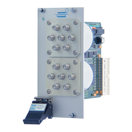
SECTION 7 - MAINTENANCE INFORMATION pickering COMPONENT LAYOUT 201r0 06/00 Figure 7.1 - Microwave Multiplexer Module 40-785: Component Layout MICROWAVE MULTIPLEXER MODULE 40-785 Page 7.2... - Page 30 SECTION 7 - MAINTENANCE INFORMATION pickering Figure 7.2 - Dual 6-Channel Multiplexer in Panel Mount Format Figure 7.3 - Triple 6-Channel Multiplexer in Remote Mount Format (Multiplexers are connected to the module via supplied interface cables) MICROWAVE MULTIPLEXER MODULE 40-785...
- Page 31 SECTION 7 - MAINTENANCE INFORMATION pickering THIS PAGE INTENTIONALLY BLANK MICROWAVE MULTIPLEXER MODULE 40-785 Page 7.4...
Need help?
Do you have a question about the PXI 40-785 and is the answer not in the manual?
Questions and answers