
Subscribe to Our Youtube Channel
Related Manuals for Garland Master Xpress XE241L


Summary of Contents for Garland Master Xpress XE241L
- Page 1 Master Series Electric Xpress Grills Installation, Operation and Maintenance Manual models XE24 XE241L XE241R XE36 XE362L XE362R XE361C XE361L XE361R Original Instructions Part # 4517125 Rev. 3 (18 May 16)
-
Page 2: Safety Notices
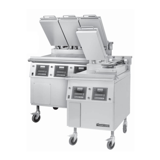
POWER CORDS. INTRODUCTION The Garland Xpress Grill provides a method for effi cient two-sided cooking, while accommodating a variety of products. The unit will also serve as a fl at grill, and meets all standards for safety, effi ciency, and cleanliness. -
Page 3: Table Of Contents
DIMENSIONS AND SPECIFICATIONS, MODEL XE24 ..4 To View the Garland Part Number: ..... 22 To View the Software Number:. -
Page 4: Dimensions And Specifications, Model Xe24
DIMENSIONS AND SPECIFICATIONS, MODEL XE24 26-23/32" [678mm] FROM PLATEN 25-1/2" ARM PIVOT [646mm] AVERAGE 11-1/2" 4-41/64" [292mm] [118mm] 28-3/16" 23" HEATER [716mm] [584mm] 44.03° TOP VIEW (2 PLACES) 50-1/2" AVERAGE [1282mm] [48° MAX] AVERAGE 24" 33-25/32" [610mm] 38-1/2" [858mm] 25-7/8" GRILL [978mm] [656mm]... -
Page 5: Dimensions And Specifications, Model Xe36
DIMENSIONS AND SPECIFICATIONS, MODEL XE36 26-23/32" [678mm] FROM PLATEN 25-1/2" ARM PIVOT [646mm] AVERAGE 4-41/64" 11-1/2" [118mm] 40-3/16" [292mm] 23" [1021mm] TOP HEATER [584mm] 44.03° (3 PLACES) TOP VIEW 50-1/2" AVERAGE [1282mm] [48° MAX] AVERAGE 33-25/32" [858mm] 25-7/8" 38-1/2" 24" [656mm] [978mm] [610mm]... -
Page 6: Safety Precautions
Suitable protective access panels are in place and fastened properly. clothing should be worn to prevent the risk of burns. The Garland Xpress Grill is a semi-automatic cooking • DO NOT clean this appliance with a water jet. -
Page 7: Installation
INSTALLATION IMPORTANT: Rating plate for this appliance is located on The grill is to be located directly under ventilation system. the right side panel. Once installed in the grill station underneath the ventilation This equipment must be installed by a competent factory system, the platens, in their highest position, must not trained, certifi ed, licensed and / or authorized service or interfere with the lower lip of the ventilation system hood. -
Page 8: Grill Controls
GRILL CONTROLS WHEN PUSHED SIMULTANEOUSLY: "START COOK TIME COUNTDOWN" (flat grill cooking) OR "LOWER PLATEN" (two-sided cooking) 16-CHARACTER INDICATORS 2-LINE DISPLAY CANCEL/ RAISE PLATEN BUTTON PRODUCT MASTER BUTTONS POWER SWITCH POWER ENTER BUTTON BUTTON PROGRAM DOWN ARROW BUTTON BUTTON TEMPERATURE UP ARROW BUTTON BUTTON... -
Page 9: Temperature Button
GRILL CONTROLS continued Temperature Button: Enter Button: In the Cook mode, each time the button is pressed the Function is to accept programming steps. current temperature for one zone is displayed. The grill Cancel/Raise Platen Button, (Green): temperature is displayed fi rst followed by the platen temperature. -
Page 10: Operation
OPERATION Installing Release Material: RELEASE MATERIAL A release material sheet must be replaced when: RELEASE • Product sticks to release material. MATERIAL • Carbon build-up ruins taste or appearance. LOCKING CLIP (1) • Tearing occurs in the sheet’s cooking area. •... -
Page 11: Simplifi Ed Cook Cycle Instructions
OPERATION continued 5. Press green button to cancel any time during cook cycle. Simplifi ed Cook Cycle Instructions: 1. Press button to turn on mainpower to grill. To Cook in Two-Sided Mode: 1. To start a cook cycle select a product recipe by using the 2. -
Page 12: To Cook In Flat Grill Mode
OPERATION continued To Cook in Flat Grill Mode: Enter Standby Mode: 1. To start a cook cycle select a product recipe by using the Stand by mode is used during slow periods to conserve product keys (1 through 9) or by using the UP/DOWN energy with out a complete shut down of the unit. -
Page 13: Cleaning And Maintenance
OPERATION continued EXTENDED TIME: 3. Press the ENTER key to initiate the clean mode. This option will add 6, 4 and 2 seconds to the time of the next 4. The display SHOWS the message “READY TO CLEAN” with three cooks respectively if the grill has had no activity for fl ashing in the second line when the actual temperature 5 minutes. - Page 14 CLEANING AND MAINTENANCE continued • Select Clean Mode • Remove the locking clips, • Scrape the lower grill • Wipe the Release When Clean Mode has bars, and release sheets. surface with the scraper. Material sheets with a Wash, rinse, and set aside been reached, the LED clean,sanitizer-soaked •...
- Page 15 CLEANING AND MAINTENANCE continued • Rinse the edges of all three • Place upper platen • Rinse both sides of • Pour a small amount of platens. release material sheets the release material lukewarm water on a fl at on the lower grill sheets with a clean, clean, sanitizer-soaked •...
-
Page 16: Platen Zeroing
PLATEN ZEROING Turn Master power switch “ON”, wait for controllers to display 8. Using the adjusting tool lower platen until adjusting tool “OFF”. touches the arm assembly. Note: Release sheets should not be installed during this 9. With gapping tool, adjust right rear of platen until the procedure. -
Page 17: Accessories
ACCESSORIES Teflon Release Material Rod - 4517008 (one per platen; 3 shown) Teflon Release Material Sheet - 1799303 (one per platen) Teflon Release Material Clip - 1851301 (one per platen; 3 shown) Grill Squeegee - 1868201 Platen Gapping Tool -1838701 “No-Go”... - Page 18 ACCESSORIES continued Platen Adjusting Tool - 4523323 Platen leveling should be done from one corner to the opposite corner. The adjuster nuts should be turned opposite of one another. Use this end to turn all slotted adjuster caps and nuts Platen Adjuster Cap - 1859102 Platen Adj Lock Nut - 1859103 Shoulder Bolt - 4527290...
-
Page 19: Programming
PROGRAMMING Programming Modes/Menu Sequence: System Information Part # 4517125 Rev. 3 (18 May 16) Page 19... - Page 20 PROGRAMMING continued System Set-up UPPER SET TEMP GRILL SET TEMP Service Mode PLATEN GAP SET Page 20 Part # 4517125 Rev. 3 (18 May 16)
-
Page 21: Menu Items
PROGRAMMING continued Menu Items... 5. Use to choose the desired Menu Item. 6 Press three, (3) times to display “(MENU ITEM) UPPER To Change the Cook Time of a Product: TEMP XXX” displayed in °F or °C. 1. Press and hold for three, (3) seconds. -
Page 22: To Change Product Button, "Key" Assignment
SYSTEM INFO. ” 8. Press to save the changes. You will automatically 5. Press three, (3), times to view the Garland Part Number return to “PROGRAMMING MODE MENU ITEMS”. for the grill. “GARLAND PART # X…X” is displayed. (number varies by grill). -
Page 23: To View The Software Number
PROGRAMMING continued To View the Flash Number: number varies by grill). 6. Press to return to “PROGRAMMING MODE SYSTEM 1. Press and hold for three, (3) seconds. “ENTER CODE” is INFO”. displayed. 7. Press to exit. 2. Using the Product buttons, 0-9 enter the code, (1251). “ENTER CODE **** ”... -
Page 24: To Change The Alarm Volume
PROGRAMMING continued To Change the Alarm Volume: 3. Press to enter the Programming Mode. “PROGRAMMING MODE MENU ITEMS” is displayed. 1. Press and hold for three, (3) seconds. “ENTER CODE” is displayed. 4. Press two, (2) times. “PROGRAMMING MODE SYSTEM SETUP”... -
Page 25: To Change Probe Calibration - Grill
PROGRAMMING continued 2. Using the Product buttons, 0-9 enter the code, (1251). 5. Press five, (5), times. “PROBE CAL – UPPER XXXF” is “ENTER CODE **** ” is displayed. displayed. 3. Press to enter the Programming Mode. 6. Use to change the Probe Calibration to the “PROGRAMMING MODE MENU ITEMS”... -
Page 26: To Turn Extended Time On/Off
PROGRAMMING continued “PROGRAMMING MODE MENU ITEMS” is displayed. Clamshell mode. 4. Press two, (2) times. “PROGRAMMING MODE SYSTEM 7. Press to save the changes. SETUP” is displayed. 8. Press to return to “PROGRAMMING MODE MENU 5. Press eleven, (11) times. “CONTROL TYPE ELECTRIC (or ITEMS”... -
Page 27: To Turn Clean Mode On/Off
PROGRAMMING continued LIB” is displayed. 8. Press to return to “PROGRAMMING MODE MENU ITEMS” 10. Press to exit. 9. Press again to exit. To Modify a Product Name in Library: To Turn Clean Mode On/Off : 1. Press and hold for three, (3) seconds. -
Page 28: To Perform Limit Switch Test
PROGRAMMING continued 9. Press again to exit. 5. Press two, (2), times. “PLATEN” (along with the position of each switch), is displayed. To Perform Limit Switch Test: 6. Use to move the platen up and down. Check 1. Press and hold for three, (3) seconds. -
Page 29: Probe Locations
CALIBRATION continued Probe Locations: The grill’s thermocouple probes are located on each section of the lower grill plate in the center of the cooking zone as shown in the diagram below. Each upper platen has one thermocouple probe in the center. 11.5"... -
Page 30: Error Logic & Troubleshooting
ERRORS & TROUBLESHOOTING Probe Error Heating Error Occurs when the probe Occurs the controller is open or not connected. will fails to detect a The controller will turn temperature response the heat off . over a 6-minute period. Grill & Grill &... -
Page 31: Platen Down Error
ERRORS & TROUBLESHOOTING continued Platen Down Error Gas Ignition Error Motor Overcurrent Error Occurs when current to the motor Occurs at cycle-start when the Occurs when the ignition exceeds 4.8 amps, typically because platen fails to reach lower limit feedback signal does not platen movement has encountered position within 40 sec. -
Page 32: Motor Error2
ERRORS & TROUBLESHOOTING continued Motor Error2 Lower Switch Error Upper Switch Error Occurs when the platen is in motion Occurs at cycle start when the Appears in code, and fails to reach the upper or lower lower limit switch fails to signal the but is never set. -
Page 33: Wiring Diagrams Xe24
WIRING DIAGRAMS XE24 Part # 4517125 Rev. 3 (18 May 16) Page 33... -
Page 34: Wiring Diagrams Xe36
WIRING DIAGRAMS XE36 Page 34 Part # 4517125 Rev. 3 (18 May 16) - Page 35 To learn how Manitowoc Foodservice and its leading brands can equip you, visit our global web site at www.manitowocfoodservice.com, then discover the regional or local resources available to you. ©2009 Garland Commercial Industries, Inc. ©2014 Manitowoc Foodservice except where explicitly stated otherwise. All rights reserved.
- Page 38 MAIN SWITCH 240V 120V PLATEN RED PLATEN YELL GRIDDLE RED GRIDDLE YELLOW ACTUATOR...
Need help?
Do you have a question about the Master Xpress XE241L and is the answer not in the manual?
Questions and answers