Table of Contents
Advertisement
Quick Links
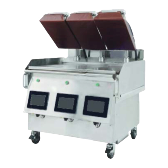
Electric/Gas Dual Side Xpress Grill
Models:
XP(E/G)12
XP(E/G)24, XP(E/G)24-1(L/R)
XP(E/G)36, XP(E/G)36-2(L/R)
Installation, Operation and Maintenance Manual
Please read all sections of this manual and retain for future reference.
For your safety:
Post in a prominent location, instructions to be followed
in the event the user smell gas. This information shall be
obtained by consulting your local gas supplier.
XP(E/G)12 Shown
Original Instructions
Part #: GAR_IOM_ 4532522 Rev 08—6/17
XP(E/G)24 Shown
XP(E/G)36 Shown
Advertisement
Table of Contents

Related Manuals for Garland XPE12


Summary of Contents for Garland XPE12
- Page 1 Electric/Gas Dual Side Xpress Grill Models: XP(E/G)12 XP(E/G)24, XP(E/G)24-1(L/R) XP(E/G)36, XP(E/G)36-2(L/R) Installation, Operation and Maintenance Manual Please read all sections of this manual and retain for future reference. For your safety: Post in a prominent location, instructions to be followed in the event the user smell gas.
- Page 2 THIS PAGE INTENTIONALLY LEFT BLANK...
-
Page 3: Definitions
Safety Notices DANGER It is the responsibility of the equipment owner to DEFINITIONS perform a Personal Protective Equipment Hazard Assessment to ensure adequate protection during DANGER maintenance procedures. Indicates a hazardous situation that, if not avoided, will result in death or serious injury. This applies to the most DANGER extreme situations. -
Page 4: Location
ELECTRICAL Warning This product contains chemicals known to the State DANGER of California to cause cancer and/or birth defects or Check all wiring connections, including factory other reproductive harm. Operation, installation, and terminals, before operation. Connections can become servicing of this product could expose you to airborne loose during shipment and installation. -
Page 5: Damage
CODE CLEARANCE Caution Warning Do not block the supply and return air vents or the air Authorized Service Representatives are obligated to space around the air vents. Keep plastic wrappings, follow industry standard safety procedures, including, paper, labels, etc. from being airborne and lodging in but not limited to, local/national regulations for the vents. - Page 6 CLEANING Warning Caution Be aware that adjacent platens may unexpectedly move at any time. “Turn Grill Off” at main switch when cleaning Ensure platens are down, in closed position, when platens as there can be an unexpected movement of the moving grill.
- Page 7 Warning Warning Remove all removable panels before lifting and This appliance must be installed with sufficient installing. ventilation to prevent the occurrence of unacceptable concentrations of substances harmful to the health of Warning personnel in the room in which it is installed. Do not contact moving parts.
-
Page 8: Table Of Contents
Table of Contents Safety Notices Definitions..............................3 Disclaimers ..............................3 Location ..............................4 Electrical ..............................4 Damage..............................5 Clearance ..............................5 Section 1 General Information Read This Manual ......................10 Unit Inspection .........................10 Model Numbers ........................10 Serial Plate Numbers ......................10 Warranty Statement ......................11 Main Features and Components ..................12 Items included with the purchase of your new grill from manufacturer: ....13 3 Platen Dimensions Specification .................14 2 Platen Dimensions Specification .................15... - Page 9 Table of Contents (continued) Operation Sequence of Operation ....................39 easyToUCH™ Controller ....................40 Home Screen, Recipe Selector Screen & Icons ................. 40 On Screen Warnings and Alerts Messages ................. 41 Operations Overview ......................... 41 easyTOUCH™ Procedures ....................42 Start Up & Preheat ..........................42 Cook A Recipe ............................
-
Page 10: General Information
Section 1 General Information Read This Manual Model Numbers Garland Commercial Equipment developed this manual as This manual covers the following models: a reference guide for the owner/operator and installer of XP(E/G)12 this equipment. Please read this manual before installation XP(E/G)24, XP(E/G)24-1(L/R) or operation of the machine. -
Page 11: Warranty Statement
(ii) at Garland’s option, the refund of the amount paid for said equipment product and is not transferable. or services. Any breach by Garland with respect to any item or unit of equipment or services XCLUSIONS OVERAGE shall be deemed a breach with respect to that item or unit or service only. -
Page 12: Main Features And Components
General Information Section 1 Main Features and Components 1. On/Off Power Switch. 10. Platen - providing double-side cooking. Each platen can be controlled separately. 2. easyToUCH™ Touch sensitive controls for easy operation. 11. Grill Plate - cooking surface with three (3) Independently 3. -
Page 13: Items Included With The Purchase Of Your New Grill From Manufacturer
4600208 Grease Drawer Slide RT - GM • A licensed installer contracted by purchaser of grill. 1838701 Platen Levelling Tool Contact local Garland Factory Authorized Service Center 4532089 Service Wrench for more details. 4601665 Garland Grill Start Up Form CAUTION:... -
Page 14: Platen Dimensions Specification
General Information Section 1 3 Platen Dimensions Specification Dimensions: model: XP(E/G)36 PLATEN WIDTH 11.500in SHOWN WITH LEFT PLATEN REMOVED 292mm GREASE DRAWER LENGTH 5.625in 31.437in 143mm OVERALL 798mm GRILL PLATE DEPTH DEPTH 34.503in 22.000in 876mm 559mm COOK ZONE DEPTH PLATEN 19.750in 31.512in LENGTH... -
Page 15: Platen Dimensions Specification
Section 1 General Information 2 Platen Dimensions Specification Dimensions: model: XP(E/G)24 PLATEN WIDTH 11.500in SHOWN WITH LEFT PLATEN REMOVED 292mm GREASE DRAWER 5.625in LENGTH 143mm OVERALL 31.437in GRILL PLATE DEPTH 798mm DEPTH 34.503in 22.000in 876mm COOK ZONE 559mm DEPTH 19.750in PLATEN 31.512in LENGTH... -
Page 16: Platen Dimensions Specification
General Information Section 1 1 Platen Dimensions Specification Dimensions: model: XP(E/G)12 PLATEN WIDTH 11.500in 292mm SHOWN WITH PLATEN REMOVED 5.625in GREASE DRAWER OVERALL LENGTH 143mm DEPTH GRILL PLATE 31.437in 36.628in DEPTH 798mm 930mm 22.000in COOK ZONE 559mm DEPTH 31.512in PLATEN 19.750in LENGTH 800mm... -
Page 17: Electrical Input Specification - Wye (Electric Models)
Section 1 General Information Electrical Input Specification - WYE (Electric models) Part #: GAR_IOM_ 4532522 Rev 08—6/17... -
Page 18: Electrical Input Specification - Delta (Electric Models)
General Information Section 1 Electrical Input Specification - DELTA (Electric models) Part #: GAR_IOM_ 4532522 Rev 08—6/17... - Page 19 Section 1 General Information Electrical Input Specification - DELTA (Electric models), continuation Part #: GAR_IOM_ 4532522 Rev 08—6/17...
-
Page 20: Electrical Input Specification - Wye (Gas Xpg-12-Ce Models)
General Information Section 1 Electrical Input Specification - WYE (gas XPG-12-CE models) XPG-12 CE Models (gas models) XPG-12 (0L/R) CE Models (gas models) Volts Volts Total Current (A) Total Current (A) Model Model 3N (WYE) Power(kW) 3N (WYE) Power(kW) 50/60Hz 50/60Hz 220V/380V 12.6... -
Page 21: Electrical Input Specification - Wye (Gas Xpg-24 Ce Models)
Section 1 General Information Electrical Input Specification - WYE (gas XPG-24 CE models) XPG-24 CE Models (gas models) XPG-24 (0L,0R) CE Models (gas models) Volts Volts Total Current (A) Total Current (A) Model Model 3N (WYE) Power(kW) 3N (WYE) Power(kW) 50/60Hz 50/60Hz 220V/380V... -
Page 22: Electrical Input Specification - Delta (Gas Xpg-36 Models)
General Information Section 1 Electrical Input Specification - WYE (gas XPG-36 CE models) XPG-36 CE Models (gas models) XPG-36 (0L/R) CE Models (gas models) Volts Volts Total Current (A) Total Current (A) Model Model 3N (WYE) Power(kW) 3N (WYE) Power(kW) 50/60Hz 50/60Hz 220V/380V... - Page 23 Section 1 General Information Electrical Input Specification - DELTA (gas XPG-36 models), continuation XPG-36 1L Models (gas models) XPG-36 1R Models (gas models) Volts Volts Total Current (A) Total Current (A) Model Model 3 (WYE) Power(kW) 3 (WYE) Power(kW) 50/60Hz 50/60Hz 200V 20.6...
-
Page 24: Gas Input Specification
General Information Section 1 Gas Input Specification STANDARD GAS SETTINGS/SPECIFICATIONS FOR CSA APPROVED MODELS STANDARD PRESSURE SWITCH INPUT/ "TOTAL INPUT/UNIT SUPPLY MANIFOLD INJECTOR ELEVATION SPEED SETTING BURNER BTU" PRESSURE PRESSURE SIZE GAS TYPE " W.C. Colour 12in 24in 36in FEET "... -
Page 25: Gas Elevations Settings
Section 1 General Information Determining Unit Configuration for Gas Grills continuation: b. If the grill has been supplied with the following label, it has been configured for high elevation. The elevation and gas type for the unit is indicated by the punched hole in the “Appliance Set For” section. For example, on the label shown below, the unit is configured for Natural gas between 7001 and 9500 feet (2135 and 2896 meters). - Page 26 General Information Section 1 Gas Elevations Settings continuation: HIGH ELEVATION GAS SETTINGS/SPECIFICATIONS FOR CE APPROVED MODELS ELEVATION PRESSURE ¹INPUT/ ²TOTAL INPUT/UNIT SUPPLY MANIFOLD INJECTOR RANGE SPEED SWITCH SETTING BURNER PRESSURE PRESSURE SIZE GAS TYPE " W.C. Colour 12in 24in 36in METERS mbar mbar...
- Page 27 Section 1 General Information CE APPROVED CONVERSION KITS FOR ELEVATION CONVERSION KIT #4602237 FOR ALL CE APPROVED 12in UNITS THIS KIT IS USED TO CONVERT 12in CE APPROVED STANDARD SEA LEVEL UNITS TO HIGH ELEVATION UNITS. THIS KIT ONLY APPLIES TO 12in GRILLS, CONFIGURED FOR USE WITH G20 NATURAL GAS AND G31 PROPANE GAS.
-
Page 28: Conversion Labels
General Information Section 1 Conversion Labels: For CSA + CE conversion kits for elevation → For CE conversion kit G20 to G25 → For CE conversion kit for G25 to G20 → Part #: GAR_IOM_ 4532522 Rev 08—6/17... -
Page 29: Installation
Section 2 Installation STOP! - Follow the instructions below to safely and easily remove unit from packaging skid. Unit very heavy Personal Protective Equipment (PPE) required. Removing Grill From Wood Crate 3. REMOVE AND DISCARD THE TWO (2) WOOD BLOCKS LOCKING EACH OF THE FRONT CASTER. NOTE: ENSURE FRONT CASTER BRAKES ARE ON Tools required. -
Page 30: Transporting Grill To Location
Installation Section 2 Transporting Grill To Location • The location must not be near heat-generating (broiler, dishwashers, etc) equipment or in direct sunlight and Transporting your new grill to the kitchen requires the must be protected from weather. following criteria. •... -
Page 31: Appliances Equipped With Casters
The front and rear casters are adjustable, only the front casters have brakes. Garland recommends installing restraining chains/cables from the floor/wall to the rear of the unit. These restraints limit the mobility of the appliance. A restraining cable must be used for gas units connected with a flexible gas hose. -
Page 32: Temporary Storage
REAR CASTER WITHOUT BRAKE stainless steel. Temporary Storage Garland provides adequate protection under normal conditions in transit and storage. The grill may need additional protection if it is stored near salt water, a tropical area, or other unfavorable conditions. Please contact Garland immediately if these conditions occur. -
Page 33: National Codes Requirements
• The installation must conform to the National Fuel Gas • Contacting your local Garland Factory Authorized Code ANSI Z223.1-1998 or latest edition, NFPA No. 54 – Service Center for a startup date. latest edition and National Electrical Code ANSI/NFPA •... -
Page 34: Desi Pak" Bags From The Grill
• Garland highly recommends these bags remain in • Refer to “Gas Input Specification Chart” for correct the equipment while the grills are in storage or not in burner manifold pressure based on gas type. - Page 35 Section 2 Installation d. turn off the grill, remove the manometer and re- Electrical Connection fit the sealing screw on the pressure spigot and Warning regulator. e. test those connection for leaks. Disconnect power supply before starting this procedure. f.
-
Page 36: Flue Upper Rear Panel Install Instruction
Installation Section 2 Flue Upper Rear Panel Install Instruction Install flue box to the back of grill for all gas grill models only (if required). flue box assembly griddle rear backsplash Place hemmed flange of flue box over top edge of griddle rear backsplash Remove the flue assembly from the accessory box upper... - Page 37 Section 2 Installation Install Release Material Sheets 4. Gently pull the release material sheet towards (Rear Loop Option) the front platen and then In order to achieve proper cooking performance, ensure wrap the sheet around that the release material sheet is installed properly to the the front of platen and platen.
-
Page 38: Startup Procedure
230 VAC- 415 VAC- Y Ensure the grill is installed in accordance with Manitowoc /Garland manuals, mandatory, and local standards. INSPECTION / OPERATIONAL CHECK Ensure grill is installed under the correct type of exhaust hood with the minimum required air draw and height distance of approximately 24 inches (2 feet) from cooking surface. -
Page 39: Operation
Section 3 Operation NOTE: Do not operate the unit without reading and Wrong understanding the safety requirements. Refer to the safety Platen section at the front of this manual. Position Normal Open Sequence of Operation Normal After turning the power switch to “I” or ON position, the Platen Do Not Position... -
Page 40: Easytouch™ Controller
Operation Section 3 easyToUCH™ Controller PRESS & GO – is used to initiate preheat and cook on the grill. HOME SCREEN, RECIPE SELECTOR SCREEN & ICONS The easyToUCH™ HOME and RECIPE SELECTOR screens MENUS – is used to activate, add, edit and are the most frequently used screens. -
Page 41: On Screen Warnings And Alerts Messages
Section 3 Operation ON SCREEN WARNINGS AND ALERTS MESSAGES Menus and Recipes Too Cool/Too Hot - If the grill temperature is too cool to Multiple menus can be set up, each using different set properly cook a recipe, a “Too Cool to Cook” message point and containing different or share recipes. -
Page 42: Easytouch™ Procedures
Operation Section 3 easyTOUCH™ Procedures COOK A RECIPE 1. On the RECIPE START UP & PREHEAT SELECTOR screen, 1. Switch the grill on Green light select a recipe to using the main indicates cook. that the power switch. Grill power Lay product on is “ON”... -
Page 43: Check Temperatures
Section 3 Operation CHECK TEMPERATURES CHANGE COOK TIME/GAP The temperature screen shows the actual and the set point The changes made to a recipe in this procedure in the Press temperatures at each thermocouple. & Go mode will still apply after the power is turned off. A recipe’s cook time and gap can be modified to allow for 1. -
Page 44: Create New Recipe
Operation Section 3 CREATE NEW RECIPE The easyToUCH™ screen display, layout and icons shown herein are for guidance purposes only and are not intended to be an exact representation of those displayed on the grill. 1. A recipe consists of one or more steps. A step may end with a prompt such as 1. - Page 45 Section 3 Operation Editing an Existing Recipe Pressing the list icon will display the steps in the recipe available (screen shown below). Select the step with arrows editing, then press check. Press the pencil (top right of the screen) to edit an existing recipe.
-
Page 46: Setting Up For 2 Stage Cooking, "Add Cheese
Operation Section 3 SETTING UP FOR 2 STAGE COOKING, “ADD CHEESE” Prompt defi nition off er the option to add cheese or other product at the end of the cooking process, the platen will come up, cheese added and the platen will come down with at higher gap without touching this gives the cheese a head start toward reaching its melting point or warm any other product. -
Page 47: Create A New Menu
Section 3 Operation CREATE A NEW MENU Menus offer the option to combine many recipes under 6. Select an image one menu screen like breakfast, lunch and other menus and press the available through the day. check-mark to continue. 7. Select a recipe(s) 1. -
Page 48: Activate Sleep Mode Manually
Operation Section 3 ACTIVATE SLEEP MODE MANUALLY SHUTDOWN Sleep mode can be selected from the RECIPE SELECTOR 1. Return to the screen to save energy during slow periods. HOME screen. Pressing the Home 1. From the RECIPE icon exits cooking SELECTOR screen, mode and turns off press... -
Page 49: Special Settings - Time & Gap Adjustment Limits
Section 3 Operation SPECIAL SETTINGS — TIME & GAP ADJUSTMENT 6. Select to save LIMITS the new settings. This setting limits the size of the cook cycle adjustments that can be made for a recipe using Change Cook Time/ Gap. For example, if the time is set to 00:10, then the COOK CYCLE ADJUSTMENT screen will only allow the operator to increase or decrease the cook time by up to ten (10) seconds. -
Page 50: Hood Height Adjustment
Operation Section 3 HOOD HEIGHT ADJUSTMENT 6. Select APPLY This setting limits the height of the top platen adjustment. CALIBRATION Ensure a minimum of 1” clearance between the hood and to set the new the uppermost position of the platen arm. setpoint. -
Page 51: Clean Settings
Section 3 Operation 5. A save window will 4. Select an option, appears indicating numeric pad will that is saved. appear, enter new settings. 6. Language selection completed. System will go back • CLEAN GRILL – this option will confi gure the lower to settings. - Page 52 Operation Section 3 home page PRESSGO MENUS SETTINGS ALL RECIPES DIAGNOSTICS PressGo AM MENU Menus AM MENU BACON PM MENU MUSHROOM AM MENU LRS PM MENU SAUSAGE STEAK All Recipe QUARTER EGGS ANGUS GR CHICKEN BACON Settings FACTORY MUSHROOM PASSWORD TIME SAUSAGE DATE...
- Page 53 Section 3 Operation Diagnostic REVISION MANUFACTURE DATE INSTALL DATE SERIAL NUMBER UI HARDWARE REV. DIAGNOSTIC LOG TRACK ALL LOG INFO STATUS TIMESTAMP HEATER DUTY CYCLE 5: GRILL TYPE HEATER DUTY CYCLE 6: GRILL DESCRIPTION HEATER DUTY CYCLE 7: POWER AC LINE HEATER DUTY CYCLE 8: INPUT POWER AC PHASE A: HEATER DESIGN VOLTAGE:...
-
Page 54: Maintenance
Section 4 Maintenance Cleaning the easyToUCH™ controller Cleaning During Operation • Select lock icon on the panel, to temporarily lock 1. After each product load is removed, use a grill scraper to scrape grease on lower grill plate from front to back the touch screen for fifteen (15) seconds. -
Page 55: Daily Cleaning
Section 4 Maintenance Daily Cleaning 6. Remove the lower support rail of the grease 1. Select Clean mode for troughs from each side. each platen and, once Clean mode has been reached, turn each zone OFF and turn NOTE: Turn main switch OFF when cleaning platens. - Page 56 Maintenance Section 4 11. Apply the grill cleaner 16. Press green button to to the platen surfaces raise the right platen and starting from right turn main switch Off. platen to left platen. Pour remaining Hi-temp DO NOT SCRUB. Grill Cleaner over the bottom grill surface.
- Page 57 Section 4 Maintenance 21. Scrub outer edges of 26. Turn main switch On, right and left platens and lower the platen and turn main switch Off. turn main switch Off. Rinse inner edges of both platens. 22. Press green button to 27.
-
Page 58: Moving The Grill
Maintenance Section 4 Moving the Grill 31. Wipe lower grill with a clean sanitizer-soaked Caution grill cloth. Repeat until no visible soil remains. Ensure platens are down, in closed position, when moving grill. Avoiding procedure may cause damage or loss of calibration on the platen and potential of error message can occur. -
Page 59: Troubleshooting
Section 5 Troubleshooting Cooking Issues Problem Cause Correction Undercooked product Incorrect recipe selected Select correct recipe and retry. Cook time too low Use cook cycle change screen to increase cook cycle. Raw product too cold Check that uncooked product is at correct temperature (not frozen). -
Page 60: Temperature Issues
Troubleshooting Section 5 Temperature Issues Problem Cause Correction Grill or platen too hot Recipe set points are high Use temperature status screen to check zone temperatures versus set point. Temperature calibration incorrect Reset offsets to default value and verify temperatures (default = 0° offset). Thermocouple wiring incorrect Select the temperature status screen. -
Page 61: Tools & Cleaning Supplies
Section 6 Tools & Cleaning Supplies Recommended Cleaning Supplies Grill Cleaning Pad & Handle Heat-Resistant Gloves Clean, Sanitizer-Soaked Grill Squeegee Grill Scraper Grill Cloths Note: Cleaning supplies not included with the purchase of your new grill from manufacturer. Part #: GAR_IOM_ 4532522 Rev 08—6/17... - Page 62 Tools & Cleaning Supplies Section 6 Notes ___________________________________________________________________ ___________________________________________________________________ ___________________________________________________________________ ___________________________________________________________________ ___________________________________________________________________ Part #: GAR_IOM_ 4532522 Rev 08—6/17...
- Page 63 GARLAND 1177 KAMATO ROAD, MISSISSAUGA, ONTARIO, CANADA, L4W1XA 888-442-7526 WWW.GARLAND-GROUP.COM Every new piece of Manitowoc Foodservice equipment comes with KitchenCare™ and you choose the level of service that meets your operational needs from one restaurant to multiple locations. StarCare – Warranty & lifetime service, certifi ed OEM parts, global parts inventory, performance audited ExtraCare –...
Need help?
Do you have a question about the XPE12 and is the answer not in the manual?
Questions and answers