Table of Contents
Advertisement
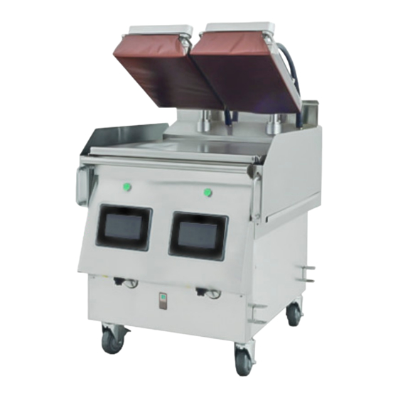
Electric/Gas Dual Side Grill
Installation, Operation and Maintenance Manual
Please read all sections of this manual and retain for future reference.
Models:
ME-1P, ME-2P, ME-3PX
MG-1P, MG-2P, MG-3PX
M(E/G)-2P
Original Document
Document #: GAR_IOM_4600921_Rev 10 – 05/23
Bring Your Passion to the Surface
Post in a prominent location, instructions to be followed
in the event the user smell gas. This information shall be
obtained by consulting your local gas supplier.
Do not store or use gasoline or other flammable vapors
and liquids in the vicinity of this or any other appliance.
Improper installation, adjustment, alteration, service
or maintenance can cause property damage, injury, or
death. Read the installation, operating and maintenance
instructions thoroughly before installing or servicing
this equipment.
M(E/G)-3PX
Read this instruction before operating this equipment.
Warning
n
FOR YOUR SAFETY
Warning
n
Caution
,
C
US
Advertisement
Table of Contents


Need help?
Do you have a question about the ME-1P and is the answer not in the manual?
Questions and answers