Table of Contents
Advertisement
Quick Links
SERVICE MANUAL
JACK IN THE BOX
GAS XPRESS GRILLS,
MODELS XG24-JIB, XG36-JIB
FOR YOUR SAFETY:
DO NOT STORE OR USE GASOLINE
OR OTHER FLAMMABLE VAPORS OR
LIQUIDS IN THE VICINITY OF THIS OR ANY OTHER
APPLIANCE
WARNING:
IMPROPER INSTALLATION, ADJUSTMENT,
ALTERATION, SERVICE OR MAINTENANCE CAN
CAUSE PROPERTY DAMAGE, INJURY, OR DEATH.
READ THE INSTALLATION,
OPERATING AND MAINTENANCE
INSTRUCTIONS THOROUGHLY
BEFORE INSTALLING OR
SERVICING THIS EQUIPMENT
NOTE:
THIS MANUAL PERTAINS TO ALL XPRESS GRILL
MODELS LISTED ABOVE. THE READER/OPERATOR
MUST INTERPRET ITS CONTENTS TO APPLICABLE
NEEDS. HOWEVER, IF THERE IS ANY QUESTION OF
INTERPRETATION OF ANY LITERATURE PERTAINING
TO GARLAND GRILLS, PLEASE CONTACT OUR
CUSTOMER SERVICE DEPARTMENT AT ONE OF THE
PHONE NUMBERS LISTED BELOW.
GARLAND COMMERCIAL INDUSTRIES, LLC
185 East South Street
Freeland, Pennsylvania 18224
Phone: (570) 636-1000
Fax: (570) 636-3903
Part #JIBSM08 Rev 7 (08/04/09)
Part # JIBSM08 Rev.6 (08/04/09)
MODEL NUMBERS:
XG24-JIB,XG36-JIB
PLEASE READ ALL SECTIONS OF THIS MANUAL AND
RETAIN FOR FUTURE REFERENCE.
THIS PRODUCT HAS BEEN CERTIFIED AS COMMERCIAL
COOKING EQUIPMENT AND MUST BE INSTALLED BY
PROFESSIONAL PERSONNEL AS SPECIFIED.
CAUTION: THIS EQUIPMENT MUST ONLY BE OPERATED
UNDER AN APPROVED HOOD SYSTEM
IN THE COMMONWEALTH OF MASSACHUSETTS
THIS PRODUCT MUST BE INSTALLED BY A LICENSED
PLUMBER OR GAS FITTER.
For Your Safety:
Post in a prominent location, instructions to be
followed in the event the user smells gas. This
information shall be obtained by consulting your local
gas supplier.
GARLAND COMMERCIAL RANGES, LTD.
1177 Kamato Road, Mississauga, Ontario L4W 1X4
CANADA
Phone: 905-624-0260
Fax: 905-624-5669
© 2008 Garland Commercial Industries, LLC
Page 1
Advertisement
Table of Contents
Troubleshooting

Related Manuals for Garland XG24-JIB


Summary of Contents for Garland XG24-JIB
-
Page 1: For Your Safety
NEEDS. HOWEVER, IF THERE IS ANY QUESTION OF INTERPRETATION OF ANY LITERATURE PERTAINING information shall be obtained by consulting your local TO GARLAND GRILLS, PLEASE CONTACT OUR gas supplier. CUSTOMER SERVICE DEPARTMENT AT ONE OF THE PHONE NUMBERS LISTED BELOW. -
Page 2: Table Of Contents
To View Recovery Time - Grill: ......27 To View the Garland Part Number: ..... 27 GRILL CONTROLS . - Page 3 Probe Locations: ........34 XG24-JIB XPRESS GRILL GAS TROUBLESHOOTING .
-
Page 4: Xg24-Jib Model
19.4 (1207mm) (813mm) (152mm) (76mm) Shipping: Weight 575Lbs/ 234Kg, 45 Cubic Feet TOP HEATER Garland products are not approved or authorized for home or 11 1/2" TOP VIEW residential use, but are intended for commercial applications 1 3/4" [292mm] [44mm] only. -
Page 5: Xg36-Jib Model
29.1 (1207mm) (1035mm) (152mm) (76mm) Shipping: Weight 965Lbs/ 438Kg, 59 Cubic Feet TOP HEATER Garland products are not approved or authorized for 11 1/2" 1 3/4" home or residential use, but are intended for commercial TOP VIEW [292mm] [44mm] applications only. Garland will not provide service,... -
Page 6: Plug Configuration
Maximum Minimum (includes electrical Voltage Plug Type Gauge NEMA Plug Model Current Cord and gas inlet (3ph Delta) Supplied (Amps) Gauge plumbing) XG24-JIB 24.90 4-10AWG 37.43 4-6AWG 4524785 4-6AWG 15-50P XG36-JIB 32.43 4-8AWG X GND 4525509 4-10AWG 15-30P XG24-JIB 21.61... -
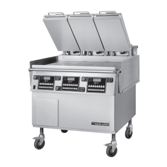
Page 7: Introduction
INTRODUCTION The Garland Xpress grill, for Jack in the Box provides than overland, and overtime costs of repair. We exclude a method for efficient two-sided cooking, while broken glass, paint and porcelain finish, surface rust, gasket accommodating a variety of products. The unit will also serve material, ceramic material, light bulbs and fuses from normal as a flat grill, and meets all of Jack in the Box’s standards for... - Page 8 SAFETY continued When two sided cooking, the area between the upper platen WARNING: After turning the master power switch to the and the griddle plate should be regarded as a “danger zone. ” START position, the grill will go through initialization. If During two sided cooking the operator must not be within the upper platens are in the lowered position they will this danger zone.
-
Page 9: Unit Installation
UNIT INSTALLATION Rating Plate Location Installation shall be made with the gas connector that has been specified by The Jack in the Box Corporation and is IMPORTANT: Rating plates for this appliance are located in supplied loose with the grill. The quick disconnect fitting and two places: 1) inside back panel on left side, 2) under front gas shut off valve must be installed in the direction indicated control panel on center . -
Page 10: Appliances Equipped With Casters
UNIT INSTALLATION continued Electrical Connections: The grill must be disconnected from the gas supply system when pressure testing of that system at pressures in excess of All electrically operated appliances must be electrically 1/2 psi (3.45kPa). grounded in accordance with local codes; or in the absence Check the data plate to determine the proper type of gas of local codes, with the latest edition of National Wiring before connecting the quick disconnect or piping from the... -
Page 11: Accessory Kit - Electrical Supply Lines
UNIT INSTALLATION continued B. Install the nipple assembly into the elbow (3/4” NPT) Installation of Cord And Plug With Strain Relief: Refer to Photo A 1. Remove the left grease bucket support attached by two C. Install the manifold support bracket over the nipple metal screws and the stainless steel left side body panel attaching it to the circular bracket on the nipple. -
Page 12: Electrical Connection Terminal Block Connection
UNIT INSTALLATION continued 4. Insert loose wires and strain relief cord end through Note: see diagram below for connections to terminal block. the hole at the bottom of the unit. Refer to photo F and secure with locknut. Refer to photo E. Wire leads from Main Terminal Cord and Plug... -
Page 13: Burner Air Adjustment
UNIT INSTALLATION continued The gas valve, enrichment tube igniter and orifice must be 1. Loosen the two 5\16” hex head #10 screws just outboard changed to that supplied by the Authorized Service Agency of the igniter. This allows the igniter and its bracket for the gas you are changing to. -
Page 14: Grill Controls
GRILL CONTROLS WHEN PUSHED SIMULTANEOUSLY: "START COOK TIME COUNTDOWN" (flat grill cooking) OR "LOWER PLATEN" (two-sided cooking) DISPLAY INDICATORS CANCEL/ RAISE PLATEN BUTTON PRODUCT BUTTONS POWER ENTER MASTER BUTTON BUTTON POWER PROGRAM DOWN ARROW SWITCH BUTTON BUTTON TEMPERATURE UP ARROW BUTTON BUTTON Master Power Switch:... -
Page 15: Program Button
GRILL CONTROLS continued Program Button: Enter Button: The primary function is to access Programming and Function is to accept programming steps. Calibration of the grill. Push and hold for five (5) seconds. Cancel/Raise Platen Button, (Green): Display will ask for the code. After entering code, five programming features will be accessible “MENU ITEMS, ”... -
Page 16: Platen Zeroing
PLATEN ZEROING Turn Master power switch “ON”, wait for controllers to display 10. Move next to the left front adjuster and raise the platen “OFF”. until the gapping tool fits snugly between the upper platen and grill surface. Note: Release sheets should not be installed during this procedure. - Page 17 PLATEN ZEROING continued Platen Gapping Tool (PN 1838701) “No-Go” “Go” Platen leveling should be done from one corner to the opposite corner. The adjuster nuts should be turned opposite of one another. Platen Adjusting Tool (PN 4523323) This end to remove Adjuster Locking Cap This end to remove Grease Cap and to make adjustments to the...
-
Page 18: Optional Accessories
OPTIONAL ACCESSORIES Teflon Sheet - 1799302 Teflon Clip - 1851303 Grill Squeegee - 1868201 Teflon Tool - 4525560 Page 18 Part # JIBSM08 Rev 7 (08/04/09) -
Page 19: Release Material Installation
The following procedures are the procedures for installing Holding the bottom of the release material sheet in place, the Teflon sheets on to the upper platen on the Garland gently pull the sheet toward the front of the platen. Xpress grill. The components shown below are included with Thread the front edge of the release material sheet behind your grill when purchased. -
Page 20: Normal Operation
NORMAL OPERATION Installing Release Material: 2. The controller regulates the platen and grill temperatures to the set temperatures of the product selected and For installation instructions, see section on RELEASE reads “TOO COOL” or “TOO HOT” with “MENU ITEM”, until MATERIAL INSTALLATION. -
Page 21: Enter Standby Mode
NORMAL OPERATION continued To Display the Current Temperatures: 4 To cancel a cook cycle at anytime the press the green CANCEL/RAISE PLATEN BUTTON . 1. Press the button and repeat for each zone to be 5. During a cook cycle, the display shows the product recipe displayed... -
Page 22: Extended Time
NORMAL OPERATION continued EXTENDED TIME: START DELAY: This option will add 6, 4 and 2 seconds to the time of the next This number is how long the operator must hold the GREEN three cooks respectively if the grill has had no activity for (‘CANCEL/RAISE’) and BLACK buttons to start a cooking cycle 5 minutes. - Page 23 CLEANING AND MAINTENANCE continued 9. Open one packet of high-temperature grill cleaner, Caution: Ice, cold water, or large quantities of water must never be applied to the grill plate or upper platen . Severe (several cleaners may be available on the market), and empty the contents into a suitable container.
-
Page 24: Programming
PROGRAMMING Programming Modes/Menu Sequence: System Information System Information Page 24 Part # JIBSM08 Rev 7 (08/04/09) - Page 25 PROGRAMMING continued System Set-up System Set-up Service Mode Service Mode Part # JIBSM08 Rev.6 (08/04/09) Page 25...
-
Page 26: Menu Items
PROGRAMMING continued Menu Items... 5. Use to choose the desired Menu Item. To Change the Cook Time of a Product: 6 Press three, (3) times to display “(MENU ITEM) UPPER TEMP XXX” displayed in °F or °C. 1. Press and hold for three, (3) seconds. -
Page 27: To Change Product Button, "Key" Assignment
SYSTEM INFO. ” 9. Press to exit. 5. Press three, (3), times to view the Garland Part Number System Info... for the grill. “GARLAND PART # X…X” is displayed. (number varies by grill). To View Recovery Time - Upper Platen: 6. -
Page 28: To View The Flash Number
PROGRAMMING continued To View the Flash Number: 5. Press six, (6), times to view the Download Number. “DOWNLOAD NUMBER X…X” is displayed. (Download 1. Press and hold for three, (3) seconds. “ENTER CODE” is number varies by grill). displayed. 6. Press to return to “PROGRAMMING MODE SYSTEM 2. -
Page 29: To Change The Alarm Volume
PROGRAMMING continued To Change Probe Calibration - Upper: 8. Press to return to “PROGRAMMING MODE SYSTEM SETUP” 1. Press and hold for three, (3) seconds. “ENTER CODE” is displayed. 9. Press again to exit. To Change the Alarm Volume: 2. Using the Product buttons, 0-9 enter the code, (1251). “ENTER CODE **** ”... -
Page 30: To Change Platen Set
PROGRAMMING continued • Temperature is currently falling from a detected peak 9. Press again to exit. of 360°F or higher . To Change Control Type: • Temperature is falling and has fallen 2°F from a detected peak that is within the 350-360°F range . (i .e . Note: this must be verified if the control is changed, match calibration would be allowed at 355°F if the achieved the new control to the grill. -
Page 31: To Change The Grill Function
PROGRAMMING continued To Change the Grill Function: To Change the Alarm Mode: 1. Press and hold for three, (3) seconds. “ENTER CODE” is 1. Press and hold for three, (3) seconds. “ENTER CODE” is displayed. displayed. 2. Using the Product buttons, 0-9 enter the code, (1251). 2. -
Page 32: To Modify A Product Name In Library
PROGRAMMING continued Service Mode 3. Press to enter the Programming Mode. “PROGRAMMING MODE MENU ITEMS” is displayed. To Change SCK Address: 4. Press three, (3) times. “PROGRAMMING MODE PROD 1. Press and hold for three, (3) seconds. “ENTER CODE” is NAME LIB”... -
Page 33: Calibration
CALIBRATION Bi-Weekly Calibration: 3. Press and hold for three, (3) seconds. “ENTER CODE” is displayed. Tools: Digital Pyrometer with Surface Probe 4. Using the Product buttons, 0-9 enter the code, (1251). Warning: PERSONAL INJURY FROM BURNS MAY RESULT “ENTER CODE **** ” is displayed. WHEN COMING IN CONTACT WITH HOT COOKING SURFACES . -
Page 34: Probe Locations
5.75" 5.75" 5.75" 22.5" 22.5" 11.25" 11.25" PLATEN PLATEN (2 PLACES) (3 PLACES) GRILL PLATE GRILL PLATE 24" 24" 12" 12" 6.09" 6.09" 6.09" 6.09" 18" 24" 36" MODEL XG24-JIB MODEL XG36-JIB Page 34 Part # JIBSM08 Rev 7 (08/04/09) -
Page 35: Troubleshooting
MAINTENANCE AND REPAIRS SHOULD BE PERFORMED BY Press to reset the message and silence the beep. YOUR LOCAL GARLAND AUTHORIZED SERVICE AGENCY . MOTOR OVER CURRENT: PROBE ERROR: ...displayed when the platen has been mechanically resisted. -
Page 36: Technical Troubleshooting
TECHNICAL TROUBLESHOOTING Master Power (ON / OFF) Switch turned ON - Power light or indicator is not lit Reconnect power supply, Control power cord(s) unplugged Check Ansul reset Circuit breaker at Line voltage not present service panel is “OFF” or tripped Reset circuit breaker Check for Line voltage at terminal... -
Page 37: Controller Displays "Too Hot
TECHNICAL TROUBLESHOOTING continued Controller Displays “Too Hot” Current product selected requires Allow grill to cool down a lower operating temperature to current set temperature that the previous one selected. of selected product Zone is continuously heating, Replace Solid State Relay and temperature is rising. -
Page 38: Controller Displays "Faulty Element Or Shorted Probe" -Only 1 Or 2 Zones Led Lights Are Red
TECHNICAL TROUBLESHOOTING continued Controller Displays “FAULTY ELEMENT OR SHORTED PROBE” - Only 1 or 2 zones LED lights are RED Replace Bad Contactor Check for 3-phase Check for 3-phase voltage at primary voltage at secondary side of main contactors side contactor Check for disconnected or YE S damaged molex plugs... -
Page 39: Controller Displays "Probe Error
TECHNICAL TROUBLESHOOTING continued Controller displays “PROBE ERROR” Disconnect suspected Controller displays “Probe thermocouple and check ERROR” when grill is turned Replace damaged thermocouple continuity. Check all connections on Has suspected Controller displays “Probe Re-establish thermoscouple interface zone overheated? ERROR” during normal operation. positive connection board. -
Page 40: Controller Displays "Heating Error Or Probe Errorplaten And Grill Led's Are Red (Both Sides)
TECHNICAL TROUBLESHOOTING continued Controller Displays “HEATING ERROR or PROBE ERROR PLATEN and GRILL LED’s are RED (Both Sides) See Technical Troubleshooting “Controller display is BLANK, Main Power (ON/OFF) Light IS LIT” Check for 3-phase voltage Check for 3-phase voltage at at secondary side of contactor primary side of main contactors Check for disconnected... -
Page 41: Controller Display Is Blank, Main Power (On / Off) Light Or Indicator Is Lit
TECHNICAL TROUBLESHOOTING continued Controller Display is BLANK, Main Power (ON / OFF) light or indicator is LIT Check for loose or disconnected black wires on Check for 120 VAC at terminal coil of contactor and black marked “LIM” & “N” wires going to 24VAC transformers. -
Page 42: Master Power (On / Off) Switch Turned On - Power Light In On - Grill Is Not Heating
TECHNICAL TROUBLESHOOTING continued Master Power (ON / OFF) Switch turned ON - Power Light in On - Grill is not heating Controller display Press the MENU SELECT YE S reads “OFF” button. High voltage power YE S Reconnect power supply cord(s) unplugged High voltage circuit breaker at service panel is OFF or tripped... -
Page 43: Controller Displays "Motor Over Current" - Platen Does Not Move At All
TECHNICAL TROUBLESHOOTING continued Controller Displays “MOTOR OVER CURRENT” - Platen does not move at all Check voltage of limit switches. 5.6 VDC when Replace defective Limit Switch switch is Open, 0 VDC when switches are closed. Check for 120 - 140 VDC on Replace defective Motor Check for 120 volts at the pins 1 &... -
Page 44: Controller Displays "Ignition Failure
TECHNICAL TROUBLESHOOTING continued Controller Displays “IGNITION FAILURE” - No flame at all Check for proper gas Do the burners light at all? Does the ame go out? pressure - Incoming & manifold pressure Check quick disconnect Reconnect quick disconnect Adjust incoming & burner for improper connection on gas supply hose pressure for gas type... -
Page 45: Controller Displays "Ignition Failure" - Module Is Sparking, Flame Comes On And Goes Out
TECHNICAL TROUBLESHOOTING continued Controller Displays “IGNITION FAILURE” - Module is sparking, flame comes on and goes out Check wiring connections Dig Gas Valve Open? Check for 120VAC output from between Ignition Module, Check for 120 VAC across gas ignition module, terminal and Gas Valve. -
Page 46: Linear Actuator Replacement
LINEAR ACTUATOR REPLACEMENT 1. Disconnect the cable 6. Push the pin through from the Motor Speed the actuator base Control. toward the inside of the grill. Reach around to the inside and remove. 2. Disconnect the motor 7. Remove the Linear leads from the wire Actuator from the grill, harness. - Page 47 LINEAR ACTUATOR REPLACEMENT continued 11. Gently fit clevis clip through top of actuator shaft and cross member bar. Use pry bar to align holes. 12. Reconnect wires as shown in the photos to the right. Part # JIBSM08 Rev.6 (08/04/09) Page 47...
- Page 48 Page 48 Part # JIBSM08 Rev 7 (08/04/09)
-
Page 49: Parts List
PARTS LIST MASTER SERIES XG24-JIB XPRESS GRILL GAS Contents XPRESS - GRILL COMPLETE VIEW . . . . . . . . . . . . . . . . . . . . . . . . . . . . . . . . . . . . . . . . . . . . . . . . 50 XPRESS GRILL ACTUATOR . -
Page 50: Xpress - Grill Complete View
XPRESS - GRILL COMPLETE VIEW MODEL XG24-JIB XG24-JIB#1 Page 50 Part # JIBSM08 Rev 7 (08/04/09) - Page 51 GARLAND PARTS IDENTIFICATION Gas - Xpress Grill Complete Exploded View - Model: XG24-JIB ITEM PART # DESCRIPTION QUANTITY 4516708 Body Base Wa 4516718 Plate Wa Page 52 Actuator Assembly Page 54 Platen Assembly Page 56 Burner Assembly Page 58 Component Bracket Assembly...
-
Page 52: Xpress Grill Actuator
XPRESS GRILL ACTUATOR ASSEMBLY VIEW MODEL XG24-JIB XG24-JIB#2 Page 52 Part # JIBSM08 Rev 7 (08/04/09) - Page 53 GARLAND PARTS IDENTIFICATION Gas - Xpress Grill Actuator Assembly View - Model: XG24-JIB ITEM PART # DESCRIPTION QUANTITY 4516080 Actuator Frame Wa 4516096 Pillow Block 1812401 Actuator 1857601 Switch Bracket 1855601 Upper/Lower Platen Limit Switch 1858001 Actuator Mount Block 4516097...
-
Page 54: Xpress Grill Platen
XPRESS GRILL PLATEN ASSEMBLY VIEW MODEL XG24-JIB Available Separately if needed Available as a complete assembly only Available Separately if needed XG24-JIB#3 Page 54 Part # JIBSM08 Rev 7 (08/04/09) - Page 55 GARLAND PARTS IDENTIFICATION Gas - Xpress Grill Platen Assembly View - Model: XG24-JIB ITEM PART # DESCRIPTION QUANTITY 4516085 Platen Arm 4516087 Carriage Block, Rt 4516088 Carriage Block, Lt 1858501 Pivot Stop Knob 1858502 Pivot Stop Pin 4516092 Platen Lid...
-
Page 56: Xpress Grill Burner
XPRESS GRILL BURNER ASSEMBLY VIEW MODEL XG24-JIB XG24-JIB#4 Page 56 Part # JIBSM08 Rev 7 (08/04/09) - Page 57 GARLAND PARTS IDENTIFICATION Gas - Xpress Grill Burner Assembly View - Model: XG24-JIB ITEM PART # DESCRIPTION QUANTITY 4517403 Burner Assembly, Lp 4517462 Burner Assembly, Nat 4517396 Flue Box, Inner 4517397 Flue Box, Outer 4517398 Flue Bottom 4517399 Flue Top...
-
Page 58: Xpress Grill Component Bracket
XPRESS GRILL COMPONENT BRACKET ASSEMBLY VIEW MODEL XG24-JIB XG24-JIB#5 Page 58 Part # JIBSM08 Rev 7 (08/04/09) - Page 59 GARLAND PARTS IDENTIFICATION Gas - Xpress Grill Component Bracket Assembly View - Model: XG24-JIB ITEM PART # DESCRIPTION QUANTITY 4516682 Component Bracket 4516989 Motor Speed Control 4516079 Contactor Bracket 1269800 24 Volt Transformer 1637001 Contactor 1864901 Ignition Module * NOT ILLUSTRATED RECOMMENDED STOCK PARTS Part # JIBSM08 Rev.6 (08/04/09)
-
Page 60: Xpress Grill Heat Sink
XPRESS GRILL HEAT SINK ASSEMBLY VIEW MODEL XG24-JIB XG24-JIB#6 Page 60 Part # JIBSM08 Rev 7 (08/04/09) - Page 61 GARLAND PARTS IDENTIFICATION Gas - Xpress Grill Heat Sink Assembly View - Model: XG24-JIB ITEM PART # DESCRIPTION QUANTITY 4516116 Heat Sink 4516988 Relay 4517392 Pressure Switch * NOT ILLUSTRATED RECOMMENDED STOCK PARTS Part # JIBSM08 Rev.6 (08/04/09) Page 61...
-
Page 62: Revision History
REVISION HISTORY GARLAND PARTS IDENTIFICATION Revision History REV. # PAGE # ITEM # NOTE DATE Part List Book Released Jul 16/08 Page 62 Part # JIBSM08 Rev 7 (08/04/09) -
Page 63: Xg36-Jib Xpress Grill Gas
PARTS LIST continued PARTS LIST MASTER SERIES XG36-JIB XPRESS GRILL GAS Contents GRILL COMPLETE ASSEMBLY . . . . . . . . . . . . . . . . . . . . . . . . . . . . . . . . . . . . . . . . . . . . . . . . . . . 64 ACTUATOR ASSEMBLY . -
Page 64: Grill Complete Assembly
GRILL COMPLETE ASSEMBLY ASSEMBLY VIEW MODEL XG36-JIB XG36 - JIB#1 Page 64 Part # JIBSM08 Rev 7 (08/04/09) - Page 65 GARLAND PARTS IDENTIFICATION Gas - Xpress Grill Complete Exploded View - Model: XG36-JIB ITEM PART # DESCRIPTION QUANTITY CRITICAL 4516058 Body Base Weld Assembly 4517657 Plate Weld Assembly Page 68 Actuator Assembly Page 70 Platen Assembly Page 72 Burner Assembly...
- Page 66 GARLAND PARTS IDENTIFICATION Gas - Xpress Grill Complete Exploded View - Model: XG36-JIB ITEM PART # DESCRIPTION QUANTITY CRITICAL Page 72 Flue Assembly 1 per zone 1869301 Transformer Bracket 4516114 Circuit Brace 4520578 Grill Plate Thermocouple 1 per zone 1866103 Strain Relief Wire 12.5”...
- Page 67 Part # JIBSM08 Rev.6 (08/04/09) Page 67...
-
Page 68: Actuator Assembly
ACTUATOR ASSEMBLY ASSEMBLY VIEW MODEL XG36-JIB XG36-JIB#2 Page 68 Part # JIBSM08 Rev 7 (08/04/09) - Page 69 GARLAND PARTS IDENTIFICATION GAS - XPRESS GRILL ACTUATOR ASSEMBLY VIEW - MODEL: XG36-JIB ITEM PART # DESCRIPTION QUANTITY CRITICAL 4516080 Actuator Frame Wa 4518156 Pillow Block Assembly 4525541 Linear Actuator 1857601 Switch Bracket 1855601 Upper/Lower Platen Limit Switch 4518787 Actuator Mount Block (Painted)
-
Page 70: Platen Assembly
PLATEN ASSEMBLY ASSEMBLY VIEW MODEL XG36-JIB Available Separately if needed Available Separately if needed Available as a complete assembly only Available Separately if needed Available Separately if needed Available Separately if needed XG36 - JIB#3 Page 70 Part # JIBSM08 Rev 7 (08/04/09) - Page 71 GARLAND PARTS IDENTIFICATION Gas - Xpress Grill Platen Assembly View - Model: XG36-JIB ITEM PART # DESCRIPTION QUANTITY CRITICAL 4516085 Platen Arm 4520422 Carriage Block, Assembly, Rt 4520423 Carriage Block, Assembly, Lt 4522581 1/16 TH Silicone Gasket 3.5 Ft 4516092...
-
Page 72: Xpress Grill Burner
XPRESS GRILL BURNER ASSEMBLY VIEW MODEL XG35-JIB XG36-JIB#4 Page 72 Part # JIBSM08 Rev 7 (08/04/09) - Page 73 GARLAND PARTS IDENTIFICATION Gas - Xpress Grill Burner Assembly View - Model: XG36-JIB ITEM PART # DESCRIPTION QUANTITY UP TO FROM CRITICAL 4517403 Burner Assembly, Lp 4517462 Burner Assembly, Nat 4517396 Flue Box, Inner 4517397 Flue Box, Outer 4517398 Flue Bottom...
-
Page 74: Xpress Grill Bracket
XPRESS GRILL BRACKET ASSEMBLY VIEW MODEL XG36JIB XG36 - JIB#5 Page 74 Part # JIBSM08 Rev 7 (08/04/09) - Page 75 GARLAND PARTS IDENTIFICATION Gas - Xpress Grill Component Bracket Assembly View - Model: XG36-JIB ITEM PART # DESCRIPTION QUANTITY CRITICAL 4516078 Component Mounting Bracket 4516989 Motor Speed Control 4516079 Contactor Bracket 1269800 24 Volt Transformer 1637001 Contactor 1864901 Ignition Module...
-
Page 76: Xpress Grill Heat Sink
XPRESS GRILL HEAT SINK ASSEMBLY VIEW MODEL XG36-JIB XG36-JIB#6 Page 76 Part # JIBSM08 Rev 7 (08/04/09) - Page 77 GARLAND PARTS IDENTIFICATION Gas - Xpress Grill Heat Sink Assembly View - Model: XG36-JIB ITEM PART # DESCRIPTION QUANTITY CRITICAL 4516116 Heat Sink 1 Per Zone 4516988 Relay 4517392 Pressure Switch 1811903 Thermal Interface MAT * NOT ILLUSTRATED RECOMMENDED STOCK PARTS Part # JIBSM08 Rev.6 (08/04/09)
-
Page 78: Wiring Harness And Description Where Used
WIRING HARNESS AND DESCRIPTION WHERE USED GARLAND PARTS IDENTIFICATION Gas - Xpress Grill Wire Harness And Description Where Used - Model: XG36-JIB ITEM PART # DESCRIPTION & LOCATION QUANTITY CRITICAL Description: 120V Harness 1859850 Location: Motor Speed Control, 120 volt side of 120/24 volts transformer, Power to Actuator, 120 volts terminal block. -
Page 79: Accessories And Tools
ACCESSORIES AND TOOLS GARLAND PARTS IDENTIFICATION Gas - Xpress Grill Accessories And Tools - Model: XG36-JIB ITEM PART # DESCRIPTION QUANTITY CRITICAL 4523323 Platen Adjuster Tool 4525560 Teflon Tool 1838701 Platen Leveling Tool CK 1868201 Grill Wiper 4526114 Tool Holder for Scraper... -
Page 80: Gas Tubing
GAS TUBING, Gas - Xpress Grill Gas Tubing - Model: XG36-JIB ITEM PART # DESCRIPTION QUANTITY CRITICAL 4517378 Tubing, Left - (Location, left zone) 4517377 Tubing, Center - (Location, center zone) 4517376 Tubing, Right - (Location, right zone) * NOT ILLUSTRATED RECOMMENDED STOCK PARTS CENTER ZONE RIGHT ZONE... -
Page 81: Revision History
REVISION HISTORY GARLAND PARTS IDENTIFICATION Revision History REV. # PAGE # ITEM # NOTE DATE Parts List Book Released Oct 27/08 New Drawing 3,4,5 Quantity Changed – Was 2 All Three Quantity Changed – Was 1 Per Zone Part # Changed 26B Was 1856801, 26C Was 1354902,... -
Page 82: Wiring Diagram
WIRING DIAGRAM ACTUATOR 1333W MOTOR YELLOW GRIDDLE GRIDDLE YELL PLATEN PLATEN 120V 240V SWITCH MAIN Page 82... - Page 83 WIRING DIAGRAM ACTUATOR 1333W MOTOR YELLOW GRIDDLE GRIDDLE YELL PLATEN PLATEN 120V 240V SWITCH MAIN Page 83...
-
Page 84: Controller Menu Items
CONTROLLER MENU ITEMS The following table list menu items defaulted in the main controller. To reprogram any function or feature below, see programming section. Jack in the Box Menu Items Step Process Menu Items Platen Screen Display Menu Cook Yes/ Bottom Assign Button... -
Page 85: Temperature Conversion (F / C)
TEMPERATURE CONVERSION (F / C) Part # JIBSM08 Rev.6 (08/04/09) Page 85... - Page 86 Page 86 Part # JIBSM08 Rev 7 (08/04/09)
- Page 87 Part # JIBSM08 Rev.6 (08/04/09) Page 87...
Need help?
Do you have a question about the XG24-JIB and is the answer not in the manual?
Questions and answers