Cisco IE 4010 Hardware Installation Manual
Hide thumbs
Also See for IE 4010:
- Hardware installation manual (76 pages) ,
- Software configuration manual (1066 pages) ,
- Product documentation (28 pages)
Table of Contents
Advertisement
Advertisement
Table of Contents

Related Manuals for Cisco IE 4010


Summary of Contents for Cisco IE 4010
- Page 1 Cisco IE 4010 Switch Hardware Installation Guide First Published: 2016-09-01 Last Modified: 2023-07-28 Americas Headquarters Cisco Systems, Inc. 170 West Tasman Drive San Jose, CA 95134-1706 http://www.cisco.com Tel: 408 526-4000 800 553-NETS (6387) Fax: 408 527-0883...
- Page 2 © 2016–2023 Cisco Systems, Inc. All rights reserved.
-
Page 3: Table Of Contents
Alarm LEDs SD Flash Memory Card LED USB LED System LED Power-Supply Side Power-Supply Side LEDs Power Supply Features Management Options Network Configurations C H A P T E R 2 Switch Installation Cisco IE 4010 Switch Hardware Installation Guide... - Page 4 Installing a Power-Supply Module Equipment That You Need Grounding the Switch Installing the Power-Supply Module in the Switch Installing the DC Power Supply in the Switch Wiring the Power Source Removing the Power-Supply Module Cisco IE 4010 Switch Hardware Installation Guide...
- Page 5 EMC Environmental Conditions for Products Installed in the European Union Hazardous Locations Standards C H A P T E R 6 Cable and Connectors Connector Specifications 10/100/1000 Ports SFP Module Connectors Console Port Alarm Port Cisco IE 4010 Switch Hardware Installation Guide...
- Page 6 RJ-45 Console Port USB Console Port Installing the Cisco Microsoft Windows XP, 2000, Vista, 7, 8, and 10 USB Device Driver Uninstalling the Cisco Microsoft Windows XP, 2000, Vista, 7, 8, and 10 USB Driver Entering the Initial Configuration Information...
-
Page 7: Product Overview
C H A P T E R Product Overview The Cisco IE 4010 switch provides a rugged and secure switching infrastructure for harsh environments. It is suitable for industrial Ethernet applications, including process manufacturing, utility substations, intelligent transportation systems (ITSs), rail transportation, and other similar deployments. -
Page 8: Cable Side
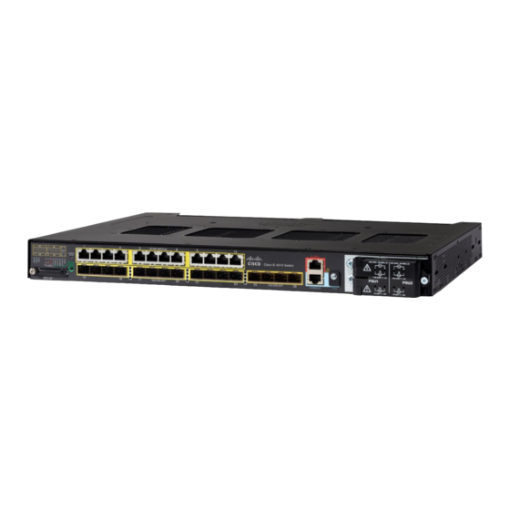
L-IE4000-RTU= (Electronic SW License for IE4000 Switches) Cable Side Figure 1: Cisco IE-4010-16S12P Cable-Side View Table 2: LEDs Express Setup button Twelve 10/100/1000 PoE/PoE+ Ports (Downlinks) Alarm port USB (mini-Type B) console port Power-input terminal Cisco IE 4010 Switch Hardware Installation Guide... -
Page 9: 10/100/1000 Poe/Poe+ Ports (Downlinks)
Statement 1072 The 10/100/1000 PoE ports on the Cisco IE-4010 switches provide PoE support for devices that are compliant with IEEE 802.3af/802.3at. The Cisco prestandard PoE is also supported for Cisco IP Phones and Cisco Aironet Access Points. -
Page 10: Alarms
The cover is hinged and closed with a captive screw. This prevents the card from coming loose and protects against shock and vibration. For more information on inserting and removing the flash memory card, see Power-Supply Side, on page Cisco IE 4010 Switch Hardware Installation Guide... -
Page 11: Display Mode Button
The switch Ethernet SFP modules provide connections to other devices. These field-replaceable transceiver modules provide the interfaces. The IE 4010 supports both FE and GE optics. SFP modules have local connectors (LCs) for fiber-optic connections or RJ-45 connectors for copper connections. -
Page 12: Switch Panel Leds
Product Overview Switch Panel LEDs To use the USB console port, you must install the Cisco Windows USB device driver on the device that is connected to the USB console port (device running with Microsoft Windows). See Installing the Cisco Microsoft Windows XP, 2000, Vista, 7, 8, and 10 USB Device Driver, on page 72 for more information. -
Page 13: Port Leds
ON solid green when a mode is selected and turn OFF when timeout (5 seconds) or a different mode is selected. When you change port modes, the meanings of the port LED colors also change. The following table explains how to interpret the port LED colors in different port modes. Cisco IE 4010 Switch Hardware Installation Guide... - Page 14 Port is operating at 1000 Mb/s. Uplinks Ports Port is operating at 1000 Mb/s. Green Port is not operating. DUPLX (duplex) Amber Port is operating in half duplex. Green Port is operating in full duplex. Cisco IE 4010 Switch Hardware Installation Guide...
-
Page 15: Display Mode Button
The Display Mode Button allows you to choose the mode you want displayed by the port LEDs. The LEDs with green text to the left of the Button indicate the chosen display mode. Each time you press the switch, the mode indicator moves from SPEED, DUPLX, REDUN, SYNCE, and PoE respectively. Cisco IE 4010 Switch Hardware Installation Guide... -
Page 16: Power-Supply Module Leds
Unsupported SD flash memory card is detected. Slow blinking amber SD flash memory card is not present. Green SD flash memory card is functioning. Blinking green SD flash memory card transfer in progress. Cisco IE 4010 Switch Hardware Installation Guide... -
Page 17: Usb Led
System is receiving power but is not functioning properly Power-Supply Side The power-supply side has the LED panel and two power-supply slots for the removable power supplies. Figure 5: Switch with Both Power-Supply Modules Cisco IE 4010 Switch Hardware Installation Guide... -
Page 18: Power-Supply Side Leds
Mini-USB console port status SD flash memory card status Alarms 1-4 and OUT Alarm ports and Alarm Output status PSU 1-2 Power supply 1and 2 status SPEED Port speed status DUPLX Port duplex status Cisco IE 4010 Switch Hardware Installation Guide... -
Page 19: Power Supply Features
• You can manage switches from a Simple Network Management Protocol (SNMP)-compatible management station. The switch supports a comprehensive set of Management Information Base (MIB) extensions and four Remote Monitoring (RMON) groups. See the switch software configuration guide on Cisco.com and the documentation that came with your SNMP application for information. -
Page 20: Network Configurations
Prime Infrastructure • Cisco Prime Infrastructure simplifies the management of wireless and wired networks. It offers Day 0 and 1 provisioning, as well as Day N assurance from the branch to the data center. We call it One Management. -
Page 21: Switch Installation
Installing the Switch, on page 17 Warnings These warnings are translated into several languages in the Regulatory Compliance and Safety Information for the Cisco IE 4010 Switch document. These warning statements apply to all the switches: Warning Before working on equipment that is connected to power lines, remove jewelry (including rings, necklaces, and watches). - Page 22 To prevent airflow restriction, allow clearance around the ventilation openings to be at least: 1.75 in. (4.4 cm). Statement 1076 Warning Avoid using or servicing any equipment that has outdoor connections during an electrical storm. There may be a risk of electric shock from lightning. Statement 1088 Cisco IE 4010 Switch Hardware Installation Guide...
-
Page 23: Installation Guidelines
POST, the SYS LED turns green. The other LEDs turn off and return to their operating status. If the switch fails POST, the SYS LED is amber Note Contact Cisco Systems immediately if your switch fails POST. After a successful POST, disconnect the power from the switch. For more information, see Wiring the Power Source, on page 44. -
Page 24: Rack-Mounting
Statement 403 Attaching Brackets for 19-Inch Racks The following illustrations show how to attach brackets to the switches. Figure 7: Attaching Brackets for 19-Inch Racks (Front bracket) Cisco IE 4010 Switch Hardware Installation Guide... -
Page 25: Attaching Brackets For 19-Inch Racks For Ip-30 Compliance (Optional)
Before installing the mounting brackets, you need to install the rubber plugs in the unused mounting holes. The following figure shows a close-up of the rubber plug. You can install the rubber plugs in the holes as shown in the next figure. Cisco IE 4010 Switch Hardware Installation Guide... - Page 26 2. Insert the rubber plugs in the appropriate holes on both sides of the switch. 3. Use a screwdriver or pen to completely push in the rubber plugs. 4. Install the brackets on both sides of the switch. See Attaching Brackets for 19-Inch Racks, on page Cisco IE 4010 Switch Hardware Installation Guide...
-
Page 27: Attaching Brackets For 23-Inch Racks
(EN50155). Note For IP-30 compliance: If you use 23-inch brackets or ETSI brackets, you can insert the rubber plugs in the same holes as shown in Figure 11 ??? before installing the brackets. Cisco IE 4010 Switch Hardware Installation Guide... - Page 28 Note For IP-30 compliance: If you use 23-inch brackets, you can insert the rubber plugs in the same holes as shown Attaching Brackets for 19-Inch Racks, on page 18 before installing the brackets. Cisco IE 4010 Switch Hardware Installation Guide...
-
Page 29: Attaching Brackets For Etsi Racks
Figure 12: Attaching Brackets (RM-RGD-ETSI=) for ETSI Racks Phillips flat-head screws Cable-side-mounting position Power-supply-side mounting position Note 23-inch and ETSI brackets should not be used in high vibration environments, including any railway application (EN50155). Cisco IE 4010 Switch Hardware Installation Guide... -
Page 30: Rack-Mounting The Switch
Statement 403 If the switch is wall-mounted in an enclosure, follow these minimum clearances: Cisco IE 4010 Switch Hardware Installation Guide... - Page 31 Power supply side: 5.25 in. (13.33 cm) Cover side (not facing wall): 1.75 in. (4.44 cm) Base side (facing wall): 0 in. (0 cm) To wall-mount the switch, follow the steps in these sections: Cisco IE 4010 Switch Hardware Installation Guide...
-
Page 32: Attaching Brackets
Switch Installation Attaching Brackets Attaching Brackets Figure 14: Attaching 19-inch Rack Brackets Phillips truss-head screws Cisco IE 4010 Switch Hardware Installation Guide... -
Page 33: Attaching Brackets For Ip-30 Compliance (Optional)
Orientation should exactly match the figure below, with power terminal down, the LEDs up, and the venting and Cisco Logo facing away from the wall. See the following figure. Figure 15: Wall-Mounting Cisco IE 4010 Switch Hardware Installation Guide... -
Page 34: After The Switch Is Mounted On The Wall
Do not install or remove the LC SFP module with fiber-optic cables attached because of potential damage to the cables, the cable connector, or the optical interfaces in the SFP module. Disconnect all cables before removing or installing an SFP module. Cisco IE 4010 Switch Hardware Installation Guide... - Page 35 Do not remove the dust plugs from the fiber-optic SFP module port or the rubber caps from the fiber-optic cable until you are ready to connect the cable. The plugs and caps protect the SFP module ports and cables from contamination and ambient light. Cisco IE 4010 Switch Hardware Installation Guide...
- Page 36 1. Attach an ESD-preventive wrist strap to your wrist and to the ESD ground connector on the chassis or to a properly grounded bare metal surface. Caution To avoid ESD damage, handle the SFP by its sides; do not touch the connector pins. Cisco IE 4010 Switch Hardware Installation Guide...
-
Page 37: Connecting To Sfp Modules
4. Position the SFP transceiver in front of the port socket opening Note Different Cisco devices have different SFP transceiver socket configurations. Your Cisco device might require that the SFP transceiver be installed with the bale-clasp either in a latch-up or a latch-down orientation. Verify that you have the SFP transceiver oriented correctly when you position it in front of the port socket. - Page 38 See Troubleshooting, on page 49 for solutions to cabling problems. 4. If necessary, reconfigure and restart the switch or the target device. Cisco IE 4010 Switch Hardware Installation Guide...
-
Page 39: Removing Sfp Modules
5. Push the replacement card into the slot, and press it firmly in place. The card is keyed so that you cannot insert it the wrong way. 6. Place the flash card slot cover tabs into the hinge. 7. Close the cover, and hand-tighten the screw. Cisco IE 4010 Switch Hardware Installation Guide... -
Page 40: Connecting Devices To The Ethernet Ports
Therefore, you can use either a crossover or a straight-through cable for connections to a Ethernet port, regardless of the type of connected device. See the switch software configuration guide or the switch command reference on Cisco.com for more information about autonegotiation and auto-MDIX. -
Page 41: Where To Go Next
Where to Go Next Where to Go Next You can use the default configuration or use any of the management options described in Management Options, on page 13 to change the switch settings. Cisco IE 4010 Switch Hardware Installation Guide... - Page 42 Switch Installation Where to Go Next Cisco IE 4010 Switch Hardware Installation Guide...
-
Page 43: Power Supply Installation
The power-supply modules are field-replaceable units (FRUs) and are hot-swappable when deployed in non-hazardous locations. For translations of the safety warnings in this chapter, see the Regulatory Compliance and Safety Information for the Cisco IE 4010 Switch on Cisco.com. • Power-Supply Modules, on page 37 •... - Page 44 Power Supplies with the -H suffix are required for hazardous environment installations. Non hazardous environments may use either -H or non -H supplies. For a description of the PSU OK LEDs, see Power-Supply Module LEDs, on page Cisco IE 4010 Switch Hardware Installation Guide...
-
Page 45: Power-Supply Module Installation
Warning This unit might have more than one power supply connection. All connections must be removed to de-energize the unit. Statement 1028 Caution Equipment installation must comply with local and national electrical codes. Cisco IE 4010 Switch Hardware Installation Guide... -
Page 46: Equipment That You Need
• For the dual ground connection, also use the supplied dual-hole lug from the accessory kit. • Four leads of 16-gauge copper wire. Grounding the Switch Follow the grounding procedures at your site and observe these warnings: Cisco IE 4010 Switch Hardware Installation Guide... - Page 47 Strip the 6-gauge ground wire to 0.5 inch (12.7 mm) ± 0.02 inch (0.5 mm). Stripping more than the recommended amount of wire can leave exposed wire from the connector. Figure 21: Stripping the Ground Wire Step 3 Insert the ground wire into the terminal lug, and crimp the terminal to the wire. Cisco IE 4010 Switch Hardware Installation Guide...
-
Page 48: Installing The Power-Supply Module In The Switch
If the power is not off at the AC or DC circuit breaker, do not touch the power-input terminal. Warning Step 2 Use a Phillips screwdriver to loosen the two captive screws of the blank power-supply module and gently pull it out. See the following figures. Cisco IE 4010 Switch Hardware Installation Guide... -
Page 49: Installing The Dc Power Supply In The Switch
Insert the new power supply into the power supply slot, and gently apply pressure while pushing the module into the slot. See the following figure. When correctly inserted, the power supply is flush with the switch rear panel. Cisco IE 4010 Switch Hardware Installation Guide... -
Page 50: Wiring The Power Source
Use a Phillips screwdriver to loosen the captive screw on the power-input terminal, and open the cover. Figure 27: Opening the Power-Input Terminal Cover The terminal screws labels are on the power-input terminal cover. Cisco IE 4010 Switch Hardware Installation Guide... - Page 51 Strip each of the two wires to 0.25 inch (6.3 mm) ± 0.02 inch (0.5 mm). Note Do not strip more than 0.27 inch (6.8 mm) of insulation from the wire. Stripping more than the recommended amount of wire can leave exposed wire from the connector after installation. Cisco IE 4010 Switch Hardware Installation Guide...
- Page 52 Connect the positive wire into the terminal screw labeled “ +”, and the negative wire into the terminal screw labeled “ ”. c) Low-voltage DC Power-Supply Module Connect the wires to the terminals labeled Lo. d) High-voltage DC Power-Supply Module Connect the wires to the terminals labeled Hi. Cisco IE 4010 Switch Hardware Installation Guide...
- Page 53 Verify that the PSU1 or PSU2 LED on the switch and PSU OK LED on the power-supply module are green. See the switch software guide for information on how to configure the power supply settings. Cisco IE 4010 Switch Hardware Installation Guide...
-
Page 54: Removing The Power-Supply Module
To prevent exposure to hazardous voltages and to contain electromagnetic interference (EMI), either a Caution power-supply module or a blank cover must be in each power-supply module slot at all times. Figure 34: Removing the Power-Supply Module Cisco IE 4010 Switch Hardware Installation Guide... -
Page 55: Troubleshooting
Contact your Cisco TAC representative if your switch does not successfully boot. Note You can disable boot fast and run POST by using the Cisco IOS CLI. Switch LEDs Look at the port LEDs information when troubleshooting the switch. See Switch Panel LEDs, on page 6 a description of the LED colors and their meanings. -
Page 56: Bad Or Damaged Cable
• Verify the status of all ports by checking the LEDs. For more information, see Switch Panel LEDs, on page • Use the show interfaces command to see if the port is error-disabled, disabled, or shut down. Reenable the port if necessary. Cisco IE 4010 Switch Hardware Installation Guide... -
Page 57: Sfp Module
This encoding verifies that the module meets the requirements for the switch. • Inspect the SFP module. Exchange the suspect module with a known good module. • Verify that the module is supported on this platform. (The switch release notes on Cisco.com list the SFP modules that the switch supports.) •... -
Page 58: Autonegotiation And Network Interface Cards
The switch reboots. The system LED turns green after the switch completes rebooting. 2. Press the Express Setup button again for 3 seconds. A switch 10/100/1000 Ethernet port blinks green. Cisco IE 4010 Switch Hardware Installation Guide... -
Page 59: How To Recover Passwords
Finding the Switch Serial Number If you contact Cisco Technical Assistance, you need to know the serial number of your switch. The serial number is on the top of the switch. You can also use the show version command to obtain the switch serial number. - Page 60 Troubleshooting Finding the Switch Serial Number Cisco IE 4010 Switch Hardware Installation Guide...
-
Page 61: Hazardous Location Installation Information
• Sides: 2.0 in. (50.8 mm) • Front: 2.0 in. (50.8 mm) Contact your Cisco Technical Assistance Centre (TAC) if tighter spacings are required. Caution When installed in a Class I. Div/Zone 2 hazardous location environment. this equipment must be installed in... - Page 62 The interior of the enclosure must be accessible only by the use of a tool. The enclosure must meet IP 54 or NEMA type 4 minimum enclosure rating standards. Statement 1063 Cisco IE 4010 Switch Hardware Installation Guide...
-
Page 63: North American Hazardous Location Approval
(code de température le plus faible) peut être utilisé pour déterminer le code de température global du système. Les combinaisons d'équipements dans le système sont sujettes à inspection par les autorités locales qualifiées au moment de l'installation. Cisco IE 4010 Switch Hardware Installation Guide... -
Page 64: Emc Environmental Conditions For Products Installed In The European Union
Class 1, Zone 2, Ex nA nC IIC T4 Gc X Classe 1, Zone 2, Ex nA nC IIC T4 Gc X II 3 G, Ex nA nC IIC T4 Gc II 3 G, Ex nA nC IIC T4 Gc Cisco IE 4010 Switch Hardware Installation Guide... - Page 65 : DEMKO 14 ATEX 1435X DEMKO 14 ATEX 1435X Class 1, Zone 2, AEx nA nC IIC T4 Gc Classe 1, Zone 2, AEx nA nC IIC T4 Gc Cisco IE 4010 Switch Hardware Installation Guide...
- Page 66 Hazardous Location Installation Information Hazardous Locations Standards Cisco IE 4010 Switch Hardware Installation Guide...
-
Page 67: Cable And Connectors
Connector pins 1, 2, 3, and 6 are used for PoE. SFP Module Connectors The following figure shows a LC style connector that is used with the SFP Module slots. It is a fiber-optic cable connector. Cisco IE 4010 Switch Hardware Installation Guide... -
Page 68: Console Port
You can order a kit (part number ACS-DSBUASYN=) containing that adapter. For console port and adapter pinout information, see Console Ports, on page Cisco IE 4010 Switch Hardware Installation Guide... -
Page 69: Alarm Port
RJ-45-to-DB-25 female DTE adapter if you want to connect the switch console port to a terminal. You can order an adapter (part number ACS-DSBUASYN=). The following tables list the pinouts for the console port, the RJ-45-to-DB-9 adapter cable, and the console device. Cisco IE 4010 Switch Hardware Installation Guide... - Page 70 The RJ-45-to-DB-25 female DTE adapter is not supplied with the switch. You can order this adapter from Cisco (part number ACS-DSBUASYN=). Table 13: Console Port Adapter Pinouts (RJ-45-to-DB-25) Switch Console Port (DTE) RJ-45-to- DB-25 Terminal Adapter Console Device Signal DB-25 Pin Signal Cisco IE 4010 Switch Hardware Installation Guide...
-
Page 71: Configuring The Switch With The Cli Setup Program
Do not use the RS232 serial console port for express setup. • A small paper clip to reach to button. Note Before running Express Setup, disable any pop-up blockers or proxy settings on your browser and any wireless client running on your computer. Cisco IE 4010 Switch Hardware Installation Guide... -
Page 72: Express Setup Procedure
Troubleshooting: If the Express Setup window does not appear, make sure that any pop-up blockers or proxy settings on your browser are disabled and that any wireless client is disabled on your computer. The screen capture below shows an IE 4000 series switch, but the functionality is identical for the IE 4010. Note... - Page 73 In the Confirm Password field, enter the password again. Note You must change the password from the default password, cisco. • Default Gateway: Enter the IP address of the router. Cisco IE 4010 Switch Hardware Installation Guide...
- Page 74 If you changed the static IP address on your computer in Step 1, change it to the previously configured static IP address. Note The screen capture below shows an IE 4000 series switch, but the functionality is identical for the IE 4010. Cisco IE 4010 Switch Hardware Installation Guide...
- Page 75 When the LED on the switch port connected to the computer is green, reenter the switch IP address in a web browser to display the Device Manager. When Device Manager appears, you can continue with the switch configuration. Cisco IE 4010 Switch Hardware Installation Guide...
-
Page 76: Accessing The Cli Through The Console Port
Configuring the Switch with the CLI Setup Program Accessing the CLI Through the Console Port Accessing the CLI Through the Console Port You can enter Cisco IOS commands and parameters through the CLI. Use one of these options to access the CLI: RJ-45 Console Port Step 1 Connect the RJ-45-to-DB-9 adapter cable to the 9-pin serial port on the PC. -
Page 77: Usb Console Port
If you are connecting the switch USB console port to a Windows-based PC for the first time, install a USB driver. See Installing the Cisco Microsoft Windows XP, 2000, Vista, 7, 8, and 10 USB Device Driver for more information. -
Page 78: Installing The Cisco Microsoft Windows Xp, 2000, Vista, 7, 8, And 10 Usb Device Driver
Choose Start > Control Panel > Systems b) Click the Hardware tab and choose Device Manager. c) Expand the Ports section. The assigned COM port appears in parenthesis at the end of the line with this entry: Cisco USB System Management Console. Step 4 Start the terminal-emulation program on the PC or the terminal. -
Page 79: Uninstalling The Cisco Microsoft Windows Xp, 2000, Vista, 7, 8, And 10 Usb Driver
Configuring the Switch with the CLI Setup Program Uninstalling the Cisco Microsoft Windows XP, 2000, Vista, 7, 8, and 10 USB Driver • File Name: Cisco_usbconsole_driver_3_1.zip • Size: 14.35 MB (15045453 bytes) • MD5 Checksum: eff2e955edcdc70209e6f9c8f6bd59cd 2. Unzip the file and install the corresponding exe file. -
Page 80: Ip Settings
Enter a virtual terminal (Telnet) password, and press Return. The password can be from 1 to 25 alphanumeric characters, is case sensitive, allows spaces, but ignores leading spaces. Enter virtual terminal password: terminal-password Cisco IE 4010 Switch Hardware Installation Guide... - Page 81 [1] Return back to the setup without saving this config. [2] Save this configuration to nvram and exit. If you want to save the configuration and use it the next time the switch reboots, select option 2 to save it in NVRAM. Cisco IE 4010 Switch Hardware Installation Guide...
- Page 82 Make your selection, and press Return. After you complete the setup program, the switch can run the default configuration that you created. To change this configuration or to perform other management tasks, enter commands at the Switch> prompt. Cisco IE 4010 Switch Hardware Installation Guide...
-
Page 83: Technical Specifications
• Power-Supply Module Specifications, on page 79 • Alarm Ratings, on page 79 Switch Specifications Table 15: Cisco IE 4010 Switch Specifications Environmental Ranges Operating temperature -40°C to +74°C Operating • -40°C to +75°C (Vented Enclosure Operating- 40 LFM Air Flow) - Page 84 (PD), with one power supply module installed Maximum PoE power available to Powered Devices 200W (PD), with two power supply modules installed Table 17: Table 15 Cisco IE 4010 Switch Power Consumption Max Power at 60C FRU Configuration FRU Mode...
-
Page 85: Power-Supply Module Specifications
The open circuit voltage between any Alarm input (1 to 4) and Alarm input Common is 5VDC and the loop current is 2 mA max per input. Alarm output electrical specification 30VDC @ 1A, 48VDC @ 0.5A Cisco IE 4010 Switch Hardware Installation Guide... - Page 86 Technical Specifications Alarm Ratings Cisco IE 4010 Switch Hardware Installation Guide...
Need help?
Do you have a question about the IE 4010 and is the answer not in the manual?
Questions and answers