
Related Manuals for Cisco IE 1000


Summary of Contents for Cisco IE 1000
- Page 1 Cisco IE 1000 Industrial Ethernet Switch Hardware Installation Guide First Published: August 2016 Last Updated: August 2021 Cisco Systems, Inc. www.cisco.com...
- Page 2 ■ Consult the dealer or an experienced radio/TV technician for help. Modifications to this product not authorized by Cisco could void the FCC approval and negate your authority to operate the product. The Cisco implementation of TCP header compression is an adaptation of a program developed by the University of California, Berkeley (UCB) as part of UCB’s public domain version of the UNIX operating system.
-
Page 3: Related Publications
Statement 1071 The safety warnings for this product are translated into several languages in the Regulatory Compliance and Safety Information for the Cisco IE 1000 Switch that ships with the product. The EMC regulatory statements are also included in that guide. -
Page 4: Obtaining Documentation, Obtaining Support, And Security Guidelines
For information on obtaining documentation, obtaining support, providing documentation feedback, security guidelines, and also recommended aliases and general Cisco documents, see the monthly What’s New in Cisco Product Documentation, which also lists all new and revised Cisco technical documentation, at:... -
Page 5: Product Overview
The Cisco® Industrial Ethernet (IE) 1000 Series Switches are compact rugged switches aimed to operational technology (OT) users with limited IT network knowledge. The IE 1000 Series Switches provide an easy transformation from the legacy factory to digital solution. For machine builders and machine-to-machine (M2M) solutions is an attractive entry level product as a GUI-based, lightly-managed switch. -
Page 6: Front Panel Overview
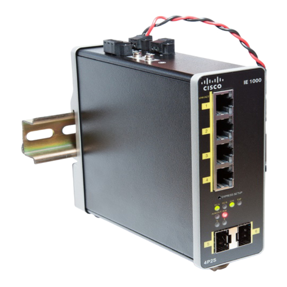
Product Overview Front Panel Overview Switch Models Supported FE Uplink Gig Uplink FE Downlink Model Copper Copper Description IE-1000-4T1T-LM IE1K with total of 5 FE ports 10/100 IE-1000-6T2T-LM IE1K with total of 8 FE ports 10/100 IE-1000-4P2S-LM IE1K with 2 GE SFP, 4 PoE 10/100 with total of 6 ports IE-1000-8P2S-LM IE1K with 2 GE SFP, 8 PoE... -
Page 7: Ports And Slots
In all cases, the attached device must be within 328 feet (100 meters). 100BASE-TX traffic requires Category 5 cable. 10BASE-T traffic can use Category 3 or Category 4 cables. When connecting the switch to workstations, servers, routers, and Cisco IP phones, make sure that the cable is a straight-through cable. -
Page 8: Sfp Modules Supported
For a complete list of supported SFP modules refer to the Data Sheet. Connectors Figure 2 Cisco IE-1000-4P2S-LM top panel shown Alarm connector (PoE Models Only) Power connector DC-A Protective ground connection Power connector DC-B (PoE Models Only) DC Power Connector You connect the DC power to the switch through the top panel connectors. - Page 9 Product Overview Alarm Connector (PoE Models Only) The switch can operate with a single power source or with dual power sources. When both power sources are operational, the switch draws power from the DC source with the higher voltage. If one of the two power sources fail, the other continues to power the switch.
-
Page 10: Express Setup Led
Figure 3 on page 6 on page 8 show the front panel LEDs. Figure 3 LEDs on the Cisco IE 1000 Switch (PoE Models Only) DC A Power connector DC-A LED ALM-OUT (PoE Only) Alarm Out LED DC B (PoE Only) -
Page 11: Power Status Leds
Product Overview LEDs Alarm OUT (PoE Models Only) Color System Status Alarm OUT is not configured, or the switch is off. Green Alarm OUT is configured, no alarm detected. Blinking red Switch has detected a major alarm. Switch has detected a minor alarm. Power Status LEDs The switch can operate with one or two DC power sources. -
Page 12: Poe Status Led
DIN rail and return to the original position to secure the switch to a DIN rail. Figure 4 Cisco IE 1000 Switch Rear Panel Management Options The switch supports these management options: ... -
Page 13: Network Configurations
Product Overview Network Configurations Network Configurations See the switch software configuration guide on Cisco.com for network configuration concepts and examples of using the switch to create dedicated network segments and interconnecting the segments through Gigabit Ethernet connections. - Page 14 Product Overview Network Configurations...
-
Page 15: Switch Installation
The interior of the enclosure must be accessible only by the use of a tool. Subsequent sections of this publication might contain additional information regarding specific enclosure-type ratings that are required to comply with certain product safety certifications. Cisco Systems, Inc. www.cisco.com... -
Page 16: General Guidelines
Before installation, observe these general guidelines: Caution: Proper ESD protection is required whenever you handle Cisco equipment. Installation and maintenance personnel should be properly grounded by using ground straps to eliminate the risk of ESD damage to the switch. Do not touch connectors or pins on component boards. Do not touch circuit components inside the switch. When not in use, store the equipment in appropriate static-safe packaging. -
Page 17: Supported Power Supplies
Switch Installation Connecting to Power Crimping tool (such as Thomas & Bett part number WT4000, ERG-2001, or equivalent). 10-gauge copper ground wire. For DC power connections, use UL- and CSA-rated, style 1007 or 1569 twisted-pair copper appliance wiring material (AWM) wire. - Page 18 Switch Installation Connecting to Power Warning: This equipment must be grounded. Never defeat the ground conductor or operate the equipment in the absence of a suitably installed ground conductor. Contact the appropriate electrical inspection authority or an electrician if you are uncertain that suitable grounding is available. Statement 1024 Warning: This equipment is intended to be grounded to comply with emission and immunity requirements.
- Page 19 Switch Installation Connecting to Power Figure 6 Ground-Lug Screw Attach the other end of the ground wire to a grounded bare metal surface, such as a ground bus, a grounded DIN rail, or a grounded bare rack. Connecting the Power Supply to a DC Power Source You can also connect the power converter to a DC power source.
-
Page 20: Wiring The Dc Power Source
Switch Installation Connecting to Power Insert the other end of the exposed ground wire lead into the earth-ground wire connection on the power converter terminal block. Note that the position of the power converter may vary on different switch models. Tighten the earth-ground wire connection terminal block screw. - Page 21 Switch Installation Connecting to Power Using an 18-gauge wire-stripping tool, strip each of the two twisted pair wires coming from each DC-input power source to 0.25 inch (6.3 mm) ± 0.02 inch (0.5 mm). Do not strip more than 0.27 inch (6.8 mm) of insulation from the wire.
-
Page 22: Attaching The Power Connectors To The Switch
Switch Installation Connecting to Power Attaching the Power Connectors to the Switch To attach the power connectors to the front panel of the switch, follow these steps: Insert one power connector into the DC-A receptacle on the switch front panel, and the other into the DC-B receptacle. -
Page 23: Installing The Switch On A Din Rail
Switch Installation Installing the Switch Installing the Switch This section describes how to install the switch: Installing the Switch on a DIN Rail, page 19 Removing the Switch from a DIN Rail, page 20 Warning: This equipment is supplied as “open type” equipment. It must be mounted within an enclosure that is suitably designed for those specific environmental conditions that will be present and appropriately designed to prevent personal injury resulting from accessibility to live parts. -
Page 24: Removing The Switch From A Din Rail
Switch Installation Installing the Switch Figure 9 Switch mounted on DIN Rail Push the switch toward the DIN rail to cause the spring-loaded latch at the bottom rear of the switch to move down, and snap into place. After the switch is mounted on the DIN rail, connect the power and alarm wires, as described in Connecting Alarm Circuits, page Removing the Switch from a DIN Rail... -
Page 25: Connecting Alarm Circuits
Switch Installation Connecting Alarm Circuits Figure 10 Releasing the Spring-Loaded Latch from the DIN Rail Remove the switch from the DIN rail. Connecting Alarm Circuits After the switch is installed, you are ready to connect the DC power and alarm connections. ... - Page 26 Switch Installation Connecting Alarm Circuits Label Connection Alarm Output Normally Closed (NC) connection Alarm Output Common connection -||- Alarm Output Normally Open (NO) connection Warning: Explosion Hazard—Do not connect or disconnect wiring while the field-side power is on; an electrical arc can occur.
-
Page 27: Attaching The Alarm Connector To The Switch
Switch Installation Connecting Destination Ports Insert the exposed wires for the external alarm device into the connections based on an alarm input or output circuit setup. Use a ratcheting torque flathead screwdriver to tighten the alarm connector captive screw (above the installed wire leads) to 2 in-lb (0.226 Nm).) Caution: Do not over-torque the power and alarm connectors’... -
Page 28: Installing And Removing Sfp Modules
To connect to 10BASE-T, or 100BASE-T devices, follow these steps: When connecting to workstations, servers, routers, and Cisco IP phones, connect a straight-through cable to an RJ-45 connector on the front panel. Connect the other end of the cable to an RJ-45 connector on the other device. The port LED turns on when both the switch and the connected device have established a link. -
Page 29: Removing Sfp Modules From Sfp Module Slots
Switch Installation Connecting Destination Ports Figure 12 SFP Module with a Bale-Clasp Latch To insert an SFP module into the SFP module slot: Attach an ESD-preventive wrist strap to your wrist and to a grounded bare metal surface. Find the send (TX) and receive (RX) markings that identify the correct side of the SFP module. On some SFP modules, the send and receive (TX and RX) markings might be replaced by arrows that show the direction of the connection, either send or receive (TX or RX). -
Page 30: Connecting To Sfp Modules
Switch Installation Where to Go Next Connecting to SFP Modules This section describes how to connect to a fiber-optic SFP port. For instructions on how to install or remove an SFP module, see Installing and Removing SFP Modules, page Warning: Class 1 laser product. -
Page 31: Running Express Setup
Connect power to the switch. See the wiring instructions in the “Grounding the Switch” section and the “Wiring the DC Power Source” section on page 19. Power on or reset the IE 1000: — Use LEDs to monitor boot progress... - Page 32 Running Express Setup Ensure the IE 1000 is in default factory mode. Skip to next step if freshly out of the box If not freshly out of the package, use a paper clip to reset the switch by depressing the express setup button for 15 - 20 seconds until the EXP LED alternates green - red;...
- Page 33 (Optional) Default Gateway: Enter the IP address of the router. Note: The Device manager will not allow you to exit the express setup page if the static IP address of the IE 1000 and the Default Gateway are not in the same subnet.
- Page 34 After power cycling, the IE 1000 will not act as DHCP server. DHCP Server behavior is special to Express Setup. to reconnect to the IE 1000 after the power cycle you will need to A) configure a static IP Address on your PC that is in the same subnet as the IP Address you just assigned, or B) connect to the new IP Address of the IE 1000 from the network.
- Page 35 Running Express Setup — Confirm that the computer that you are using to access the switch has network connectivity by connecting it to a well known web server in your network. If there is no network connection, troubleshoot the network settings on the computer.
- Page 36 Running Express Setup...
-
Page 37: Troubleshooting
Verify that you have the correct fiber-optic cable for the distance and port type. Make sure that the connected device ports match and use the same type encoding, optical frequency, and fiber type. Determine if a copper crossover cable was used when a straight-through was required or the reverse. Cisco Systems, Inc. www.cisco.com... - Page 38 Verify the cable type. See Cable and Connectors, page SFP Module Use only Cisco SFP modules. Each Cisco module has an internal serial EEPROM that is encoded with security information. This encoding verifies that the module meets the requirements for the switch. ...
-
Page 39: Resetting The Switch
Troubleshooting Resetting the Switch Switch Performance Speed, Duplex, and Autonegotiation Port statistics that show a large amount of alignment errors, frame check sequence (FCS), or late-collisions errors, might mean a speed or duplex mismatch. A common issue occurs when duplex and speed settings are mismatched between two switches, between a switch and a router, or between the switch and a workstation or server. -
Page 40: Finding The Switch Serial Number
Finding the Switch Serial Number Finding the Switch Serial Number If you contact Cisco Technical Assistance, you need to know the serial number of your switch. The serial number is on the compliance label on the right-hand side of the switch. See... -
Page 41: Cable And Connectors
Label 4 5 6 7 8 Note: For the two models of IE 1000 switch that support PoE, connector pins 4 and 5 supply +48 VDC and pins 7 and 8 are the DC voltage return lines. SFP Module Connectors... -
Page 42: Cables And Adapters
Cable and Connectors Cables and Adapters Figure 3 Fiber-Optic SFP Module LC Connector Warning: Invisible laser radiation may be emitted from disconnected fibers or connectors. Do not stare into beams or view directly with optical instruments. Statement 1051 Cables and Adapters ... - Page 43 Cable and Connectors Cables and Adapters Figure 5 Two Twisted-Pair Crossover Cable Schematic for 10/100 Ports Switch Switch 3 TD+ 3 TD+ 6 TD– 6 TD– 1 RD+ 1 RD+ 2 RD– 2 RD– Figure 6 Identifying a Crossover Cable Pin 1 Pin 3 Pin 6...
- Page 44 Cable and Connectors Cables and Adapters...
-
Page 45: Hazardous Location Installation Information
Hazardous Location Installation Information This appendix provides hazardous location installation information for the Cisco IE 1000 switches. Hazardous Area Installation Warnings Warning: Before working on equipment that is connected to power lines, remove jewelry (including rings, necklaces, and watches). Metal objects will heat up when connected to power and ground and can cause serious burns or weld the metal object to the terminals. - Page 46 Hazardous Location Installation Information Hazardous Area Installation Warnings Warning: When you connect or disconnect the power and/or alarm connector with power applied, an electrical arc can occur. This could cause an explosion in hazardous area installations. Be sure that all power is removed from the switch and any other circuits.
-
Page 47: North American Hazardous Location Approval
– Top and bottom: 2.0 in. (50.8 mm) – Sides: 1.0 in. (25.4 mm) – Front: 2.0 in. (50.8 mm) Contact your Cisco Technical Assistance Centre (TAC) if tighter spacings are required. Caution: The device is intended for vertical installations only. -
Page 48: Hazardous Locations Standards
Hazardous Location Installation Information Hazardous Locations Standards Hazardous Locations Standards Hazardous location standards for the Cisco IE 1000 switches: The following standards were used for the hazardous locations approvals and certifications: ANSI/ASA 12.12.01-2013 CAN/CSA C22.2 No. 60079-0: 11 CAN/CSA C22.2 No. 60079-15:12 CSA C22.2 No. -
Page 49: Technical Specifications
This appendix provides the technical specification for the Cisco IE 1000 switches. Operating Temperature Specifications Table 1 on page 45 lists the Operating Temperatures (measured inside enclosure, 1” below switch) for the Cisco IE 1000 switches. Table 1 Operation Temperature Specification for the Cisco IE 1000 Switches... - Page 50 Technical Specifications Technical Specifications Operating temperature Non-POE (Measured inside enclosure, 1” below -34C to +74C -16C to +74C switch) • -40C to +70C (40 lfm Vented • -20C to +70C (40 lfm Vented Enclosure Operating) Enclosure Operating) • -40C to +60C (Sealed Enclosure •...
-
Page 51: Alarm Ratings
Technical Specifications Alarm Ratings Alarm Ratings The alarm ratings for the Cisco IE 1000 switches are below. Table 3 Cisco IE 1000 Alarm Ratings Alarm Ratings Specification Alarm output electrical specification 1.0 A @ 24 VDC or 0.5 A @ 48 VDC... - Page 52 Technical Specifications Alarm Ratings...
Need help?
Do you have a question about the IE 1000 and is the answer not in the manual?
Questions and answers