Cisco IE 3000 Hardware Installation Manual
Hide thumbs
Also See for IE 3000:
- Software configuration manual (760 pages) ,
- Hardware installation manual (170 pages) ,
- Getting started manual (32 pages)
Table of Contents
Advertisement
Quick Links
Advertisement
Table of Contents

Related Manuals for Cisco IE 3000


Summary of Contents for Cisco IE 3000
- Page 1 Cisco IE 3000 Switch Hardware Installation Guide First Published: March 2013 Last Updated: December 23, 2014 Cisco Systems, Inc. www.cisco.com Cisco has more than 200 offices worldwide. Addresses, phone numbers, and fax numbers are listed on the Cisco website at www.cisco.com/go/offices.
- Page 2 OR ITS SUPPLIERS HAVE BEEN ADVISED OF THE POSSIBILITY OF SUCH DAMAGES. Cisco and the Cisco logo are trademarks or registered trademarks of Cisco and/or its affiliates in the U.S. and other countries. To view a list of Cisco trademarks, go to this URL: www.cisco.com/go/trademarks.
-
Page 3: Table Of Contents
1-16 Dual-Purpose Port LEDs 1-16 100BASE-X SFP Port LEDs 1-17 PoE Status LED 1-17 10/100BASE-T PoE and Non-PoE Port LEDs 1-17 Compact Flash Memory Card 1-18 Rear-Panel Description 1-19 Power Converter (Optional) 1-20 Cisco IE 3000 Switch Hardware Installation Guide... - Page 4 Wiring the External Alarms 2-37 Connecting Destination Ports 2-40 Connecting to 10/100 and 10/100/1000 Ports 2-40 Installing and Removing SFP Transceivers 2-41 Installing SFP Transceivers into Module Ports 2-42 Removing SFP Transceivers from Module Ports 2-43 Cisco IE 3000 Switch Hardware Installation Guide...
- Page 5 Port and Interface Settings Ping End Device Spanning Tree Loops Verify Switch Performance Speed, Duplex, and Autonegotiation Autonegotiation and NIC Cabling Distance How to Clear the Switch IP Address and Configuration How to Recover Passwords Cisco IE 3000 Switch Hardware Installation Guide...
- Page 6 Connecting Power and Alarm Circuits B-39 Information about the Sealed Relay Device B-40 Wiring the Protective Ground and DC Power B-40 Wiring the External Alarms B-41 Connecting Destination Ports B-44 Connecting to 10/100 and 10/100/1000 Ports B-44 Cisco IE 3000 Switch Hardware Installation Guide...
- Page 7 PoE Expansion Module Ports (IEM-3000-4PC and IEM-3000-4PC-4TC Only) SFP Transceiver Ports Dual-Purpose Ports Console Port Cable and Adapter Specifications SFP Transceiver Cable Specifications Two Twisted-Pair Cable Pinouts Four Twisted-Pair Cable Pinouts for 1000BASE-T Ports Crossover Cable and Adapter Pinouts C-10 Cisco IE 3000 Switch Hardware Installation Guide...
- Page 8 Configuring the Switch with the CLI-Based Setup Program A P P E N D I X Accessing the CLI from the Console Port Entering the Initial Configuration Information IP Settings Completing the Setup Program Cisco IE 3000 Switch Hardware Installation Guide...
-
Page 9: Preface
We assume that you are familiar with the concepts and terminology of Ethernet and local area networking. Purpose This guide documents the hardware features of the Cisco IE 3000 switches. It describes the physical and performance characteristics of each switch, explains how to install a switch, and provides troubleshooting information. -
Page 10: Related Publications
Statement 1071 The safety warnings for this product are translated into several languages in the Regulatory Compliance and Safety Information for the Cisco IE 3000 Switch that ships with the product. The EMC regulatory statements are also included in that guide. -
Page 11: Overview
C H A P T E R Overview This chapter describes the Cisco Industrial Ethernet (IE) 3000 switch, hereafter referred to as the switch, and covers these topics: Overview, page 1-1 • Switch Models, page 1-2 • Front-Panel Description, page 1-2 •... -
Page 12: Switch Models
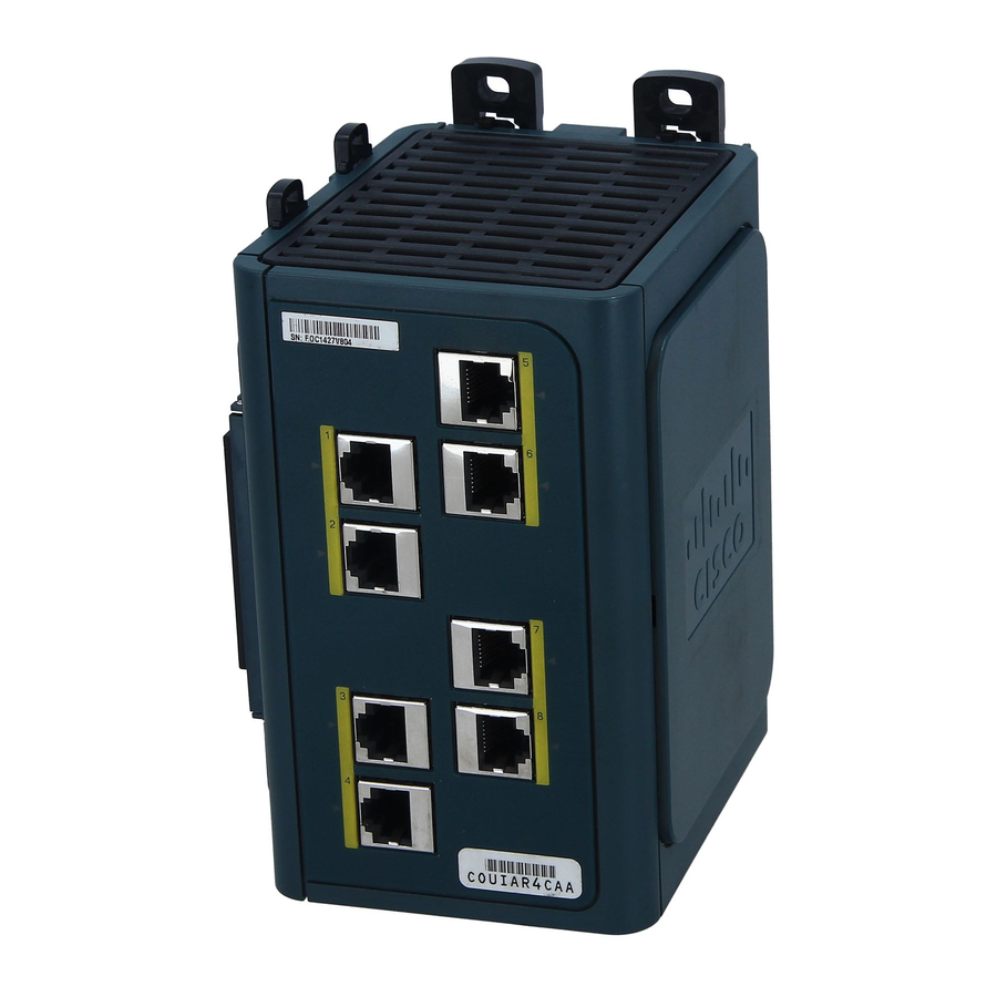
Cisco IE-3000-8TC are the switch models, and the Cisco IEM-3000-8TM and the Cisco IEM-3000-8FM are expansion modules that you can connect to increase the number of ports. For instructions on how to connect the expansion modules to the switch, see the “Adding Modules to the... - Page 13 Cisco IE-3000-8TC Switch Power and relay connectors 10/100 ports Console port Protective ground connection Dual-purpose ports Figure 1-2 Cisco IE-3000-4TC Switch Power and relay connectors 10/100 ports Console port Protective ground connection Dual-purpose ports Cisco IE 3000 Switch Hardware Installation Guide...
- Page 14 Chapter 1 Overview Front-Panel Description Figure 1-3 Cisco IEM-3000-8TM Expansion Module 10/100 ports Figure 1-4 Cisco IEM-3000-8FM Expansion Module 100BASE-FX ports Cisco IE 3000 Switch Hardware Installation Guide...
- Page 15 Chapter 1 Overview Front-Panel Description Figure 1-5 Cisco IEM-3000-4SM Expansion Module 100BASE-X SFP ports Figure 1-6 Cisco IEM-3000-8SM Expansion Module 100BASE-X SFP ports Cisco IE 3000 Switch Hardware Installation Guide...
- Page 16 Chapter 1 Overview Front-Panel Description Figure 1-7 Cisco IEM-3000-4PC PoE Expansion Module DC Input terminal block PoE ports POE STATUS LED Cisco IE 3000 Switch Hardware Installation Guide...
- Page 17 Chapter 1 Overview Front-Panel Description Figure 1-8 Cisco IEM-3000-4PC-4TC PoE Expansion Module 10/100 Non-PoE ports POE STATUS LED DC-Input terminal block PoE ports Cisco IE 3000 Switch Hardware Installation Guide...
-
Page 18: 10/100 Ports
In all cases, the attached device must be within 328 feet (100 meters). 100BASE-TX traffic requires Category 5 cable. 10BASE-T traffic can use Category 3 or Category 4 cables. When connecting the switch to workstations, servers, routers, and Cisco IP Phones, be sure that the cable is a straight-through cable. - Page 19 • GLC-LH-MMD with DOM support GLC-ZX-SMD with DOM support • For the most up-to-date list of supported SFP models for Cisco Industrial Ethernet switches, see http://www.cisco.com/en/US/docs/interfaces_modules/transceiver_modules/compatibility/matrix/OL_ 6981.html#wp138176 For information about SFP modules, see your SFP module documentation and the “Installing and Removing SFP Transceivers”...
-
Page 20: 100Base-Fx Ports
The relay itself is normally open, so under power failure conditions, the contacts are open. From the CLI, you can associate any alarm condition with one or with both alarm relays. Cisco IE 3000 Switch Hardware Installation Guide 1-10... -
Page 21: Console Port
If you want to connect a switch to a terminal, you need to provide an RJ-45-to-DB-25 female DTE adapter. You can order a kit (part number ACS-DSBUASYN=) with that adapter from Cisco Systems. For console-port and adapter-pinout information, see the “Two Twisted-Pair Cable Pinouts”... -
Page 22: Setup Led
Chapter 1 Overview Front-Panel Description Figure 1-10 LEDs on the Cisco IE 3000 Switch Express setup button Dual-purpose uplink port LED System LED Pwr B LED Alarm LED Pwr A LED Setup LED Port LED Figure 1-11 LEDs on the Cisco IEM-3000-8TM Module... - Page 23 LEDs on the Cisco IEM-3000-8FM Module 100BASE -FX port LEDs Figure 1-13 LEDs on the Cisco IEM-3000-8SM Module 100BASE-X port LEDs The port numbering sequence is the same for the IEM-3000-4SM expansion module. Note Cisco IE 3000 Switch Hardware Installation Guide 1-13...
- Page 24 Alarm Status LED Color System Status Alarms are not configured, or the switch is off. Green Alarms are configured. Blinking red Switch has detected a major alarm. Switch has detected a minor alarm. Cisco IE 3000 Switch Hardware Installation Guide 1-14...
-
Page 25: Power Status Led
System Status No link. Solid green Link present. Blinking green Activity. Port is sending or receiving data. Blinking A link blocked by Spanning Tree Protocol (STP) is amber sending or receiving data. Cisco IE 3000 Switch Hardware Installation Guide 1-15... -
Page 26: 100Base-Fx Port Status Leds
The LED colors have the same meanings as described in Table 1-7. Figure 1-14 Dual-Purpose Port LEDs RJ-45 connector SFP module port in-use LED RJ-45 port in-use LED 4 SFP module slot Cisco IE 3000 Switch Hardware Installation Guide 1-16... -
Page 27: 100Base-X Sfp Port Leds
Caution Noncompliant cabling or powered devices can cause a PoE port fault. Use only standard-compliant cabling to connect Cisco prestandard IP Phones and wireless access points or IEEE 802.3af-compliant devices. You must remove any cable or device that causes a PoE fault. -
Page 28: Compact Flash Memory Card
See Figure 1-15. For more information on inserting and removing the compact flash memory card, see the “Installing or Note Removing the Compact Flash Memory Card” section on page 2-12. Cisco IE 3000 Switch Hardware Installation Guide 1-18... -
Page 29: Rear-Panel Description
Compact Flash Memory Card Slot Bottom of switch You can obtain replacement flash memory cards (CF-IE3000=) by calling Cisco Technical Support. Note Rear-Panel Description The rear panel of the switch, modules, and power converter have latches for installation on either a DIN rail or a wall. -
Page 30: Power Converter (Optional)
Note The power converter (PWR-IE3000-AC=) is sold separately. You can get a replacement power cable (PWR-IE3000-CLP=) by calling Cisco Technical Support. For installation and connection procedures for the power converter, see the “Connecting the Switch to the Power Converter” section on page 2-48. -
Page 31: Ac-Input Power Supply (Optional)
Status LED AC-Input Power Supply (Optional) A 50 W AC-input power supply is available as an option for the IE 3000 switch. The power supply comes in two styles: PWR-IE50W-AC—An AC-input power supply with a terminal block connector for the source AC •... -
Page 32: Management Options
Cisco Network Assistant is a PC-based network management GUI application optimized for LANs of small and medium-sized businesses. Through a GUI, users can configure and manage switch clusters or standalone switches. Cisco Network Assistant is available at no cost and can be downloaded from this URL: http://www.cisco.com/en/US/products/ps5931/tsd_products_support_series_home.html... -
Page 33: Network Configurations
Cisco IOS CLI • The switch CLI is based on Cisco IOS software and is enhanced to support desktop-switching features. You can fully configure and monitor the switch. You can access the CLI either by connecting your management station directly to the switch management port, or a console port, or by using Telnet from a remote management station. - Page 34 Chapter 1 Overview Network Configurations Cisco IE 3000 Switch Hardware Installation Guide 1-24...
-
Page 35: Preparing For Installation
• Where to Go Next, page 2-58 • Preparing for Installation This section provides information about these topics: Warnings, page 2-2 • Installation Guidelines, page 2-3 • Verifying Package Contents, page 2-5 • Cisco IE 3000 Switch Hardware Installation Guide... -
Page 36: Warnings
Statement 1040 Warning For connections outside the building where the equipment is installed, the following ports must be connected through an approved network termination unit with integral circuit protection. 10/100/1000 Ethernet Statement 1044 Cisco IE 3000 Switch Hardware Installation Guide... -
Page 37: Installation Guidelines
Other Guidelines These are other installation guidelines: Proper ESD protection is required whenever you handle Cisco equipment. Installation and Caution maintenance personnel should be properly grounded by using ground straps to eliminate the risk of ESD damage to the switch. - Page 38 Connect the unit only to a Class 2 DC power source. • This equipment is only suitable for use in Class I, Division 2, Groups A, B, C, D, or nonhazardous Caution locations. Cisco IE 3000 Switch Hardware Installation Guide...
-
Page 39: Verifying Package Contents
If you want to connect a terminal to the switch console port, you need to provide an RJ-45-to-DB-25 female DTE adapter. You can order a kit (part number ACS-DSBUASYN=) with that adapter from Cisco. For multimode (MM) connections, you can connect a 100BASE-FX port to a port on a target device by using an dual-LC connector. - Page 40 Chapter 2 Switch Installation Adding Modules to the Switch Table 2-1 Cisco IE-3000-4TC and Cisco IE-3000-8TC Switch Expansion Module Configurations and Port Types Expansion Module Configurations Port Types and Quantity (Including Switch Ports) Expansion Module 1 Expansion Module 2 IE-3000-4TC Switch IE-3000-8TC Switch —...
- Page 41 Chapter 2 Switch Installation Adding Modules to the Switch Table 2-1 Cisco IE-3000-4TC and Cisco IE-3000-8TC Switch Expansion Module Configurations and Port Types (continued) Expansion Module Configurations Port Types and Quantity (Including Switch Ports) Expansion Module 1 Expansion Module 2...
- Page 42 The same sample combinations could also be used with the Cisco IE-3000-8TC switch. Note Due to power constraints, a configuration that includes either IE 3000 switch and two IEM-3000-8SM expansion modules is not supported. Also, no expansion modules can be attached to the right of an IEM-3000-8SM expansion module.
- Page 43 (12 FE and 8 FX ports) ports) Cisco IE-3000-4TC switch with one Cisco Cisco IE-3000-4TC switch with two Cisco IEM-3000-8FM expansion module (4 FE and IEM-3000-8TM expansion modules (20 FE 8 FX ports) ports) Cisco IE 3000 Switch Hardware Installation Guide...
-
Page 44: Connecting Modules
If necessary, use a screwdriver to pry open the side panel. See Figure 2-2. Figure 2-2 Opening the Side Panel of the Cisco IE-3000-8TC Switch Remove the EMI protective cover from the interface connector on the switch. See Figure 2-2. - Page 45 Align the connectors on the switch and the module, and slide the switch and the module together to make Step 4 the connection. See Figure 2-5. Figure 2-5 Connecting the Switch and the Module Push the upper module latches down and the lower latches up. See Figure 2-6. Step 5 Cisco IE 3000 Switch Hardware Installation Guide 2-11...
-
Page 46: Installing Or Removing The Compact Flash Memory Card
DC; however, the site source power voltage must be 48-54VDC. Installing or Removing the Compact Flash Memory Card The switches store Cisco IOS software images and switch configurations on a removable flash memory card. You can replace the switch without reconfiguring it. The switch ships with the compact flash memory card installed. -
Page 47: Verifying Switch Operation
These sections describe the steps required to connect a PC or terminal to the switch console port, to power on the switch, and to observe POST results: Connecting a PC or a Terminal to the Console Port, page 2-14 • Verifying Switch Operation, page 2-13 • Cisco IE 3000 Switch Hardware Installation Guide 2-13... -
Page 48: Connecting A Pc Or A Terminal To The Console Port
To connect a PC to the console port, use the supplied RJ-45-to-DB-9 adapter cable. To connect a terminal to the console port, you need to provide an RJ-45-to-DB-25 female DTE adapter. You can order a kit (part number ACS-DSBUASYN=) with that adapter from Cisco. For console-port and adapter-pinout information, see the “Cable and Adapter Specifications”... -
Page 49: Connecting The Protective Ground And Dc Power
Attach the Power and Relay Connector to the Switch, page 2-23 • The Cisco IE 3000 switch can be used with an optional AC/DC power converter (PWR-IE3000-AC). Note For instructions on how to connect the power converter to the switch, see the “Connecting the Switch to... - Page 50 0.5 in. (12.7 mm) ± 0.02 in. (0.5 mm) 3 Wire lead Insulation Insert the ground wire into the ring terminal lug, and using a crimping tool, crimp the ring terminal to Step 3 the wire. Cisco IE 3000 Switch Hardware Installation Guide 2-16...
- Page 51 Ground cable with ring terminal lug Attach the other end of the ground wire to a grounded bare metal surface, such as a ground bus, a Step 7 grounded DIN rail, or a grounded bare rack. Cisco IE 3000 Switch Hardware Installation Guide 2-17...
-
Page 52: Wiring The Dc Power Source
1569 twisted-pair copper appliance wiring material (AWM) wire (such as Belden part number 9318). To wire the switch to the optional AC/DC converter, go to the “Connecting the Switch to the Power Converter” section on page 2-48. Cisco IE 3000 Switch Hardware Installation Guide 2-18... - Page 53 An exposed wire lead from a DC-input power source can conduct harmful levels of electricity. Be sure that no exposed portion of the DC-input power source wire extends from the power and relay connector. Statement 122 Cisco IE 3000 Switch Hardware Installation Guide 2-19...
- Page 54 (above the installed wire leads) to 2.2 in-lb (0.25 Nm). See Figure 2-15. Do not over-torque the power and relay connector captive screws. The torque should not exceed 2.2 in-lb Caution (0.25 Nm). Cisco IE 3000 Switch Hardware Installation Guide 2-20...
- Page 55 Step 7 using a second power and relay connector. Figure 2-16 shows the completed DC-input wiring on a power and relay connector for a primary power source and an optional secondary power source. Cisco IE 3000 Switch Hardware Installation Guide 2-21...
- Page 56 (Optional) If you plan to connect external alarm devices to the alarm relays and the switch is already Step 8 installed, go to the “Wiring the External Alarms” section on page 2-37. Otherwise, go to the “Verifying Switch Operation” section on page 2-13. Cisco IE 3000 Switch Hardware Installation Guide 2-22...
-
Page 57: Attach The Power And Relay Connector To The Switch
Source DC can come from either the PWR-IE65W-PC-DC, a DC-input power supply, the PWR-IE65W-PC-AC, an AC-input power supply, or from site source DC; however, site source power voltage must be 48–54VDC. Cisco IE 3000 Switch Hardware Installation Guide 2-23... - Page 58 Switch Installation Verifying Switch Operation If you are using the above Cisco PoE AC/DC power supplies, you can power up to 4 PoE or 2 PoE+ devices on each expansion module. To attach site source DC to the expansion module: The equipment is to be connected to a UL Listed, limited power source.
-
Page 59: Running Post
The System LED blinks green as the boot loader verifies the basic functionality of the processing and memory hardware. Assuming all tests pass, the System LED continues to blink green as the Cisco IOS software image loads. If the POST fails, the System LED turns red. -
Page 60: Disconnect Power
To prevent the switch from overheating, ensure these minimum clearances: Caution – Top and bottom: 4.13 in. (105 mm) – Exposed side (not connected to the module): 3.54 in. (90 mm) – Front: 2.56 in. (65 mm) Cisco IE 3000 Switch Hardware Installation Guide 2-26... -
Page 61: Installing The Switch On A Din Rail
The illustrations in this procedure show how to install the switch as a standalone device. The same steps can be used to install a switch with expansion modules on the DIN rail. Cisco IE 3000 Switch Hardware Installation Guide 2-27... - Page 62 Use a flathead screwdriver to press in the space next to the tab on each of the latches and turn the screw Step 1 driver clockwise. See Figure 2-19. Figure 2-19 Unlock the Switch Latch Cisco IE 3000 Switch Hardware Installation Guide 2-28...
- Page 63 Pushing the DIN Rail Latches Out Position the rear panel of the switch directly in front of the DIN rail, making sure that the DIN rail fits Step 3 in the space between the two latches. Cisco IE 3000 Switch Hardware Installation Guide 2-29...
- Page 64 2-21) to the extended Note positions. Otherwise, rotate all of the feet to the recessed positions. Figure 2-22 shows the two DIN rails. You can use either the 7.5-mm or the 15-mm DIN rail. Cisco IE 3000 Switch Hardware Installation Guide 2-30...
-
Page 65: Installing The Switch On The Wall
Read the wall-mounting instructions carefully before beginning installation. Failure to use the Warning correct hardware or to follow the correct procedures could result in a hazardous situation to people and damage to the system. Statement 378 Cisco IE 3000 Switch Hardware Installation Guide 2-31... - Page 66 Switch Installation Installing the Switch If the DIN rail latches are pushed out, push in the DIN rail latches. See Figure 2-23. Step 1 Figure 2-23 Pushing the DIN Rail Latches In Cisco IE 3000 Switch Hardware Installation Guide 2-32...
-
Page 67: Installing The Switch In A Rack
STK-RACKMNT-2955=) to mount the switch in a 19-inch rack. The rack-mounting kit comes with a DIN rail adapter and screws to attach the adapter to the rack. Ask your Cisco representative for details. Cisco IE 3000 Switch Hardware Installation Guide... - Page 68 The 19-inch rack adapter is not intended for application in an industrial environment and therefore it will Note not meet the environmental performance specifications for the Cisco IE 3000 switch. To install the switch in a rack, follow these steps: Use the four Phillips machine screws to securely attach the brackets to the rack.
-
Page 69: Removing The Switch From A Din Rail Or A Rack
Push the DIN rail latches at the top of the switch up, and the latches at the bottom of the switch down. Step 3 Pull the switch out, and release the switch from the DIN rail. See Figure 2-27. Cisco IE 3000 Switch Hardware Installation Guide 2-35... -
Page 70: Connecting Power And Alarm Circuits
Protective Ground and DC Power” section on page 2-15. For instructions on using a power converter for DC power, see the “Connecting the Switch to the Power Converter” section on page 2-48. Cisco IE 3000 Switch Hardware Installation Guide 2-36... -
Page 71: Wiring The External Alarms
Use a ratcheting torque flathead screwdriver to torque the power and relay connector captive screw Step 4 (above the installed wire leads) to 2 in-lb (0.22 Nm). See Figure 2-29 for details. Cisco IE 3000 Switch Hardware Installation Guide 2-37... - Page 72 Torquing the Power and Relay Connector Captive Screws Repeat Step 1 through Step 4 to insert the input and output wires of an additional external alarm device Step 5 into the second power and relay connector. Cisco IE 3000 Switch Hardware Installation Guide 2-38...
- Page 73 See the “Attach the Power and Relay Connector to the Switch” section on page 2-23 for instructions on how to connect the power and relay connector to the front panel. Cisco IE 3000 Switch Hardware Installation Guide 2-39...
-
Page 74: Connecting Destination Ports
To prevent electrostatic-discharge (ESD) damage, follow your normal board and component handling Caution procedures. To connect to 10BASE-T, 100BASE-TX or 1000BASE-T devices, follow these steps: When connecting to workstations, servers, routers, and Cisco IP Phones, connect a straight-through Step 1 cable to an RJ-45 connector on the front panel. See Figure 2-31. -
Page 75: Installing And Removing Sfp Transceivers
These field-replaceable transceivers provide the optical interfaces, send (TX) and receive (RX). You can use any combination of rugged SFP transceiver. See the Cisco IE 3000 release notes for the list of supported SFP transceivers. SFP transceiver types must match on both ends of the network cable and the length of the network cable must not exceed the stipulated cable length for reliable communications. -
Page 76: Installing Sfp Transceivers Into Module Ports
Position the SFP transceiver in front of the port opening. Step 3 Slide the SFP transceiver into the port until you feel the transceiver connector latch into place. See Step 4 Figure 2-33. Cisco IE 3000 Switch Hardware Installation Guide 2-42... -
Page 77: Removing Sfp Transceivers From Module Ports
If the module has a bale-clasp latch, pull the bale out and down to eject the module. If the bale-clasp latch is obstructed and you cannot use your index finger to open it, use a small, flat-blade screwdriver or other long, narrow instrument to open the bale-clasp latch. Cisco IE 3000 Switch Hardware Installation Guide 2-43... -
Page 78: Connecting To Sfp Transceivers
Before connecting to the SFP module, be sure that you understand the port and cabling stipulations in “Preparing for Installation” section on page 2-1. See Appendix C, “Cable and Connectors,” information about the LC on the SFP transceiver. Cisco IE 3000 Switch Hardware Installation Guide 2-44... -
Page 79: Connecting To A Dual-Purpose Port
Only one interface can be active at a time. If both interfaces are connected, the SFP module has priority. For more information about dual-purpose ports, see the “Dual-Purpose Ports” section on page 1-8. Class 1 laser product. Statement 1008 Warning Cisco IE 3000 Switch Hardware Installation Guide 2-45... - Page 80 You can change this setting and configure the port to recognize only an RJ-45 connector or only an SFP module by using the media type interface configuration command. For more information, see the switch command reference. Cisco IE 3000 Switch Hardware Installation Guide 2-46...
-
Page 81: Connecting To 100Base-Fx Ports
Chapter 2 Switch Installation Connecting Destination Ports Connecting to 100BASE-FX Ports Follow these steps to connect a fiber-optic cable to an Cisco IEM-3000-8FM expansion module: Class 1 laser product. Statement 1008 Warning Caution Do not remove the rubber plugs from the SFF module port or the rubber caps from the fiber-optic cable until you are ready to connect the cable. -
Page 82: Connecting To A Poe Port
[power inline wattage <mod> max <4-130> watts] Connecting the Switch to the Power Converter The Cisco IE 3000 switch can be used with an optional AC/DC power converter (PWR-IE3000-AC). These sections describe the steps required to connect the switch to a power converter: Attaching the Power Converter to the Switch, page 2-49 •... -
Page 83: Attaching The Power Converter To The Switch
Pushing the Module Latches Up and Positioning the Hardware , 2.1 A Rtn Ou t (-) Pw r Ou t (+) DC OK 100 -240 V~, 50-6 125 -250 0Hz / , 1.25 A MA X Cisco IE 3000 Switch Hardware Installation Guide 2-49... -
Page 84: Installing The Power Converter On A Din Rail, Wall, Or Rack Adapter
The DC power clip is a prewired cable that connects DC power from the power converter to the switch module. Because the power clip uses the Pwr A connector, you cannot use the alarm connections on that connector. Cisco IE 3000 Switch Hardware Installation Guide 2-50... -
Page 85: Connecting The Power Converter To An Ac Power Source
Power-cord wiring color codes also vary by country. You must to have a qualified electrician select, prepare, and install the appropriate power cord to the power supply. Cisco IE 3000 Switch Hardware Installation Guide 2-51... - Page 86 MA X Ground wire Step 2 Insert the exposed ground wire lead into the power converter ground wire connection. Ensure that only wire with insulation extends from the connector. See Figure 2-43. Cisco IE 3000 Switch Hardware Installation Guide 2-52...
- Page 87 The torque should not exceed 2.2 in-lb (0.25 Nm). Note Replace the plastic cover over the terminal block. Step 6 Connect the other end of the AC power cord to the AC outlet. Step 7 Cisco IE 3000 Switch Hardware Installation Guide 2-53...
-
Page 88: Connecting The Power Converter To A Dc Power Source
Only wire with insulation should extend from the connection. See Figure 2-44. Tighten the earth-ground wire connection terminal block screw. Step 6 The torque should not exceed 2.2 in-lb (0.25 Nm). Note Cisco IE 3000 Switch Hardware Installation Guide 2-54... - Page 89 Connect the red wire to the positive pole of the DC power source, and connect the black wire to the return Step 9 pole. Ensure that each pole has a current-limiting-type fuse rated to at least 600 VAC/DC (such as the KLKD Midget fuse). Cisco IE 3000 Switch Hardware Installation Guide 2-55...
-
Page 90: Applying Power To The Power Converter
2-25. Connecting the Switch to the AC-Input Power Supply The Cisco IE 3000 switch can be used with an optional AC-input power supply (PWR-IE50W-AC or PWR-IE50W-AC-IEC). These sections describe the steps required to connect the switch to the AC-input power supply: Attaching the Power Supply to the Switch, page 2-56 •... -
Page 91: Connecting The Dc Power Clip
To connect source AC to the power supply, plug the AC power cord appliance connector into the power supply AC in connector. Plug the other end of the AC power cord into a dedicated source AC outlet. Cisco IE 3000 Switch Hardware Installation Guide 2-57... -
Page 92: Connecting The Ac Power Cord To The Power Supply
• Start the Cisco Network Assistant application, which is described in the Getting Started with Cisco Network Assistant guide. Through this GUI, you can configure and monitor a switch cluster or an individual switch. - Page 93 Where to Go Next Use the CLI to configure the switch as an individual switch from the console. See the switch • command reference on Cisco.com for information about using the CLI. • Start an SNMP application such as the CiscoView application.
- Page 94 Chapter 2 Start the Common Industrial Protocol (CIP) management tool. You can manage an entire industrial Where to Go Next Cisco IE 3000 Switch Hardware Installation Guide 2-60...
-
Page 95: Chapter 3 Troubleshooting
If the switch fails POST, the System LED turns red. Note POST failures are usually fatal. Contact your Cisco technical support representative if your switch does not pass POST. If you have a terminal connected to the console port, you can also view POST status and test results on the terminal. -
Page 96: Verify Switch Leds
Determine if a crossover cable was used when a straight-through was required or the reverse. Enable auto-MDIX on the switch, or replace the cable. See the “Cable and Adapter Specifications” section on page C-5 for recommended Ethernet cables. Cisco IE 3000 Switch Hardware Installation Guide... -
Page 97: Link Status
Transceiver Issues Use only Cisco SFP modules on the switch. Each Cisco module has an internal serial EEPROM that is encoded with security information. This encoding provides a way for Cisco to identify and validate that the module meets the requirements for the switch. -
Page 98: Spanning Tree Loops
NIC. You can resolve this by upgrading the NIC driver to the latest version available from the manufacture. Cisco IE 3000 Switch Hardware Installation Guide... -
Page 99: Cabling Distance
“How to Clear the Switch IP Address and Configuration” section on page 3-5. The switch software configuration guide provides details about enabling and disabling the password recovery feature and the procedure for recovering passwords. Cisco IE 3000 Switch Hardware Installation Guide... -
Page 100: Finding The Switch Serial Number
Troubleshooting Finding the Switch Serial Number Finding the Switch Serial Number If you contact Cisco Technical Assistance, you need to know the serial number of your switch. See Figure 3-1 Figure 3-2 to find the serial number on your switch or module. See... - Page 101 Chapter 3 Troubleshooting Finding the Switch Serial Number Figure 3-3 Serial Number Location for the Cisco PWR-IE3000-AC Power Converter , 2 .1 A 2 4 V SN: XXXNNNNXXXX u t (- ) R tn O (+ ) O u t...
- Page 102 Chapter 3 Troubleshooting Finding the Switch Serial Number Cisco IE 3000 Switch Hardware Installation Guide...
-
Page 103: Appendix
Cisco IE 3000 switch power converter. The operating temperature for the Cisco IE 3000 switches, expansion modules, and the power convertor varies among environments, based on factors such as the system configuration and enclosure types. - Page 104 • 1 A @ 48 VDC • 2 A @ 24 VDC IEM-3000-4PC and IEM-3000-4PC-4TC: 2.4 A PoE expansion modules receive power from a separate Note power supply or from site DC power. Cisco IE 3000 Switch Hardware Installation Guide...
- Page 105 2. The maximum operating temperature of the switch varies depending on the type of SFP module that you use. Note The technical specifications listed in Table A-2 for the Cisco IE-3000-8TC and IE-3000-4TC switches also apply to the Cisco IE-3000-8TC-E and Cisco IE-3000-4TC-E switches.
- Page 106 Hazardous Locations ANSI/ISA 12.12.01-2011 UL 60079-0, 5th Ed, 2009-10-21 IEC 60079-15, 3rd Ed, 2009-7-17 CSA C22.2 No. 213-M1987 CAN/CSA E60079-15: 02 EN 60079-0:2009 EN 60079-15:2010 IEC 60079-0 4th Edition IEC 60079-15 5th Edition Cisco IE 3000 Switch Hardware Installation Guide...
-
Page 107: Appendix
• Where to Go Next, page B-64 • Preparing for Installation This section provides information about these topics: Warnings, page B-2 • Installation Guidelines, page B-5 • Verifying Package Contents, page B-7 • Cisco IE 3000 Switch Hardware Installation Guide... -
Page 108: Preparing For Installation
Statement 1040 Warning For connections outside the building where the equipment is installed, the following ports must be connected through an approved network termination unit with integral circuit protection. 10/100/1000 Ethernet Statement 1044 Cisco IE 3000 Switch Hardware Installation Guide... -
Page 109: Preparing For Installation B
To verify switch operation, perform POST on the switch in a nonhazardous location before installation. Statement 1065 Use twisted-pair supply wires suitable for 86°F (30°C) above surrounding ambient temperature Warning outside the enclosure. Statement 1067 Cisco IE 3000 Switch Hardware Installation Guide... -
Page 110: North American Hazardous Location Approval
(code de température le plus faible) peut être utilisé pour déterminer le code de température global du système. Les combinaisons d'équipements dans le système sont sujettes à inspection par les autorités locales qualifiées au moment de l'installation. Cisco IE 3000 Switch Hardware Installation Guide... -
Page 111: Emc Environmental Conditions For Products Installed In The European Union
Provision should be made, either in the apparatus or external to the apparatus, to prevent the rated • voltage from being exceeded by transient disturbances of more than 40 percent. Other Guidelines These are other installation guidelines: Cisco IE 3000 Switch Hardware Installation Guide... - Page 112 Appendix B Installation In a Hazardous Environment North American Hazardous Location Approval Proper ESD protection is required whenever you handle Cisco equipment. Installation and Caution maintenance personnel should be properly grounded by using ground straps to eliminate the risk of ESD damage to the switch.
-
Page 113: Verifying Package Contents
If you want to connect a terminal to the switch console port, you need to provide an RJ-45-to-DB-25 female DTE adapter. You can order a kit (part number ACS-DSBUASYN=) with that adapter from Cisco. You can order a kit containing four spare latches (DINCLP-IE3000=) from Cisco. -
Page 114: Expansion Module Configurations
The table also provides a breakdown of the type and quantity of ports for a particular switch expansion module combination. Table B-1 Cisco IE-3000-4TC and Cisco IE-3000-8TC Switch Expansion Module Configurations and Port Types Expansion Module Configurations... - Page 115 Appendix B Installation In a Hazardous Environment Adding Modules to the Switch Table B-1 Cisco IE-3000-4TC and Cisco IE-3000-8TC Switch Expansion Module Configurations and Port Types (continued) Expansion Module Configurations Port Types and Quantity (Including Switch Ports) Expansion Module 1...
- Page 116 Note switch. The same sample combinations could also be used with the Cisco IE-3000-8TC switch. Due to power constraints, a configuration that includes either IE 3000 switch and two IEM-3000-8SM Note expansion modules is not supported. Also, the only expansion modules that can be attached to the right...
- Page 117 IEM-3000-8TM expansion modules (12 FE modules (12 FE and 8 FX ports) ports) IE-3000-4TC switch with one IE-3000-4TC switch with two IEM-3000-8FM expansion module (4 FE and IEM-3000-8TM expansion modules (20 FE 8 FX ports) ports) Cisco IE 3000 Switch Hardware Installation Guide B-11...
-
Page 118: Connecting Modules
See Figure B-2. Figure B-2 Opening the Side Panel of the Cisco IE-3000-8TC Switch Remove the EMI protective cover from the interface connector on the switch. See Figure B-3. Step 2... - Page 119 See Figure B-5. Figure B-5 Connecting the Switch and the Module Push the upper module latches down and the lower latches up. See Figure B-6. Step 5 Cisco IE 3000 Switch Hardware Installation Guide B-13...
-
Page 120: Installing Or Removing The Compact Flash Memory Card
Note Installing or Removing the Compact Flash Memory Card The switches store Cisco IOS software images and switch configurations on a removable flash memory card. You can replace the switch without reconfiguring it. The switch ships with the compact flash memory card installed. -
Page 121: Verifying Switch Operation
These sections describe the steps required to connect a PC or terminal to the switch console port, to power on the switch, and to observe POST results: Connecting a PC or a Terminal to the Console Port, page B-16 • • Verifying Switch Operation, page B-15 Cisco IE 3000 Switch Hardware Installation Guide B-15... -
Page 122: Connecting A Pc Or A Terminal To The Console Port
To connect a PC to the console port, use the supplied RJ-45-to-DB-9 adapter cable. To connect a terminal to the console port, you need to provide an RJ-45-to-DB-25 female DTE adapter. You can order a kit (part number ACS-DSBUASYN=) with that adapter from Cisco. For console-port and adapter-pinout information, see the “Cable and Adapter Specifications”... -
Page 123: Connecting The Protective Ground And Dc Power
Attach the Power and Relay Connector to the Switch, page B-25 • The Cisco IE 3000 switch can be used with an optional AC/DC power converter (PWR-IE3000-AC). Note For instructions on how to connect the power converter to the switch, see the “Connecting the Switch to... -
Page 124: Grounding The Switch
Thomas & Bett part number 10RCR or equivalent. Use a wire-stripping tool to strip the 10- gauge wire to 0.5 inch (12.7 mm) ± 0.02 inch (0.5 mm). See Step 2 Figure B-9. Cisco IE 3000 Switch Hardware Installation Guide B-18... - Page 125 Insert the ground screw into the functional ground screw opening on the front panel. Step 5 Use a ratcheting torque screwdriver to tighten the ground screw and ring terminal lug to the switch front Step 6 panel to 8.5 in-lb. See Figure B-11. Cisco IE 3000 Switch Hardware Installation Guide B-19...
-
Page 126: Wiring The Dc Power Source
This product relies on the building’s installation for short-circuit (overcurrent) protection. Ensure that Warning the protective device is rated not greater than: 5A. Statement 1005 Installation of the equipment must comply with local and national electrical codes. Statement 1074 Warning Cisco IE 3000 Switch Hardware Installation Guide B-20... - Page 127 (6.8 mm) of insulation from the wire. Stripping more than the recommended amount of wire can leave exposed wire from the power and relay connector after installation. Figure B-13 Stripping the Power Connection Wire 0.25 in. (6.3 mm) ± 0.02 in. (0.5 mm) Cisco IE 3000 Switch Hardware Installation Guide B-21...
- Page 128 (above the installed wire leads) to 2.2 in-lb (0.25 Nm). See Figure B-15. Do not over-torque the power and relay connector captive screws. The torque should not exceed 2.2 in-lb Caution (0.25 Nm). Cisco IE 3000 Switch Hardware Installation Guide B-22...
- Page 129 When you are testing the switch, one power connection is sufficient. If you are installing the switch and are using a second power source, repeat Step 4 through Step 7 using a second power and relay connector. Cisco IE 3000 Switch Hardware Installation Guide B-23...
- Page 130 (Optional) If you plan to connect external alarm devices to the alarm relays and the switch is already Step 8 installed, go to the “Wiring the External Alarms” section on page B-41. Otherwise, go to the “Verifying Switch Operation” section on page B-15. Cisco IE 3000 Switch Hardware Installation Guide B-24...
-
Page 131: Attach The Power And Relay Connector To The Switch
When you are installing the switch, secure the wires coming from the power and relay connector so that they cannot be disturbed by casual contact. For example, use tie wraps to secure the wires to the rack. Cisco IE 3000 Switch Hardware Installation Guide B-25... -
Page 132: Attaching Dc Power To The Poe Expansion Modules
PWR-IE65W-PC-AC, an AC-input power supply, or from site source DC; however, site source power voltage must be 48–54VDC. If you are using the above Cisco PoE AC/DC power supplies, you can power up to 4 PoE or 2 PoE+ devices on each expansion module. -
Page 133: Running Post
For instructions on how to connect the DC-input power supply to the PoE expansion module, refer to the Cisco IE 3000 65 W DC-Input Power Supply Installation Note available on cisco.com. For instructions on how to connect the AC-input power supply to the PoE expansion module, refer to the Cisco IE 3000 65 W AC-Input Power Supply Installation Note available on cisco.com. - Page 134 Installation In a Hazardous Environment Verifying Switch Operation functionality of the processing and memory hardware. Assuming all tests pass, the System LED continues to blink green as the Cisco IOS software image loads. If the POST fails, the System LED turns red. Note POST failures are usually fatal.
-
Page 135: Disconnect Power
To prevent the switch from overheating, ensure these minimum clearances: – Top and bottom: 4.13 in. (105 mm) – Exposed side (not connected to the module): 3.54 in. (90 mm) – Front: 2.56 in. (65 mm) Cisco IE 3000 Switch Hardware Installation Guide B-29... - Page 136 The illustrations in this procedure show how to install the switch as a standalone device. The same steps can be used to install a switch with expansion modules on the DIN rail. Cisco IE 3000 Switch Hardware Installation Guide B-30...
- Page 137 Use a tool such as a flathead screw driver to press in the space next to the tab on each of the latches and Step 1 turn the screw driver clockwise. See Figure B-19. Figure B-19 Unlock the Switch Latch Cisco IE 3000 Switch Hardware Installation Guide B-31...
- Page 138 Pushing the DIN Rail Latches Out Position the rear panel of the switch directly in front of the DIN rail, making sure that the DIN rail fits Step 3 in the space between the two latches. Cisco IE 3000 Switch Hardware Installation Guide B-32...
- Page 139 B-21) to the extended Note positions. Otherwise, rotate all of the feet to the recessed positions. Figure B-22 shows the two DIN rails. You can use either the 7.5-mm or the 15-mm DIN rail. Cisco IE 3000 Switch Hardware Installation Guide B-33...
- Page 140 Read the wall-mounting instructions carefully before beginning installation. Failure to use the Warning correct hardware or to follow the correct procedures could result in a hazardous situation to people and damage to the system. Statement 378 Cisco IE 3000 Switch Hardware Installation Guide B-34...
- Page 141 Installation In a Hazardous Environment Installing the Switch If the DIN rail latches are pushed out, push in the DIN rail latches. See Figure B-23. Step 1 Figure B-23 Pushing the DIN Rail Latches In Cisco IE 3000 Switch Hardware Installation Guide B-35...
-
Page 142: Installing The Switch In A Rack
STK-RACKMNT-2955=) to mount the switch in a 19-inch rack. The rack-mounting kit comes with a DIN rail adapter and screws to attach the adapter to the rack. Ask your Cisco representative for details. Cisco IE 3000 Switch Hardware Installation Guide... - Page 143 Note The 19-inch rack adapter is not intended for application in an industrial environment and therefore it will not meet the environmental performance specifications for the Cisco IE 3000 switch. To install the switch in a rack, follow these steps: Use the four Phillips machine screws to securely attach the brackets to the rack.
-
Page 144: Removing The Switch From A Din Rail Or A Rack
Push the DIN rail latches at the top of the switch up and the latches at the bottom of the switch down. Step 3 Pull the switch out, and release the switch from the DIN rail. See Figure B-27. Cisco IE 3000 Switch Hardware Installation Guide B-38... -
Page 145: Connecting Power And Alarm Circuits
After the switch is installed, you are ready to connect the DC power and alarm relays. Information about the Sealed Relay Device, page B-40 • • Wiring the Protective Ground and DC Power, page B-40 • Wiring the External Alarms, page B-41 Cisco IE 3000 Switch Hardware Installation Guide B-39... -
Page 146: Information About The Sealed Relay Device
Protective Ground and DC Power” section on page B-17. For instructions on using a power converter for DC power, see the “Connecting the Switch to the Power Converter” section on page B-52. Cisco IE 3000 Switch Hardware Installation Guide B-40... -
Page 147: Wiring The External Alarms
Insert the exposed wires for the external alarm device into the two connections labeled A. See Figure B-28. Figure B-28 Inserting Relay Wires into the Power and Relay Connector External device, relay wire A connection 1 External device, relay wire A connection 2 Cisco IE 3000 Switch Hardware Installation Guide B-41... - Page 148 Torquing the Power and Relay Connector Captive Screws Repeat Step 1 through Step 4 to insert the input and output wires of an additional external alarm device Step 5 into the second power and relay connector. Cisco IE 3000 Switch Hardware Installation Guide B-42...
- Page 149 See the “Attach the Power and Relay Connector to the Switch” section on page B-25 for instructions on how to connect the power and relay connector to the front panel. Cisco IE 3000 Switch Hardware Installation Guide B-43...
-
Page 150: Connecting Destination Ports
To prevent electrostatic-discharge (ESD) damage, follow your normal board and component handling Caution procedures. When connecting to workstations, servers, routers, and Cisco IP Phones, connect a straight-through Step 1 cable to an RJ-45 connector on the front panel. See Figure B-31. -
Page 151: Installing And Removing Sfp Transceivers
These sections describe how to install and remove SFP transceivers. SFP transceivers are inserted into SFP transceiver sockets on the front of the switch or the Cisco IEM-3000-4SM or Cisco IEM-3000-8SM expansion modules. These field-replaceable modules provide the optical interfaces, send (TX) and receive (RX). -
Page 152: Installing Sfp Transceivers Into Module Ports
You can populate the switch or expansion module ports with a combination of rugged SFP transceiver types. Not all SFP transceiver types are supported. See the Cisco IE 3000 release notes for the list of supported SFP transceiver. SFP transceiver types must match on both ends of the network cable and the length of thenetwork cable must not exceed the stipulated cable length for reliable communications. -
Page 153: Removing Sfp Transceivers From Module Ports
If the SFP transceiver has a bale-clasp latch, pull the bale out and down to eject the transceiver. If the bale-clasp latch is obstructed and you cannot use your index finger to open it, use a small, flat-blade screwdriver or other long, narrow instrument to open the bale-clasp latch. Cisco IE 3000 Switch Hardware Installation Guide B-47... -
Page 154: Connecting To Sfp Transceivers
Before connecting to the SFP transceiver, be sure that you understand the port and cabling stipulations in the “Preparing for Installation” section on page B-1. See Appendix C, “Cable and Connectors,” information about the LC connector on the SFP transceiver. Cisco IE 3000 Switch Hardware Installation Guide B-48... -
Page 155: Connecting To A Dual-Purpose Port
Only one interface can be active at a time. If both interfaces are connected, the SFP module has priority. For more information about dual-purpose ports, see the “Dual-Purpose Ports” section on page 1-8. Class 1 laser product. Statement 1008 Warning Cisco IE 3000 Switch Hardware Installation Guide B-49... - Page 156 You can change this setting and configure the port to recognize only an RJ-45 connector or only an SFP module by using the media type interface configuration command. For more information, see the switch command reference. Cisco IE 3000 Switch Hardware Installation Guide B-50...
-
Page 157: Connecting To 100Base-Fx Ports
Appendix B Installation In a Hazardous Environment Connecting Destination Ports Connecting to 100BASE-FX Ports Follow these steps to connect a fiber-optic cable to an Cisco IEM-3000-8FM expansion module: Class 1 laser product. Statement 1008 Warning Caution Do not remove the rubber plugs from the SFF module port or the rubber caps from the fiber-optic cable until you are ready to connect the cable. -
Page 158: Connecting To A Poe Port
(2 ports total) Connecting the Switch to the Power Converter The Cisco IE 3000 switch can be used with an optional AC/DC power converter (PWR-IE3000-AC). These sections describe the steps required to connect the switch to a power converter: •... - Page 159 Remove the left side panel of the switch by firmly grasping both sides of it in the middle and pulling it Step 1 outward. If necessary, use a screwdriver to open the side panel. See Figure B-38. Figure B-38 Opening the Left Side Panel of the Switch Cisco IE 3000 Switch Hardware Installation Guide B-53...
- Page 160 Rtn B Mino r Alarm Expr ess Setu Syste m Pwr A Alarm Pwr B Setu p 100 -240 V~, 50-6 125 -250 0Hz / , 1.25 A Cis co Ca tal Cisco IE 3000 Switch Hardware Installation Guide B-54...
-
Page 161: Installing The Power Converter On A Din Rail, Wall, Or Rack Adapter
Position the power clip so that the two-pin connector is over the power converter and the four-pin connector is over the switch Pwr A connector, and then slide the power clip into these two connectors. Figure B-41. Cisco IE 3000 Switch Hardware Installation Guide B-55... -
Page 162: Connecting The Power Converter To An Ac Power Source
Power-cord wiring color codes also vary by country. You must to have a qualified electrician select, prepare, and install the appropriate power cord to the power supply. Use copper conductors only, rated at a minimum temperature of 167°F (75°C). Note Cisco IE 3000 Switch Hardware Installation Guide B-56... - Page 163 MA X Ground wire Insert the exposed ground wire lead into the power converter ground wire connection. Make sure that Step 2 only wire with insulation extends from the connector. See Figure B-43. Cisco IE 3000 Switch Hardware Installation Guide B-57...
- Page 164 The torque should not exceed 2.2 in-lb (0.25 Nm). Note Replace the plastic cover over the terminal block. Step 6 Connect the other end of the AC power cord to the AC outlet. Step 7 Cisco IE 3000 Switch Hardware Installation Guide B-58...
-
Page 165: Connecting The Power Converter To A Dc Power Source
Only wire with insulation should extend from the connection. See Figure B-44. Step 6 Tighten the earth-ground wire connection terminal block screw. The torque should not exceed 2.2 in-lb (0.25 Nm). Note Cisco IE 3000 Switch Hardware Installation Guide B-59... - Page 166 Connect the red wire to the positive pole of the DC power source, and connect the black wire to the return Step 9 pole. Ensure that each pole has a current-limiting-type fuse rated to at least 600 VAC/DC (such as the KLKD Midget fuse). Cisco IE 3000 Switch Hardware Installation Guide B-60...
-
Page 167: Applying Power To The Power Converter
B-27. Connecting the Switch to the AC-Input Power Supply The Cisco IE 3000 switch can be used with an optional AC-input power supply (PWR-IE50W-AC or PWR-IE50W-AC-IEC). These sections describe the steps required to connect the switch to the AC-input power supply: Attaching the Power Supply to the Switch, page B-61 •... -
Page 168: Installing The Ac-Input Power Supply On A Din Rail, Wall, Or Rack Adapter
Use a ratcheting torque flathead screwdriver to tighten the captive screw to 2.2 in-lb (0.25 Nm). Step 3 Do not over-torque the power and relay connector captive screws. The torque should not exceed 2.2 in-lb Caution (0.25 Nm). Cisco IE 3000 Switch Hardware Installation Guide B-62... -
Page 169: Connecting The Ac-Input Power Supply To An Ac Power Source
Ensure that only wire with insulation extends from the connectors. Tighten the line and neutral terminal block screws. Step 6 Note The torque should not exceed 2.2 in-lb (0.25 Nm). Cisco IE 3000 Switch Hardware Installation Guide B-63... -
Page 170: Where To Go Next
• Start the Cisco Network Assistant application, which is described in the Getting Started with Cisco Network Assistant guide. Through this GUI, you can configure and monitor a switch cluster or an individual switch. - Page 171 This appendix describes the switch ports and the cables and adapters that you use to connect the switch to other devices. Connector Specifications These sections describe the connectors used with the Cisco IE 3000 switch. 10/100 Ports The 10/100 and 10/100/1000 Ethernet ports on switches use standard RJ-45 connectors and Ethernet pinouts with internal crossovers.
-
Page 172: Cable And Connectors
X. Figure C-1 10/100 Port Pinouts Label 4 5 6 7 8 Figure C-2 10/100/1000 Port Pinouts Label 4 5 6 7 8 TP0+ TP0- TP1+ TP2+ TP2- TP1- TP3+ TP3- Cisco IE 3000 Switch Hardware Installation Guide... -
Page 173: 100Base-Fx Ports
PoE Expansion Module Ports (IEM-3000-4PC and IEM-3000-4PC-4TC Only) This section applies only to the Cisco IEM-3000-4PC and the Cisco IEM-3000-4PC-4TC PoE expansion modules only. Voltages that present a shock hazard may exist on Power over Ethernet (PoE) circuits if Warning interconnections are made using uninsulated exposed metal contacts, conductors, or terminals. -
Page 174: Sfp Transceiver Ports
Invisible laser radiation may be emitted from disconnected fibers or connectors. Do not stare into beams or view directly with optical instruments. Figure C-4 Copper SFP Transceiver RJ-45 Connector Label 4 5 6 7 8 TP0+ TP0- TP1+ TP2+ TP2- TP1- TP3+ TP3- Cisco IE 3000 Switch Hardware Installation Guide... -
Page 175: Dual-Purpose Ports
Cisco. For console port and adapter pinout information, see Table C-2 Table C-3. Cable and Adapter Specifications These sections describe the cables and adapters used with Cisco IE 3000 switches. SFP Transceiver Cable Specifications, page C-5 • Two Twisted-Pair Cable Pinouts, page C-8 •... - Page 176 1310 G.652 — 131,240 feet (40 km) (GLC-FE-100EX) 100BASE-ZX 1550 G.652 — 262,480 feet (80 km) (GLC-FE-100ZX) 1000BASE-DWDM 1470, 1490, G.652 — 62 miles (100 km) CWDM 1510, 1530, 1550, 1570, 1590, 1610 Cisco IE 3000 Switch Hardware Installation Guide...
- Page 177 1804 feet (550 m) G.652 — 6.2 miles (10 km) 100BASE SX 62.5 722 feet (220 m) (SFP-GE-S) 62.5 902 feet (275 m) 50.0 1640 feet (500 m) 50.0 1804 feet (550 m) Cisco IE 3000 Switch Hardware Installation Guide...
-
Page 178: Two Twisted-Pair Cable Pinouts
10BASE-T- and 100BASE-TX-compatible devices. Figure C-5 Two Twisted-Pair Straight-Through Cable Schematic Switch Router or PC 3 TD+ 3 RD+ 6 TD– 6 RD– 1 RD+ 1 TD+ 2 RD– 2 TD– Cisco IE 3000 Switch Hardware Installation Guide... -
Page 179: Four Twisted-Pair Cable Pinouts For 1000Base-T Ports
Switch 1 TP0+ 1 TP0+ 2 TP0- 2 TP0- 3 TP1+ 3 TP1+ 6 TP1- 6 TP1- 4 TP2+ 4 TP2+ 5 TP2- 5 TP2- 7 TP3+ 7 TP3+ 8 TP3- 8 TP3- Cisco IE 3000 Switch Hardware Installation Guide... -
Page 180: Crossover Cable And Adapter Pinouts
RJ-45-to-DB-9 adapter cable, and the console device. Table C-2 Console Port Signaling Using a DB-9 Adapter Switch Console RJ-45-to-DB-9 Console Port (DTE) Terminal Adapter Device Signal DB-9 Pin Signal Cisco IE 3000 Switch Hardware Installation Guide C-10... - Page 181 The RJ-45-to-DB-25 female DTE adapter is not supplied with the switch. You can order a kit (part number Note ACS-DSBUASYN=) containing this adapter from Cisco. Table C-3 Console Port Signaling Using a DB-25 Adapter Switch Console RJ-45-to-DB-25 Console Port (DTE) Terminal Adapter Device Signal DB-25 Pin Signal Cisco IE 3000 Switch Hardware Installation Guide C-11...
- Page 182 Appendix C Cable and Connectors Cable and Adapter Specifications Cisco IE 3000 Switch Hardware Installation Guide C-12...
-
Page 183: Appendix
Program This appendix provides a command-line interface (CLI)-based setup procedure for a standalone switch. For information about setting up the switch by using Express Setup, see the Cisco IE 3000 Switch Getting Started Guide. Before connecting the switch to a power source, review the safety warnings in Chapter 2, “Switch... -
Page 184: Entering The Initial Configuration Information
You must assign an IP address and other configuration information necessary for the switch to communicate with the local routers and the Internet. This information is also required if you plan to use the device manager or Cisco Network Assistant to configure and manage the switch. IP Settings... - Page 185 If you enter N, the switch appears as a candidate switch in the Cisco Network Assistant GUI. You can configure the switch as a command switch later through the CLI, the device manager, or the Cisco Network Assistant application.
- Page 186 Telnet. For configuration information, see the switch software configuration guide or the switch command reference. To use the Cisco Network Assistant, see the Getting Started with Cisco Network Assistant guide on Cisco.com.
Need help?
Do you have a question about the IE 3000 and is the answer not in the manual?
Questions and answers