
Related Manuals for Cisco IE 2000


Summary of Contents for Cisco IE 2000
- Page 1 Cisco IE 2000 Switch Hardware Installation Guide First Published: June 2012 Last Updated: December 2015 Cisco Systems, Inc. www.cisco.com—CiscoSans...
- Page 2 ■ Consult the dealer or an experienced radio/TV technician for help. Modifications to this product not authorized by Cisco could void the FCC approval and negate your authority to operate the product. The Cisco implementation of TCP header compression is an adaptation of a program developed by the University of California, Berkeley (UCB) as part of UCB’s public domain version of the UNIX operating system.
- Page 3 Preface Audience This guide is for the network or computer technician responsible for installing Cisco IE 2000 series switches. We assume that you are familiar with the concepts and terminology of Ethernet and local area networks. Purpose This guide documents the hardware features of the Cisco IE 2000 switches. It describes the physical and performance characteristics of each switch, explains how to install a switch, and provides troubleshooting information.
-
Page 4: Related Publications
Provided for additional information and to comply with regulatory and customer requirements. The safety warnings for this product are translated into several languages in the Regulatory Compliance and Safety Information for the Cisco IE 2000 Switch that ships with the product. The EMC regulatory statements are also included in that guide. -
Page 5: Table Of Contents
You can connect this switch to office networking devices such as Cisco IP phones, Cisco Wireless Access Points workstations, and other devices such as servers, routers, and other switches. In industrial environments, you can connect... -
Page 6: Switch Models
Table 1 on page 6 describes the switch models. Table 1 Switch Descriptions Model Description Software Image Cisco IE-2000-4S-TS-G-B 4 10/100BASE-TX SFP module downlink slots LAN Base 2 Gigabit Ethernet SFP uplink slots Cisco IE-2000-4S-TS-G-L 4 10/100BASE-TX SFP module downlink slots LAN Lite... - Page 7 Table 1 Switch Descriptions (continued) Model Description Software Image Cisco IE-2000-8TC-G-N 8 10/100BASE-T downlink ports LAN Base with 1588 2 Gigabit Ethernet dual-purpose uplink ports and NAT Supports the IEEE-1588 standard for synchronizing clocks and NAT. Cisco IE-2000-16PTC-G-E 12 10/100BASE-T downlink ports...
-
Page 8: Front Panel Overview
LEDs Power connectors Alarm connector Flash memory card slot All IE 2000 switches have similar components, as shown in Figure 1 on page Figure 2 on page Figure 3 on page 11, and Figure 4 on page... -
Page 9: Rj-45 Console Port
Figure 1 Cisco IE-2000-4S-TS-G-B Front Panel View ± 1 2 /2 4 /4 0 .5 -2 .0 A 4 S - SFP module slots (downlink ports) Power connector DC-B SFP module slots (uplink ports) Alarm connector USB mini-Type B (console) port... -
Page 10: Power Connector Dc-A 2
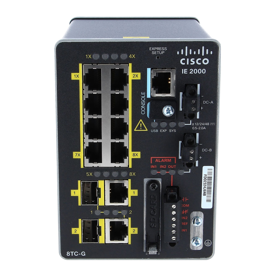
Figure 2 Cisco IE-2000-8TC-L Front Panel View ± 1 2 /2 4 /4 0 .5 -2 .0 A 8 T C 10/100 Ethernet ports (downlink ports) Power connector DC-B Dual-purpose ports (uplink ports) Alarm connector USB mini-Type B (console) port... -
Page 11: 1 Use A Screwdriver To Remove The Port Cover And Access The Port
Figure 3 Cisco IE-2000-16TC-L Front Panel View ± 1 2 /2 4 /4 0 .5 -3 .0 A 1 6 T 10/100 Ethernet ports (downlink ports) Power connector DC-B Dual-purpose ports (uplink ports) Alarm connector USB mini-Type B (console) port... - Page 12 Figure 4 Cisco IE-2000-16PTC-G-E Front Panel View ± 1 2 /2 4 0 .5 -3 /4 8 .0 A P o E S T A T U S P o E IN - IN + 1 6 P T C - 5 4 V , 2 .5...
-
Page 13: Base-T Downlink Ports
In all cases, the attached device must be within 328 feet (100 meters). 100BASE-TX traffic requires CAT5 cable. 10BASE-T traffic can use Category 3 or Category 4 cables. When connecting the switch to workstations, servers, routers, and Cisco IP phones, make sure that the cable is a straight-through cable. -
Page 14: Dual-Purpose Gigabit Ethernet Uplink Ports
Power over Ethernet Ports On certain models of the IE 2000 switch, four of the 10/100BASE-T ports are available as PoE ports. The four ports can operate as PoE (IEEE 802.3af) ports or can be configured to operate as PoE+ (IE 802.at) ports. Each PoE port requires 15.4 Watts of power while PoE+ requires 30 Watts. -
Page 15: Power Connectors
PoE Power Connector The IE 2000 switch models with PoE capability (IE-2000-16PTC-G-E, IE-2000-16PTC-G-L, and IE-2000-16PTC-G-NX) are equipped with an additional DC input terminal block. This DC terminal block allows the connection of a second power... -
Page 16: Alarm Connector
Alarm Connector You connect the alarm signals to the switch through the alarm connector. The switch supports two alarm inputs and one alarm output relay. The alarm connector is on the bottom right of the front panel. See Figure 3 on page The alarm connector provides six alarm wire connections. -
Page 17: Sfp Modules
SFP Modules The switch Ethernet SFP modules provide connections to other devices. These field-replaceable transceiver modules provide the uplink interfaces. LC connectors provide fiber-optic connections; RJ-45 connectors for copper connections. You can use any combination of the supported SFP modules listed in Table 2 on page Table 2 SFP Module Maximum Operating Temperature by Model... -
Page 18: Leds
GLC-ZX-SMD with DOM support For minimum software requirements, refer to the Release Notes for your platform. For an up-to-date list of supported SFP models for Cisco Industrial Ethernet switches, see http://www.cisco.com/en/US/docs/interfaces_modules/transceiver_modules/compatibility/matrix/OL_6981.html#wp1 38176 For installation instructions, see your SFP module documentation and the... -
Page 19: Power Connector Dc-B
Power connector DC-A LED Note: On IE 2000 switches with PoE support, the two SFP ports and the associated LEDs are replaced by a PoE DC-input terminal block and a PoE LED. For more information, see PoE Status LED, page Express Setup LED The Express Setup LED displays the express setup mode for the initial configuration. -
Page 20: System Led
System LED The System LED shows whether the system is receiving power and is functioning properly. Table 4 System LED Color System Status System is not powered on. Blinking green Boot fast is in progress. Green System is operating normally. Switch is not functioning properly. -
Page 21: Power Status Leds
Power Status LEDs The switch can operate with one or two DC power sources. Each DC input has an associated LED that shows the status of the corresponding DC input. If power is present on the circuit, the LED is green. If power is not present, the LED color depends on the alarm configuration. -
Page 22: Poe Status Led
1 6 T Dual-purpose port LEDs PoE Status LED The PoE STATUS LED is located on the front panel of the IE 2000 switch models that are equipped with PoE ports.The LED displays the functionality and status of the PoE ports. -
Page 23: Flash Memory Card
Caution: Non-compliant cabling or powered devices can cause a PoE port fault. Use only standard-compliant cabling to connect Cisco pre-standard IP Phones and wireless access points or IEEE 802.3af-compliant devices. You must remove any cable or device that causes a PoE fault. -
Page 24: Management Options
Cisco IOS CLI The switch CLI is based on Cisco IOS software and is enhanced to support desktop-switching features. You can fully configure and monitor the switch. You can access the CLI either by connecting your management station directly to the switch management port, or a console port, or by using Telnet from a remote management station. -
Page 25: Network Configurations
SNMP application for more information. Common Industrial Protocol The Common Industrial Protocol (CIP) management objects are supported. The Cisco IE 2000 can be managed by CIP-based management tools, allowing the user to manage an entire industrial automation system with one tool. ... -
Page 27: Switch Installation
1001 Warning: Before performing any of the following procedures, ensure that power is removed from the DC circuit. Statement 1003 Warning: Read the installation instructions before you connect the system to its power source. Statement 1004 Cisco Systems, Inc. www.cisco.com... - Page 28 Warning: This unit is intended for installation in restricted access areas. A restricted access area can be accessed only through the use of a special tool, lock and key, or other means of security. Statement 1017 Warning: This equipment must be grounded. Never defeat the ground conductor or operate the equipment in the absence of a suitably installed ground conductor.
-
Page 29: North American Hazardous Location Approval
Warning: When used in a Class I, Division 2, hazardous location, this equipment must be mounted in a suitable enclosure with proper wiring method, for all power, input and output wiring, that complies with the governing electrical codes and in accordance with the authority having jurisdiction over Class I, Division 2 installations. Statement 1066 Warning: Use twisted-pair supply wires suitable for 86°F (30°C) above surrounding ambient temperature outside... -
Page 30: Emc Environmental Conditions For Products Installed In The European Union
Before installation, observe these general guidelines: Caution: Proper ESD protection is required whenever you handle Cisco equipment. Installation and maintenance personnel should be properly grounded by using ground straps to eliminate the risk of ESD damage to the switch. Caution: Do not touch connectors or pins on component boards. -
Page 31: Verifying Package Contents
Connect the unit only to a Class 2 DC power source. Verifying Package Contents The Cisco IE 2000 Switch Getting Started Guide on Cisco.com describes the box contents. If any item is missing or damaged, contact your Cisco representative or reseller for support. - Page 32 Figure 12 Installing the Flash Memory Card in the Switch ± 1 2 /2 4 /4 0 .5 -3 .0 A 1 6 T Figure 13 Removing the Flash Memory Card from the Switch ± 1 2 /2 4 /4 0 .5 -3 .0 A 1 6 T...
-
Page 33: Connecting To A Console Port
After the card is installed, close the guard door and fasten the captive screw using a Phillips screwdriver to keep the door in place. Connecting to a Console Port You can enter Cisco IOS commands and parameters through the CLI. Use one of these options to access the CLI: RJ-45 Console Port, page 33 ... - Page 34 If you are connecting the switch USB-mini console port to a Windows-based PC for the first time, install a USB driver. Installing the Cisco Microsoft Windows XP, 2000, Vista, 7, 8, and 10 USB Device Driver, page 99 for more information.
- Page 35 Remove the cover. Figure 15 Removing the USB Mini-Type B Console Port Cover ± 1 2 /2 4 /4 0 .5 -3 .0 A 1 6 T Connect a USB cable to the PC USB port. Connect the other end of the cable to the switch mini-B (5-pin connector) USB-mini console port. See Figure 16 on page...
- Page 36 Click the Hardware tab and choose Device Manager. Expand the Ports section. The assigned COM port appears in parenthesis at the end of the line with this entry: Cisco USB System Management Console. Start the terminal-emulation program on the PC or the terminal.
-
Page 37: Connecting To Power
— 1 stop bit — No parity — None (flow control) Connect power to the switch as described in Connecting to Power, page When the PC or terminal displays the bootloader sequence, press Enter to display the setup prompt. Follow the steps in the Completing the Setup Program, page 100. -
Page 38: Grounding The Switch
1. The models that support PoE provide up to four ports of either PoE (15.4 W per port; IEEE 802.3af) or PoE+ (30 W per port; IEEE 802.3at), depending on the power source used. See Power Requirements, page Installing the Power Converter on a DIN Rail, Wall, or Rack Adapter You install the power converter on a DIN rail, wall, or rack as you would a switch module. - Page 39 Figure 17 Crimping the Ring Terminal Slide the ground screw through the terminal. Insert the ground screw into the functional ground screw opening on the front panel. Use a ratcheting torque screwdriver to tighten the ground screws and ring terminal to the switch front panel to 3.5 in-lb (0.4 N-m).
- Page 40 Figure 18 Installing the Ground-Lug Screw (Single Ring Terminal) ± 1 2 /2 4 /4 0 .5 -3 .0 A 1 6 T Ground cable...
-
Page 41: Connecting The Power Converter To An Ac Power Source
Figure 19 Installing the Ground-Lug Screws (Two Single Ring Terminals) ± 1 2 /2 4 /4 0 .5 -3 .0 A 1 6 T Ground cable Attach the other end of the ground wire to a grounded bare metal surface, such as a ground bus, a grounded DIN rail, or a grounded bare rack. -
Page 42: Connecting The Power Converter To A Dc Power Source
Connecting the AC Power Source to the Power Converter Caution: AC power sources must be dedicated AC branch circuits. Each branch circuit must be protected by a dedicated two-pole circuit breaker. Caution: Do not turn on AC power until the wiring is secured. Remove the plastic cover from the input power terminals and set it aside. - Page 43 Use copper conductors only, rated at a minimum temperature of 167°F (75°C). Measure a single length of stranded copper wire long enough to connect the power converter to the earth ground. The wire color differs depending on country. For connections from the power converter to earth ground, use shielded 18-AWG stranded copper wire, such as Belden part number 9912 or the equivalent.
-
Page 44: Wiring The Dc Power Source
Figure 21 AC/DC Power Input Terminal Block Wire Connections to a DC Source Earth ground wire connection Positive DC connection Return wire connection (to DC return) Warning: An exposed wire lead from a DC-input power source can conduct harmful levels of electricity. Be sure that no exposed portion of the DC-input power source wire extends from the power and relay connector. - Page 45 Warning: Only trained and qualified personnel should be allowed to install, replace, or service this equipment. Statement 1030 Caution: For wire connections to the power and alarm connectors, you must use UL- and CSA-rated, style 1007 or 1569 twisted-pair copper appliance wiring material (AWM) wire (such as Belden part number 9318). To wire the switch to a DC power source, follow these steps: Locate the two power connectors on the switch front panel labeled DC-A and DC-B (see Figure 22 on page...
- Page 46 Figure 24 Removing the Power Connectors from the Switch ± 1 2 /2 4 /4 0 .5 -3 .0 A 1 6 T Power connectors On the power connector, insert the exposed part of the positive wire into the connection labeled “+” and the exposed part of the return wire into the connection labeled “–”.
- Page 47 Figure 25 Inserting Wires in the Power Connector Power source positive connection Power source return connection Use a ratcheting torque flathead screwdriver to torque the power connector captive screws (above the installed wire leads) to 2 in-lb (0.23 N-m). See Figure 26 on page Note: Do not over-torque the power connector’s captive screws.
- Page 48 Figure 26 Torquing the Power Connector Captive Screws Power connector captive screws Connect the other end of the positive wire to the positive terminal on the DC power source, and connect the other end of the return wire to the return terminal on the DC power source. When you are testing the switch, one power connection is sufficient.
- Page 49 Figure 27 Completed DC Power Connections on the Power Connectors Power source A positive connection Power source B positive connection Power source A return connection Power source B return connection For a –48 VDC power source, this table describes the wiring connections for Figure 27 on page Power source A return connection Power source B return connection...
- Page 50 Figure 28 Attaching the Power Connectors to the Switch ± 1 2 /2 4 /4 0 .5 -3 .0 A 1 6 T DC-A power connector DC-B power connector DC-A power connection DC-B power connection...
- Page 51 This procedure is applicable only to the IE 2000/2000U switch models that are PoE capable. If you have a PoE capable IE 2000 switch and do not plan on using PoE, you do not need to attach power to the PoE DC-input connector; the switch can operate without the connection being made.
- Page 52 Figure 30 PoE-capable Switch with PoE Power Supply Module Connected R -I E 6 5 W -P C 5 4 V -D C -- -, U u tp 1 .2 u t D I E - 2 0 0 0 2 4 V , 2 .1 R tn...
- Page 53 Verify that power is off to the DC circuit that you are going to attach to the switch PoE DC-input connector. This can be either of the two power supplies (AC-input or DC-input) or site source DC. As an added precaution, place the appropriate safety flag and lockout devices at the source power circuit breaker, or place a piece of adhesive tape over the circuit breaker handle to prevent accidental power restoration while you are working on the circuit.
-
Page 54: Applying Power To The Power Converter
Obtaining Documentation and Submitting a Service Request. Note: You can disable the boot fast and run POST by using the Cisco IOS CLI. See the Cisco IE 2000 Switch Software Configuration Guide and the Cisco IE 2000 Switch Command Reference for more information. Disconnecting Power To disconnect power after successfully running boot fast, follow these steps: Turn off power to the switch. -
Page 55: Installing The Switch On A Din Rail
Warning: This equipment is supplied as “open type” equipment. It must be mounted within an enclosure that is suitably designed for those specific environmental conditions that will be present and appropriately designed to prevent personal injury resulting from accessibility to live parts. The interior of the enclosure must be accessible only by the use of a tool. -
Page 56: Removing The Switch From A Din Rail
Figure 31 Position the Hooks Over the DIN Rail DIN Rail Switch Push the switch toward the DIN rail to cause the spring-loaded latch at the bottom rear of the switch to move down, and snap into place. After the switch is mounted on the DIN rail, connect the power and alarm wires, as described in the Connecting Alarm Circuits, page For configuration instructions about the CLI setup program, see the... -
Page 57: Wiring The External Alarms
Figure 32 Releasing the Spring-Loaded Latch from the DIN Rail Push latch down Remove the switch from the DIN rail. Connecting Alarm Circuits After the switch is installed, you are ready to connect the DC power and alarm connections. Wiring the Protective Ground and DC Power for Alarm Circuits, page 57 ... - Page 58 Alarm signals are connected to the switch through the six-pin alarm connector. Three connections are dedicated to the two alarm input circuits: alarm input 1, alarm input 2, and a reference ground. An alarm input and the reference ground wiring connection are required to complete a single alarm input circuit. The three remaining connections are for the alarm output circuit: a normally open output, a normally closed output, and a common signal.
- Page 59 Figure 33 Removing the Alarm Connector ± 1 2 /2 4 /4 0 .5 -3 .0 A 1 6 T Alarm connector Measure two strands of twisted-pair wire (18-to-20 AWG) long enough to connect to the external alarm device. You can choose between setting up an external alarm input or output circuit. Use a wire stripper to remove the casing from both ends of each wire to 0.25 inch (6.3 mm) ±...
- Page 60 Figure 34 Inserting Wires into the Alarm Connector (Alarm Input Circuit) IN1 - External device connection 1 REF - External device connection 2 Use a ratcheting torque flathead screwdriver to tighten the alarm connector captive screw (above the installed wire leads) to 2 in-lb (0.23 N-m).
- Page 61 Figure 36 Completed Connections for Three External Alarm Devices on the Alarm Connector IN1 wired connection COM wired connection REF wired connection NO wired connection Attaching the Alarm Connector to the Switch Warning: Failure to securely tighten the captive screws can result in an electrical arc if the connector is accidentally removed.
-
Page 62: Connecting Destination Ports
Figure 37 Connecting the Alarm Connector to the Switch ± 1 2 /2 4 /4 0 .5 -3 .0 A 1 6 T Alarm connector upper captive screw Use a ratcheting torque flathead screwdriver to tighten the captive screws on the sides of the alarm connector. Connecting Destination Ports These section provide more information about connecting to the destination ports: ... - Page 63 When connecting to 1000BASE-T-compatible devices, use a twisted four-pair, CAT5 or higher cable. The auto-MDIX feature is enabled by default. For configuration information for this feature, see the Cisco IE 2000 Switch Software Configuration Guide or the Cisco IE 2000 Switch Command Reference.
-
Page 64: Installing And Removing Sfp Modules
The port LED is amber while Spanning Tree Protocol (STP) discovers the topology and searches for loops. This can take up to 30 seconds, and then the port LED turns green. If the port LED does not turn on: — The device at the other end might not be turned on. - Page 65 Figure 39 LC SFP Module with Open Bale-Clasp Latch Figure 40 Installing an SFP Module into an SFP Module Slot ± 1 2 /2 4 /4 0 .5 -3 .0 A 1 6 T Installing LC SFP Modules To insert an LC SFP module into the SFP module slot: Attach an ESD-preventive wrist strap to your wrist and to a grounded bare metal surface.
- Page 66 Position the SFP transceiver in front of the port socket opening. Note: Different Cisco devices have different SFP transceiver socket configurations. Your Cisco device might require that the SFP transceiver be installed with the bale-clasp either in a latch-up or a latch-down orientation. Verify that the SFP transceiver is oriented correctly when you position it in front of the port socket.
-
Page 67: Removing Sfp Modules From Sfp Module Slots
— Amber indicates that the port is discovering the network topology and searching for loops. This process takes about 30 seconds, and then the LED turns green. — Off indicates that the target device might not be turned on, there might be a cable problem, or there might be a problem with the adapter installed in the target device. -
Page 68: Connecting To Sfp Modules
Connecting to SFP Modules This section describes how to connect to a fiber-optic or copper SFP port. To connect to an RJ-45 Gigabit Ethernet port, Connecting to a Dual-Purpose Port, page 70. For instructions on how to install or remove an SFP module, see Installing and Removing SFP Modules, page Warning: Class 1 laser product. - Page 69 Figure 43 Connecting to a Fiber-Optic SFP Module Port ± 1 2 /2 4 /4 0 .5 -3 .0 A 1 6 T LC connector Insert the other cable end into a fiber-optic receptacle on a target device. Observe the port status LED: —...
- Page 70 — The LED turns amber while the STP discovers the network topology and searches for loops. This process takes about 30 seconds, and then the port LED turns green. — If the LED is off, the target device might not be turned on, there might be a cable problem, or there might be problem with the adapter installed in the target device.
-
Page 71: Verifying Switch Operation
You can change this setting and configure the port to recognize only an RJ-45 connector or only an SFP module by using the media type interface configuration command. For more information, see the Cisco IE 2000 Switch Command Reference. - Page 72 Use the CLI to configure the switch as an individual switch from the console. See the Command Reference on Cisco.com for information about using the CLI. Start an SNMP application such as the CiscoView application. Start the Common Industrial Protocol (CIP) management tool. You can manage an entire industrial automation system...
-
Page 73: Troubleshooting
Note: You can disable the boot fast and run POST by using the Cisco IOS CLI, see the Cisco IE 2000 Switch Software Configuration Guide and the Cisco IE 2000 Switch Command Reference for more information. Switch LEDs Look at the port LEDs information when troubleshooting the switch. -
Page 74: Link Status
Verify the cable type. See Cable and Connectors, page SFP Module Use only Cisco SFP modules. Each Cisco module has an internal serial EEPROM that is encoded with security information. This encoding verifies that the module meets the requirements for the switch. ... -
Page 75: Interface Settings
You can enable UniDirectional Link Detection (UDLD) on the switch to help identify unidirectional link problems. For information about enabling UDLD on the switch, see the “Understanding UDLD” section in the switch software configuration guide on Cisco.com. Switch Performance Speed, Duplex, and Autonegotiation Port statistics that show a large amount of alignment errors, frame check sequence (FCS), or late-collisions errors, might mean a speed or duplex mismatch. -
Page 76: Cabling Distance
Finding the Switch Serial Number If you contact Cisco Technical Assistance, you need to know the serial number of your switch. The serial number is on the compliance label on the right-hand side of the switch. See Figure 45 on page 77. - Page 77 Figure 45 Serial Number Location for the Cisco IE-2000 Switches SN: XXXNNNNXXXX...
- Page 79 = linear feet per minute. The safety certifications apply only to ambient temperatures under 140°F (60°C). However, the Cisco IE 2000 switch can function in the substation and traffic signal installations under the environmental conditions shown in Table 14 on page...
- Page 80 54 VDC at 1.2 A. The IE 2000 switch models with PoE capability are equipped with an additional DC input terminal block that allows the connection of a second power supply or a second input from site source DC power to operate the PoE ports. The PoE terminal block accepts 48 VDC or 54 VDC at up to 2.5 A, depending on the amount of power that is provided to the connected...
- Page 81 Table 15 Cisco IE 2000 Series Technical Specifications (continued) Power consumption 10-port models—12.5 W (typical), 17 W (maximum) (continued) Cisco IE-2000-8TC-L Cisco IE-2000-8TC-B Cisco IE-2000-8TC-G-L Cisco IE-2000-8TC-G-B Cisco IE-2000-8TC-G-N 10-port models—15 W (typical), 20 W (maximum) ...
- Page 82 Table 15 Cisco IE 2000 Series Technical Specifications (continued) Weight (continued) 10-port models—2.75 lbs (1.25 kg) Cisco IE-2000-8TC-L Cisco IE-2000-8TC-B Cisco IE-2000-8TC-G-L Cisco IE-2000-8TC-G-B Cisco IE-2000-8TC-G-N 10-port models—3.45 lbs (1.57 kg) Cisco IE-2000-8TC-G-E 18- and 20-port models: 4.35 lbs (1.98 kg) ...
-
Page 83: Alarm Ratings
2. The maximum operating temperature of the switch varies depending on the type of SFP module that you use. Alarm Ratings Table 16 on page 83 lists the alarm ratings for the Cisco IE 2000 switches. Table 16 Alarm Input and Output Ratings... - Page 84 Hazardous Locations Standards Table 17 on page 84 lists the hazardous location standards for the Cisco IE 2000 switches. Table 17 Hazardous Locations Standards The following standards were used for the hazardous Les normes suivantes ont été appliquées pour les...
-
Page 85: Connector Specifications
Figure 46 10/100 Port Pinouts Label 4 5 6 7 8 For the three models of IE 2000 switch that support PoE, connector pins 4 and 5 supply +48 VDC and pins 7 and 8 are the DC voltage return lines. Cisco Systems, Inc. -
Page 86: Sfp Module Connectors
SFP Module Connectors Figure 47 on page 86 shows the MT-RJ SFP module fiber-optic local connector (LC). Figure 47 Fiber-Optic SFP Module LC Connector Warning: Invisible laser radiation may be emitted from disconnected fibers or connectors. Do not stare into beams or view directly with optical instruments. -
Page 87: Console Port
Console Port The switch has two console ports: a USB 5-pin mini-Type B port on the front panel (see Figure 50 on page 87) and an RJ-45 console port on the rear panel. Figure 50 USB Mini-Type B Port The USB console port uses a USB Type A to 5-pin mini-Type B cable, shown in Figure 51 on page 87. -
Page 88: Cables And Adapters
Cables and Adapters SFP Module Cables, page 88 Cable Pinouts, page 91 Console Port Adapter Pinouts, page 92 SFP Module Cables Each port must match the wave-length specifications on each end of the cable, and for reliable communications, the cable must not exceed the allowable length. - Page 89 Table 19 Industrial and Rugged SFPs—Fiber-Optic SFP Module Port Cabling Specifications (continued) Type of SFP Model Wavelength Fiber Core Modal Cable Distance Module (nanometers) Type Size/Claddin Bandwidth g Size (MHz/km) (micron) 100BASE-FX GLC-FE-100FX-RGD 1310 62.5/125 1.24 miles (2 km) 62.5/125 50/125 50/125 100BASE-LX10...
- Page 90 1560.61 1000BASE-T GLC-T — — — 328 ft. (100 m) View the CWDM data sheet at http://www.cisco.com/en/US/prod/collateral/modules/ps5455/ps6575/product_data_sheet09186a00801a557c_ps49 99_Products_Data_Sheet.html View the DWDM data sheet at http://www.cisco.com/en/US/prod/collateral/modules/ps5455/ps6576/product_data_sheet0900aecd80582763.html Table 21 Extended Temperature SFPs—Fiber-Optic SFP Module Port Cabling Specifications Type of SFP Module Model...
-
Page 91: Cable Pinouts
Table 21 Extended Temperature SFPs—Fiber-Optic SFP Module Port Cabling Specifications (continued) Type of SFP Module Model Wavelength Fiber Core Size/ Modal Cable Distance (nanometers) Type Cladding Bandwidth Size (MHz/km) (micron) 1000BASE-SX SFP-GE-S 62.5 722 feet (220 m) 62.5 902 feet (275 m) 50.0 1640 feet (500 m) 50.0... -
Page 92: Console Port Adapter Pinouts
Figure 54 Four Twisted-Pair Straight-Through Cable Schematic for 1000BASE-T Ports Switch Router or PC 1 TP0+ 1 TP0+ 2 TP0- 2 TP0- 3 TP1+ 3 TP1+ 6 TP1- 6 TP1- 4 TP2+ 4 TP2+ 5 TP2- 5 TP2- 7 TP3+ 7 TP3+ 8 TP3- 8 TP3-... - Page 93 RJ-45-to-DB-25 female DTE adapter, and the console device. Note: The RJ-45-to-DB-25 female DTE adapter is not supplied with the switch. You can order this adapter from Cisco (part number ACS-DSBUASYN=). Table 23...
-
Page 95: Accessing The Cli Through The Console Port
For installation procedures, see Switch Installation, page 27 Accessing the CLI Through the Console Port You can enter Cisco IOS commands and parameters through the CLI. Use one of these options to access the CLI: RJ-45 Console Port, page 96 ... - Page 96 Figure 57 Removing the USB Mini-Type B Console Port Cover ± 1 2 /2 4 /4 0 .5 -3 .0 A 1 6 T RJ-45 Console Port Connect the RJ-45-to-DB-9 adapter cable to the 9-pin serial port on the PC. Connect the other end of the cable to the switch console port.
- Page 97 If you are connecting the switch USB-mini console port to a Windows-based PC for the first time, install a USB driver. Installing the Cisco Microsoft Windows XP, 2000, Vista, 7, 8, and 10 USB Device Driver, page 99 for more...
- Page 98 Click the Hardware tab and choose Device Manager. Expand the Ports section. The assigned COM port appears in parenthesis at the end of the line with this entry: Cisco USB System Management Console. Start the terminal-emulation program on the PC or the terminal.
- Page 99 Completing the Setup Program, page 100. Installing the Cisco Microsoft Windows XP, 2000, Vista, 7, 8, and 10 USB Device Driver A USB device driver must be installed the first time a Microsoft Windows-based PC is connected to the USB console port on the switch.
-
Page 100: Entering The Initial Configuration Information
Assign an IP address and any other configuration information necessary for the switch to communicate with the local routers and the Internet. This information is also required if you plan to use Device Manager or Cisco Network Assistant to configure and manage the switch. - Page 101 If you enter N, the switch appears as a candidate switch in the Cisco Network Assistant GUI. You can configure the switch as a command switch later through the CLI, Device Manager, or the Cisco Network Assistant application.
- Page 102 > prompt through the console port by using a terminal emulation program or through the network by using Telnet. For configuration information, see the switch Cisco IE 2000 Switch Software Configuration Guide or the Cisco IE 2000 Switch Command Reference.
Need help?
Do you have a question about the IE 2000 and is the answer not in the manual?
Questions and answers