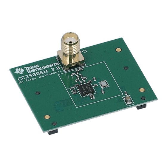
Texas Instruments CC2500 TK Manual

Texas Instruments CC2500 TK Manual

Low-cost low-power 2.4 ghz rf transceiver
Table of Contents

Advertisement

Quick Links

CC2500
Low-Cost Low-Power 2.4 GHz RF Transceiver

Applications

 2400-2483.5 MHz ISM/SRD band systems
 Consumer electronics
 Wireless game controllers

Product Description

The CC2500 is a low-cost 2.4 GHz transceiver
designed for very low-power wireless appli-
cations. The circuit is intended for the 2400-
2483.5 MHz ISM (Industrial, Scientific and
Medical) and SRD (Short Range Device)
frequency band.
The RF transceiver is integrated with a highly
configurable baseband modem. The modem
supports various modulation formats and has
a configurable data rate up to 500 kBaud.
CC2500 provides extensive hardware support
for packet handling, data buffering, burst
transmissions, clear channel assessment, link
quality indication, and wake-on-radio.
The main operating parameters and the 64-
byte transmit/receive FIFOs of CC2500 can be

Key Features

RF Performance

High sensitivity (–104 dBm at 2.4 kBaud,
1% packet error rate)
Low current consumption (13.3 mA in RX,
250 kBaud, input well above sensitivity
limit)
Programmable output power up to +1 dBm
Excellent receiver selectivity and blocking
performance
Programmable data rate from 1.2 to 500
kBaud
Frequency range: 2400 – 2483.5 MHz

Analog Features

OOK, 2-FSK, GFSK, and MSK supported
Suitable for frequency hopping and multi-
channel systems due to a fast settling
 Wireless audio
 Wireless keyboard and mouse
 RF enabled remote controls
controlled via an SPI interface. In a typical
system, the CC2500 will be used together with
a microcontroller and a few additional passive
components.
frequency synthesizer with 90 us settling
time
Automatic
(AFC) can be used to align the frequency
synthesizer
frequency
Integrated analog temperature sensor

Digital Features

Flexible
systems: On-chip support for sync word
detection, address check, flexible packet
length, and automatic CRC handling
Efficient SPI interface: All registers can be
programmed with one "burst" transfer
Digital RSSI output
Programmable channel filter bandwidth
Programmable
indicator
SWRS040C
CC2500
Frequency
Compensation
to
the
received
support
for
packet
Carrier
Sense
Page 1 of 89
centre
oriented
(CS)

Advertisement

Table of Contents
loading
Need help?

Need help?

Do you have a question about the CC2500 TK and is the answer not in the manual?

Questions and answers

Subscribe to Our Youtube Channel

Summary of Contents for Texas Instruments CC2500 TK

  • Page 1: Applications

    CC2500 CC2500 Low-Cost Low-Power 2.4 GHz RF Transceiver Applications  2400-2483.5 MHz ISM/SRD band systems  Wireless audio  Consumer electronics  Wireless keyboard and mouse  Wireless game controllers  RF enabled remote controls Product Description The CC2500 is a low-cost 2.4 GHz transceiver controlled via an SPI interface.
  • Page 2: Low-Power Features

    CC2500  Programmable Preamble Quality Indicator General (PQI) for improved protection against false  Few external components: Complete on- sync word detection in random noise chip frequency synthesizer, no external  Support for automatic Clear Channel filters or RF switch needed Assessment (CCA) before transmitting (for ...
  • Page 3: Abbreviations

    CC2500 Abbreviations Abbreviations used in this data sheet are described below. Adjacent Channel Power Most Significant Bit Analog to Digital Converter Minimum Shift Keying Automatic Frequency Offset Compensation Not Applicable Automatic Gain Control Non Return to Zero (Coding) Automatic Meter Reading On Off Keying ARIB Association of Radio Industries and Businesses...
  • Page 4: Table Of Contents

    CC2500 Table of Contents APPLICATIONS ............................1 PRODUCT DESCRIPTION.........................1 KEY FEATURES ............................1 RF P ............................1 ERFORMANCE ............................1 NALOG EATURES ............................1 IGITAL EATURES ...........................2 OWER EATURES ................................2 ENERAL ABBREVIATIONS............................3 TABLE OF CONTENTS ..........................4 ......................6 BSOLUTE AXIMUM ATINGS ........................6 PERATING ONDITIONS .......................6 ENERAL HARACTERISTICS .......................7 LECTRICAL...
  • Page 5 CC2500 16.3 .........................34 MPLITUDE ODULATION ...........34 ECEIVED IGNAL UALIFIERS AND UALITY NFORMATION 17.1 ........................34 UALIFIER 17.2 (PQT) ...................34 REAMBLE UALITY HRESHOLD 17.3 RSSI..............................34 17.4 (CS)..........................35 ARRIER ENSE 17.5 (CCA) ....................37 LEAR HANNEL SSESSMENT 17.6 (LQI) .......................37 UALITY NDICATOR ................37 ORWARD RROR ORRECTION WITH NTERLEAVING...
  • Page 6: Absolute Maximum Ratings

    CC2500 Absolute Maximum Ratings Under no circumstances must the absolute maximum ratings given in Table 1 be violated. Stress exceeding one or more of the limiting values may cause permanent damage to the device. Caution! sensitive device. Precaution should be used when handling the device in order to prevent permanent damage.
  • Page 7: Electrical Specifications

    CC2500 Electrical Specifications Current Consumption Tc = 25C, VDD = 3.0 V if nothing else stated. All measurement results obtained using the CC2500EM reference design ([4]). Parameter Unit Condition/Note Current consumption in Voltage regulator to digital part off, register values retained power down modes (SLEEP state).
  • Page 8 CC2500 Current consumption, 11.1 Transmit mode, –12 dBm output power TX states 15.0 Transmit mode, -6 dBm output power 21.2 Transmit mode, 0 dBm output power 21.5 Transmit mode, +1 dBm output power Table 4: Current Consumption SWRS040C Page 8 of 89...
  • Page 9: Rf Receive Section

    CC2500 RF Receive Section Tc = 25C, VDD = 3.0 V if nothing else stated. All measurement results obtained using the CC2500EM reference design ([4]). Parameter Unit Condition/Note Digital channel filter User programmable. The bandwidth limits are bandwidth proportional to crystal frequency (given values assume a 26.0 MHz crystal).
  • Page 10 CC2500 Parameter Unit Condition/Note 250 kBaud data rate, sensitivity optimized, MDMCFG2.DEM_DCFILT_OFF=0 (MSK, 1% packet error rate, 20 bytes packet length, 540 kHz digital channel filter bandwidth) Receiver sensitivity –89 Saturation –13 Adjacent channel rejection Desired channel 3 dB above the sensitivity limit. 750 kHz channel spacing Alternate channel rejection Desired channel 3 dB above the sensitivity limit.
  • Page 11: Rf Transmit Section

    CC2500 RF Transmit Section Tc = 25C, VDD = 3.0 V, 0 dBm if nothing else stated. All measurement results obtained using the CC2500EM reference design ([4]). Parameter Unit Condition/Note  Differential load 80 + j74 Differential impedance as seen from the RF-port (RF_P and impedance RF_N) towards the antenna.
  • Page 12: Crystal Oscillator

    CC2500 Crystal Oscillator Tc = 25C, VDD = 3.0 V if nothing else stated. Parameter Unit Condition/Note Crystal frequency Tolerance ±40 This is the total tolerance including a) initial tolerance, b) crystal loading, c) aging, and d) temperature dependence. The acceptable crystal tolerance depends on RF frequency and channel spacing / bandwidth.
  • Page 13: Frequency Synthesizer Characteristics

    CC2500 Frequency Synthesizer Characteristics Tc = 25C, VDD = 3.0 V if nothing else stated. All measurement results obtained using the CC2500EM reference design ([4]). Min figures are given using a 27 MHz crystal. Typ and max figures are given using a 26 MHz crystal. Parameter Unit Condition/Note...
  • Page 14: Analog Temperature Sensor

    CC2500 Analog Temperature Sensor The characteristics of the analog temperature sensor at 3.0 V supply voltage are listed in Table 10 below. Note that it is necessary to write 0xBF to the PTEST register to use the analog temperature sensor in the IDLE state. Parameter Unit Condition/Note...
  • Page 15: Pin Configuration

    CC2500 Pin Configuration 20 19 18 17 16 SCLK AVDD SO (GDO1) AVDD GDO2 RF_N DVDD RF_P DCOUPL AVDD Exposed die attach pad Figure 1: Pinout Top View Note: The exposed die attach pad must be connected to a solid ground plane as this is the main ground connection for the chip.
  • Page 16 CC2500 Pin # Pin Name Pin Type Description SCLK Digital Input Serial configuration interface, clock input Digital Output Serial configuration interface, data output. SO (GDO1) Optional general output pin when CSn is high GDO2 Digital Output Digital output pin for general use: ...
  • Page 17: Circuit Description

    CC2500 Circuit Description RADIO CONTROL SCLK SO (GDO1) RF_P FREQ RF_N SYNTH GDO0 (ATEST) GDO2 RC OSC BIAS XOSC RBIAS XOSC_Q1 XOSC_Q2 Figure 2: CC2500 Simplified Block Diagram A simplified block diagram of CC2500 is shown signals to the down-conversion mixers in receive mode.
  • Page 18 CC2500 balun that converts the differential RF signal Crystal on CC2500 to a single-ended RF signal. C121 The crystal oscillator uses an external crystal and C131 are needed for DC blocking. with two loading capacitors (C81 and C101). Together with an appropriate LC network, the See Section 26 on page 50 for details.
  • Page 19: Configuration Overview

    CC2500 Component Value Manufacturer 100 nF ±10%, 0402 X5R Murata GRM15 series 27 pF ±5%, 0402 NP0 Murata GRM15 series C101 27 pF ±5%, 0402 NP0 Murata GRM15 series C121 100 pF ±5%, 0402 NP0 Murata GRM15 series C122 1.0 pF ±0.25 pF, 0402 NP0 Murata GRM15 series C123 1.8 pF ±0.25 pF, 0402 NP0...
  • Page 20: Configuration Software

    CC2500 Lowest power mode. Most register values are retained. Typ. current consumption Sleep 400nA, or 900nA when SPWD or wake-on-radio (WOR) SIDLE wake-on-radio (WOR) is enabled. Default state when the radio is not receiving or transmitting. Typ. CSn=0 current consumption: 1.5mA. Idle SXOFF SCAL...
  • Page 21: 10 4-Wire Serial Configuration And Data Interface

    CC2500  Figure 6: SmartRF Studio [5] User Interface 10 4-wire Serial Configuration and Data Interface CC2500 is configured via a simple 4-wire SPI- transfer of a header byte or during read/write from/to a register, the transfer will be compatible interface (SI, SO, SCLK and CSn) where CC2500 is the slave.
  • Page 22: Chip Status Byte

    CC2500 Figure 7: Configuration Register Write and Read Operations Parameter Description Units SCLK frequency SCLK 100 ns delay inserted between address byte and data byte (single access), or between address and data, and between each data byte (burst access). SCLK frequency, single access No delay between address and data byte SCLK frequency, burst access No delay between address and data byte, or between data bytes...
  • Page 23: Register Access

    CC2500 configuration should only be updated when the reading from FIFO. write chip is in this state. The RX state will be active operations (the R/W bit in the header byte is when the chip is in receive mode. Likewise, TX set to 0), the FIFO_BYTES_AVAILABLE field is active when the chip is transmitting.
  • Page 24: Command Strobes

    CC2500 The TX FIFO is write-only, while the RX FIFO by the radio hardware (e.g. MARCSTATE or is read-only. TXBYTES), there is a small, but finite, probability that a single read from the register The burst bit is used to determine if the FIFO being corrupt.
  • Page 25: Microcontroller Interface And Pin Configuration

    CC2500  access is a write access (R/W=0) or a read When using OOK modulation the first two access (R/W=1). entries into this table are used (index 0 and index 1). If one byte is written to the PATABLE and this value is to be read out then CSn must be set high before the read access in order to set the Since the PATABLE is an 8-byte table, the...
  • Page 26: Optional Radio Control Feature

    CC2500 State changes are commanded as follows: The GDO0 pin can also be used for an on-chip analog temperature sensor. By measuring the When CSn is high the SI and SCLK is set to the desired state according to Table 18. When voltage on the GDO0 pin with an external ADC, CSn goes low the state of SI and SCLK is temperature...
  • Page 27: Receiver Channel Filter Bandwidth

    CC2500 13 Receiver Channel Filter Bandwidth In order to meet different channel width kHz, which is 480 kHz. Assuming 2.44 GHz requirements, the receiver channel filter is frequency and ±20 ppm frequency uncertainty programmable. The MDMCFG4.CHANBW_E and for both the transmitting device and the receiving device, total...
  • Page 28: Byte Synchronization

    CC2500 14.3 Byte Synchronization correlation threshold can be set to 15/16, 16/16, or 30/32 bits match. The sync word can Byte synchronization achieved be further qualified using the preamble quality continuous sync word search. The sync word indicator mechanism described below and/or a is a 16 bit configurable field (can be repeated carrier sense condition.
  • Page 29: Data Whitening

    CC2500 15.1 Data Whitening automatically setting PKTCTRL0.WHITE_DATA=1. All data, except From a radio perspective, the ideal over the air the preamble and the sync word, are then data are random and DC free. This results in XOR-ed with a 9-bit pseudo-random (PN9) the smoothest power distribution over the sequence before being transmitted as shown occupied bandwidth.
  • Page 30 CC2500 to the CC2500 preamble pattern alternating Errata Notes [1] for more sequence of ones and zeros (101010101…). details. The minimum length of the preamble is Note that minimum packet length programmable. When enabling supported (excluding the optional length byte modulator will start transmitting the preamble.
  • Page 31: Packet Filtering In Receive Mode

    CC2500   Pre-program register Set PKTCTRL0.LENGTH_CONFIG=0. PKTLEN mod(600,256)=88.  The transmission ends when the packet  Transmit at least 345 bytes, for example counter reaches 88. A total of 600 bytes by filling the 64-byte TX FIFO six times are transmitted.
  • Page 32: Packet Handling In Transmit Mode

    CC2500 options. Refer also to the CC2500 Errata Notes The modulator will first send the programmed number of preamble bytes. If data is available [1]. in the TX FIFO, the modulator will send the two-byte (optionally 4-byte) sync word and 15.4.1 PKTCTRL0.CC2400_EN=0 then the payload in the TX FIFO.
  • Page 33: Packet Handling In Firmware

    CC2500 bytes that contain CRC status, link quality information on how many bytes are in the RX indication and RSSI value. FIFO and TX FIFO respectively. See Table 33. b) SPI polling 15.7 Packet Handling in Firmware The PKTSTATUS register can be polled at a When implementing a packet oriented radio given rate to get information about the current protocol in firmware, the MCU needs to know...
  • Page 34: Amplitude Modulation

    CC2500 The fraction of a symbol period used to 16.3 Amplitude Modulation change the phase can be modified with the The supported amplitude modulation On-Off setting. This DEVIATN.DEVIATION_M Keying (OOK) simply turns on or off the PA to equivalent to changing the shaping of the modulate 1 and 0 respectively.
  • Page 35: Carrier Sense (Cs)

    CC2500 automatically added to the first byte appended Table 25 provides typical values for the after the data payload. RSSI_offset. The RSSI value read from the RSSI status Figure 13 shows typical plots of RSSI readings register is a 2’s complement number. The as a function of input power level for different following procedure can be used to convert the data rates.
  • Page 36 CC2500 IOCFGx.GDOx_CFG=14 and in the status MAX_DVGA_GAIN[1:0] register bit PKTSTATUS.CS. Other uses of Carrier Sense include the TX-if- -81.5 CCA function (see Section 17.5 on page 37) -90.5 -78.5 and the optional fast RX termination (see Section 19.7 on page 43). -93.5 CS can be used to avoid interference from e.g.
  • Page 37: Clear Channel Assessment (Cca)

    CC2500  17.5 Clear Channel Assessment (CCA) Unless currently receiving a packet  The Clear Channel Assessment CCA) is used Both the above (RSSI below threshold and to indicate if the current channel is free or not currently receiving a packet) busy.
  • Page 38 CC2500 interference and time-varying signal strengths. When FEC and interleaving is used at least In order to increase the robustness to errors extra byte required trellis spanning multiple bits, interleaving is used termination. In addition, the amount of data when FEC is enabled. After de-interleaving, a transmitted over the air must be a multiple of continuous span of errors in the received the size of the interleaver buffer (two bytes).
  • Page 39: Radio Control

    CC2500 19 Radio Control SIDLE SPWD | SWOR SLEEP CAL_ COMPLETE MANCAL IDLE CSn = 0 | WOR 3,4,5 SXOFF SCAL CSn = 0 XOFF SRX | STX | SFSTXON | WOR FS_ WAKEUP FS_ AUTOCAL= 01 & SRX | STX | SFSTXON | WOR FS_ AUTOCAL= 00 | 10 | 11 &...
  • Page 40: Crystal Control

    CC2500 19.1.1 Automatic POR XOSC and voltage regulator switched on A power-on reset circuit is included in the 40 us CC2500 . The minimum requirements stated in Section 4.9 must be followed for the power-on reset to function properly. The internal power- up sequence is completed when CHIP_RDYn goes low.
  • Page 41: Active Modes

    CC2500 oscillator and make the chip enter the IDLE has been successfully transmitted. Then the state. state will change indicated MCSM1.TXOFF_MODE setting. The possible When wake on radio is enabled, the WOR destinations are the same as for RX. module will control the voltage regulator as described in Section 19.5.
  • Page 42: Timing

    CC2500 Event 1 follows Event 0 after a programmed clock. When the chip goes to the SLEEP state, timeout. the RC oscillator will use the last valid calibration result. The frequency of the RC The time between two consecutive Event 0 is oscillator is locked to the main crystal programmed with a mantissa value given by frequency divided by 750.
  • Page 43: Rx Termination Timer

    CC2500 19.7 RX Termination Timer For OOK modulation, lack of carrier sense is only considered valid after eight symbol CC2500 has optional functions for automatic periods. Thus, the MCSM2.RX_TIME_RSSI termination of RX after a programmable time. function can be used in OOK mode when the The main use for this functionality is wake-on- distance between “1”...
  • Page 44: Frequency Programming

    CC2500 Read RXBYTES.NUM_RXBYTES repeatedly at a rate guaranteed to be at FIFO_THR Bytes in TX FIFO Bytes in RX FIFO least twice that of which RF bytes are 0 (0000) received until the same value is returned 1 (0001) twice; store value in 2 (0010) 2.
  • Page 45: Vco

    CC2500 be set to the centre of the lowest channel CHANNR.CHAN, which is multiplied by the frequency that is to be used. channel offset. The resultant carrier frequency is given by: The desired channel number is programmed with the 8-bit channel number register, ...
  • Page 46: Voltage Regulators

    CC2500 23 Voltage Regulators CC2500 contains several on-chip linear voltage If the chip is programmed to enter power-down mode, (SPWD strobe issued), the power will be regulators, which generate the supply voltage needed low-voltage modules. These turned off after CSn goes high. The power and voltage regulators are invisible to the user, and crystal oscillator will be turned on again when can be viewed as integral parts of the various...
  • Page 47 CC2500 Figure 21: PA_POWER and PATABLE Output power, Current consumption, Default power setting typical [dBm] typical [mA] 0xC6 11.1 Table 30: Output Power and Current Consumption for Default PATABLE Setting Output Power, PATABLE Current Consumption, Typical, +25°C, 3.0 V [dBm] Value Typical [mA] (–55 or less)
  • Page 48: Selectivity

    CC2500 25 Selectivity Figure 22 to Figure 26 show the typical selectivity performance (adjacent and alternate rejection). -0.8 -0.6 -0.4 -0.2 Frequency offset [MHz] Figure 22: Typical Selectivity at 2.4 kBaud. IF Frequency is 273.9 kHz. MDMCFG2.DEM_DCFILT_OFF=1 -0.8 -0.6 -0.4 -0.2 Fre que ncy offse t [M Hz] Figure 23: Typical Selectivity at 10 kBaud.
  • Page 49 CC2500 Frequency offset [MHz] Figure 24: Typical Selectivity at 250 kBaud. IF Frequency is 177.7 kHz. MDMCFG2.DEM_DCFILT_OFF=0 Frequency offset [MHz] Figure 25: Typical Selectivity at 250 kBaud. IF Frequency is 457 kHz. MDMCFG2.DEM_DCFILT_OFF=1 Frequency offse t [MHz] Figure 26: Typical Selectivity at 500 kBaud. IF Frequency is 304.7 kHz. MDMCFG2.DEM_DCFILT_OFF=0 SWRS040C Page 49 of 89...
  • Page 50: Crystal Oscillator

    CC2500 26 Crystal Oscillator A crystal in the frequency range 26-27 MHz The crystal oscillator circuit is shown in Figure must be connected between the XOSC_Q1 and 27. Typical component values for different values of C are given in Table 32. XOSC_Q2 pins.
  • Page 51: Pcb Layout Recommendations

    CC2500 = 80 + j74 Ω follow the CC2500EM reference designs [4] as closely as possible. Gerber files for the To ensure optimal matching of the CC2500 reference designs are available for download differential output it is highly recommended to from the TI website.
  • Page 52: General Purpose / Test Output Control Pins

    CC2500 29 General Purpose / Test Output Control Pins The three digital output pins GDO0, GDO1 and IOCFG0.GDO0_CFG register. The voltage on GDO2 are general control pins configured with then proportional GDO0 IOCFG0.GDO0_CFG, IOCFG1.GDO1_CFG temperature. See Section 4.7 on page 14 for and IOCFG2.GDO2_CFG respectively.
  • Page 53 CC2500 GDOx _CFG[5:0]] Description Associated to the RX FIFO: Asserts when RX FIFO is filled at or above the RX FIFO threshold. De-asserts when RX 0 (0x00) FIFO is drained below the same threshold. Associated to the RX FIFO: Asserts when RX FIFO is filled at or above the RX FIFO threshold or the end of packet is 1 (0x01) reached.
  • Page 54: Asynchronous And Synchronous Serial Operation

    CC2500 30 Asynchronous and Synchronous Serial Operation Several features and modes of operation have 30.2 Synchronous Serial Operation been included in the CC2500 to provide Setting PKTCTRL0.PKT_FORMAT backward compatibility with previous Chipcon enables synchronous serial mode. In the products and other existing RF communication synchronous serial mode, data is transferred systems.
  • Page 55: Frequency Hopping And Multi-Channel Systems

    CC2500 31.2 Frequency Hopping and Multi- time is reduced from approximately 720 µs to Channel Systems approximately 150 µs. The blanking interval between each frequency then The 2.400 – 2.4835 GHz band is shared by approximately 240 us many systems both in industrial, office and home environments.
  • Page 56: Crystal Drift Compensation

    CC2500 31.6 Crystal Drift Compensation 3. The CC25XX Folded Dipole reference design [8] contains schematics and layout files The CC2500 has a very fine frequency for a CC2500EM with a folded dipole PCB resolution (see Table 9). This feature can be antenna.
  • Page 57: Configuration Registers

    CC2500 32 Configuration Registers The configuration of CC2500 is done by There are also 12 status registers, which are listed in Table 36. These registers, which are programming 8-bit registers. The optimum read-only, contain information about the status configuration data based on selected system of CC2500 .
  • Page 58 CC2500 Preserved in Details on Address Register Description SLEEP State Page Number 0x00 IOCFG2 GDO2 output pin configuration GDO1 output pin configuration 0x01 IOCFG1 0x02 IOCFG0 GDO0 output pin configuration 0x03 FIFOTHR RX FIFO and TX FIFO thresholds 0x04 SYNC1 Sync word, high byte 0x05 SYNC0...
  • Page 59 CC2500 Details on Address Register Description Page Number CC2500 part number 0x30 (0xF0) PARTNUM 0x31 (0xF1) VERSION Current version number 0x32 (0xF2) FREQEST Frequency offset estimate 0x33 (0xF3) Demodulator estimate for Link Quality 0x34 (0xF4) RSSI Received signal strength indication 0x35 (0xF5) MARCSTATE Control state machine state...
  • Page 60 CC2500 Write Read Single byte Burst Single byte Burst +0x00 +0x40 +0x80 +0xC0 0x00 IOCFG2 0x01 IOCFG1 0x02 IOCFG0 0x03 FIFOTHR 0x04 SYNC1 0x05 SYNC0 0x06 PKTLEN 0x07 PKTCTRL1 0x08 PKTCTRL0 0x09 ADDR 0x0A CHANNR 0x0B FSCTRL1 0x0C FSCTRL0 0x0D FREQ2 0x0E FREQ1...
  • Page 61: Configuration Register Details - Registers With Preserved Values In Sleep State

    CC2500 32.1 Configuration Register Details – Registers with Preserved Values in SLEEP State 0x00: IOCFG2 – GDO2 Output Pin Configuration Field Name Reset Description Reserved GDO2_INV Invert output, i.e. select active low (1) / high (0) GDO2_CFG[5:0] 41 (0x29) Default is CHIP_RDYn (see Table 33 on page 53). 0x01: IOCFG1 –...
  • Page 62 CC2500 0x03: FIFOTHR – RX FIFO and TX FIFO Thresholds Field Name Reset Description Reserved Write 0 for compatibility with possible future extensions FIFO_THR[3:0] 7 (0111) Set the threshold for the TX FIFO and RX FIFO. The threshold is exceeded when the number of bytes in the FIFO is equal to or higher than the threshold value.
  • Page 63 CC2500 0x07: PKTCTRL1 – Packet Automation Control Field Name Reset Description PQT[2:0] 0 (000) Preamble quality estimator threshold. The preamble quality estimator increases an internal counter by one each time a bit is received that is different from the previous bit, and decreases the counter by 8 each time a bit is received that is the same as the last bit.
  • Page 64 CC2500 0x08: PKTCTRL0 – Packet Automation Control Field Name Reset Description Reserved WHITE_DATA Turn data whitening on / off 0: Whitening off 1: Whitening on Data whitening can only be used when PKTCTRL0.CC2400_EN=0 (default). PKT_FORMAT[1:0] 0 (00) Format of RX and TX data Setting Packet format 0 (00)
  • Page 65 CC2500 0x0B: FSCTRL1 – Frequency Synthesizer Control Field Name Reset Description Reserved FREQ_IF[4:0] 15 (0x0F) The desired IF frequency to employ in RX. Subtracted from FS base frequency in RX and controls the digital complex mixer in the demodulator.  ...
  • Page 66 CC2500 0x10: MDMCFG4 – Modem Configuration Field Name Reset Description CHANBW_E[1:0] 2 (10) CHANBW_M[1:0] 0 (00) Sets the decimation ratio for the delta-sigma ADC input stream and thus the channel bandwidth.  XOSC   channel CHANBW CHANBW )· The default values give 203 kHz channel filter bandwidth, assuming a 26.0 MHz crystal.
  • Page 67 CC2500 0x12: MDMCFG2 – Modem Configuration Field Name Reset Description DEM_DCFILT_OFF Disable digital DC blocking filter before demodulator. 0 = Enable (better sensitivity) 1 = Disable (current optimized). Only for data rates ≤ 250 kBaud The recommended IF frequency changes when the DC ...
  • Page 68 CC2500 0x13: MDMCFG1 – Modem Configuration Field Name Reset Description FEC_EN Enable Forward Error Correction (FEC) with interleaving for packet payload 0 = Disable 1 = Enable (Only supported for fixed packet length mode, i.e. PKTCTRL0.LENGTH_CONFIG=0) NUM_PREAMBLE[2:0] 2 (010) Sets the minimum number of preamble bytes to be transmitted Setting Number of preamble bytes 0 (000)
  • Page 69 CC2500 0x15: DEVIATN – Modem Deviation Setting Field Name Reset Description Reserved DEVIATION_E[2:0] 4 (100) Deviation exponent Reserved DEVIATION_M[2:0] 7 (111) When MSK modulation is enabled: Sets fraction of symbol period used for phase change. Refer to  the SmartRF Studio software [5] for correct DEVIATN setting when using MSK.
  • Page 70 CC2500 0x16: MCSM2 – Main Radio Control State Machine Configuration Field Name Reset Description Reserved Reserved RX_TIME_RSSI Direct RX termination based on RSSI measurement (carrier sense). RX_TIME_QUAL When the RX_TIME timer expires the chip stays in RX mode if sync word is found when RX_TIME_QUAL=0, or either sync word is found or PQT is set when RX_TIME_QUAL=1.
  • Page 71 CC2500 0x17: MCSM1 – Main Radio Control State Machine Configuration Field Name Reset Description Reserved CCA_MODE[1:0] 3 (11) Selects CCA_MODE; Reflected in CCA signal Setting Clear channel indication 0 (00) Always 1 (01) If RSSI below threshold 2 (10) Unless currently receiving a packet 3 (11) If RSSI below threshold unless currently receiving a packet...
  • Page 72 CC2500 0x18: MCSM0 – Main Radio Control State Machine Configuration Field Name Reset Description Reserved FS_AUTOCAL[1:0] 0 (00) Automatically calibrate when going to RX or TX, or back to IDLE Setting When to perform automatic calibration 0 (00) Never (manually calibrate using SCAL strobe) 1 (01) When going from IDLE to RX or TX (or FSTXON) When going from RX or TX back to IDLE...
  • Page 73 CC2500 0x19: FOCCFG – Frequency Offset Compensation Configuration Field Name Reset Description Reserved FOC_BS_CS_GATE If set, the demodulator freezes the frequency offset compensation and clock recovery feedback loops until the CARRIER_SENSE signal goes high. FOC_PRE_K[1:0] 2 (10) The frequency compensation loop gain to be used before a sync word is detected.
  • Page 74 CC2500 0x1A: BSCFG – Bit Synchronization Configuration Field Name Reset Description BS_PRE_KI[1:0] 1 (01) The clock recovery feedback loop integral gain to be used before a sync word is detected (used to correct offsets in data rate): Setting Clock recovery loop integral gain before sync word 0 (00) 1 (01) 2 (10)
  • Page 75 CC2500 0x1B: AGCCTRL2 – AGC Control Field Name Reset Description MAX_DVGA_GAIN[1:0] 0 (00) Reduces the maximum allowable DVGA gain. Setting Allowable DVGA settings 0 (00) All gain settings can be used 1 (01) The highest gain setting can not be used 2 (10) The 2 highest gain settings can not be used 3 (11)
  • Page 76 CC2500 0x1C: AGCCTRL1 – AGC Control Field Name Reset Description Reserved AGC_LNA_PRIORITY Selects between two different strategies for LNA and LNA2 gain adjustment. When 1, the LNA gain is decreased first. When 0, the LNA2 gain is decreased to minimum before decreasing LNA gain.
  • Page 77 CC2500 0x1D: AGCCTRL0 – AGC Control Field Name Reset Description HYST_LEVEL[1:0] 2 (10) Sets the level of hysteresis on the magnitude deviation (internal AGC signal that determines gain changes). Setting Description No hysteresis, small symmetric dead zone, 0 (00) high gain Low hysteresis, small asymmetric dead zone, 1 (01) medium gain...
  • Page 78 CC2500 0x1F: WOREVT0 – Low Byte Event0 Timeout Field Name Reset Description EVENT0[7:0] 107 (0x6B) Low byte of Event 0 timeout register. The default Event 0 value gives 1.0 s timeout, assuming a 26.0 MHz crystal. 0x20: WORCTRL – Wake On Radio Control Field Name Reset Description...
  • Page 79 CC2500 0x22: FREND0 – Front End TX configuration Field Name Reset Description Reserved LODIV_BUF_CURRENT_TX[1:0] 1 (01) Adjusts current TX LO buffer (input to PA). The value to use in  this field is given by the SmartRF Studio software [5]. Reserved PA_POWER[2:0] 0 (000)
  • Page 80: Configuration Register Details - Registers That Lose Programming In Sleep State

    CC2500 0x25: FSCAL1 – Frequency Synthesizer Calibration Field Name Reset Description Reserved FSCAL1[5:0] Frequency synthesizer calibration result register. Capacitor array (0x20) setting for VCO coarse tuning. Fast frequency hopping without calibration for each hop can be done by calibrating upfront for each frequency and saving the resulting FSCAL3, FSCAL2 and FSCAL1 register values.
  • Page 81: Status Register Details

    CC2500 0x2B: AGCTEST – AGC Test Field Name Reset Description AGCTEST[7:0] For test only. Do not write to this register. (0x3F) 0x2C: TEST2 – Various Test Settings Field Name Reset Description Set to 0x81 for improved sensitivity at data rates ≤100 kBaud. The TEST2[7:0] 136 (0x88) temperature range is then from 0...
  • Page 82 CC2500 0x33 (0xF3): LQI – Demodulator Estimate for Link Quality Field Name Reset Description CRC_OK The last CRC comparison matched. Cleared when entering/restarting RX mode. Only valid if PKTCTRL0.CC2400_EN=1. LQI_EST[6:0] The Link Quality Indicator estimates how easily a received signal can be demodulated.
  • Page 83 CC2500 0x36 (0xF6): WORTIME1 – High Byte of WOR Time Field Name Reset Description TIME[15:8] High byte of timer value in WOR module 0x37 (0xF7): WORTIME0 – Low Byte of WOR Time Field Name Reset Description TIME[7:0] Low byte of timer value in WOR module 0x38 (0xF8): PKTSTATUS –...
  • Page 84 CC2500 0x3B (0xFB): RXBYTES – Underflow and Number of Bytes Field Name Reset Description RXFIFO_OVERFLOW NUM_RXBYTES Number of bytes in RX FIFO 0x3C (0xFC): RCCTRL1_STATUS – Last RC Oscillator Calibration Result Field Name Reset Description Reserved RCCTRL1_STATUS[6:0] Contains the value from the last run of the RC oscillator calibration routine.
  • Page 85: Package Description (Qfn 20)

    CC2500 33 Package Description (QFN 20) 33.1 Recommended PCB Layout for Package (QFN 20) Figure 30: Recommended PCB Layout for QFN 20 Package Note: The figure is an illustration only and not to scale. There are five 10 mil diameter via holes distributed symmetrically in the ground pad under the package.
  • Page 86: Ordering Information

    CC2500 34 Ordering Information Orderable Status Package Package Pins Package Eco Plan (2) Lead Peak Device Type Drawing Finish Temp (3) CC2500RTKR Active 3000 Green (RoHS & Cu NiPdAu LEVEL3-260C no Sb/Br) 1 YEAR CC2500RTK Active Green (RoHS & Cu NiPdAu LEVEL3-260C no Sb/Br) 1 YEAR...
  • Page 87 CC2500 ® [5] SmartRF Studio (swrc046.zip) [6] CC1100 CC2500 Examples Libraries (swrc021.zip) [7] CC1100/CC1150DK & CC2500/CC2550DK Development Kit Examples & Libraries User Manual (swru109.pdf) [8] CC25XX Folded Dipole Reference Design (swrc065.zip) [9] DN004 Folded Dipole Antenna for CCC25xx (swra118.pdf) SWRS040C Page 87 of 89...
  • Page 88: General Information

    CC2500 36 General Information 36.1 Document History Revision Date Description/Changes SWRS040C 2008-05-04 Updated package and ordering information. SWRS040B 2007-05-09 kbps replaced by kBaud throughout the document. Some of the sections have been re-written to be easier to read without having any new info added. Absolute maximum supply voltage rating increased from 3.6 V to 3.9 V.
  • Page 89 CC2500 Revision Date Description/Changes 2006-06-28 Added figures to table on SPI interface timing requirements. Added information about SPI read. SWRS040A Updates to text and included new figure in section on arbitrary length configuration. Updates to section on CRC check. Added information about CRC check when PKTCTRL0.CC2400_EN=1.
  • Page 90 PACKAGE OPTION ADDENDUM www.ti.com 10-Dec-2020 PACKAGING INFORMATION Orderable Device Status Package Type Package Pins Package Eco Plan Lead finish/ MSL Peak Temp Op Temp (°C) Device Marking Samples Drawing Ball material (4/5) CC2500RGP ACTIVE RoHS & Green NIPDAU | NIPDAUAG Level-3-260C-168 HR -40 to 85 CC2500...
  • Page 91 PACKAGE OPTION ADDENDUM www.ti.com 10-Dec-2020 Addendum-Page 2...
  • Page 92 PACKAGE MATERIALS INFORMATION www.ti.com 17-Apr-2023 TUBE T - Tube height L - Tube length W - Tube width B - Alignment groove width *All dimensions are nominal Device Package Name Package Type Pins L (mm) W (mm) T (µm) B (mm) CC2500RGP VQFN 5.79...
  • Page 93 GENERIC PACKAGE VIEW RGP 20 VQFN - 1 mm max height VERY THIN QUAD FLATPACK 4 x 4, 0.5 mm pitch Images above are just a representation of the package family, actual package may vary. Refer to the product data sheet for package details. 4224735/A www.ti.com...
  • Page 94 TI products. TI’s provision of these resources does not expand or otherwise alter TI’s applicable warranties or warranty disclaimers for TI products. TI objects to and rejects any additional or different terms you may have proposed. IMPORTANT NOTICE Mailing Address: Texas Instruments, Post Office Box 655303, Dallas, Texas 75265 Copyright © 2023, Texas Instruments Incorporated...

Table of Contents