Advertisement
Quick Links
CC2520DK Quick Start Guide
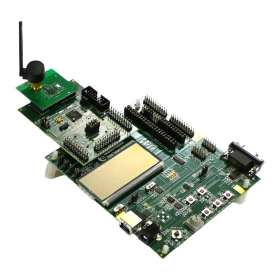
1. Kit Contents
3 x SmartRF05EB
2 x CCMSP-EM430F2618
3 x CC2520EM with antennas
1 x MSP-FET430UIF Debug Interface
Cables
Documentation
3B. DC Power
Alternatively a 4-10V DC power source
using the jack connector can be applied.
The centre pin is + and the sleeve is
connected to ground.
Set the power source jumper on the EB in
position USB/DC.
5. Set channel
Select a channel between 11 and 26
(2405-2480 MHz). The channel is
selected by navigating the joystick to the
right or left. Confirm the selection by
pressing Button 1.
2. Assemble the boards
Insert a CCMSP-EM430F2618 into both
the SmartRF05EB's. The connectors will
only fit in one position. Connect antennas
to both of the CC2520EM. Insert this
board into the CCMSP-EM430F2618.
These connectors will also fit in only one
position. Do not force the boards.
3C. USB
The SmartRf05EB can also be powered
from the USB cable.
Make sure that SmartRF Studio is
installed before connecting the USB. This
ensures that the correct USB drivers are
installed.
Set the power source jumper on the EB in
position USB/DC.
6. Select Transmitter/Receiver
Select transmitter on one of the
SmartRF05EB's and receiver on the other
by navigating with the joystick. Confirm
the selection by pressing Button 1 on
both devices. The receiver is now ready
to receive packets.
page 1
3A. Apply power
There are three different ways of applying
power to the SmartRf05EB. The first
method is to insert 2 AA batteries to the
battery connectors underneath the board.
Set the power source jumper on the
SmartRf05EB in position Battery.
4. Packet Error Rate tester
When power is applied to the board set
the power switch in the ON position and
the PER test program will start. The LCD
will display the screen as shown in the
picture above. Press Button 1 to enter the
menu.
7. Select Output Power
On the transmitter node, selection of TX
output power and burst size (number of
packets to send) is also needed. Select
TX output power by navigating the
joystick, either -4 dBm, 0 dBm or 4 dBm,
and confirm with Button 1.
SWRU139
Advertisement

Related Manuals for Texas Instruments CC2520DK


Summary of Contents for Texas Instruments CC2520DK
- Page 1 SWRU139 CC2520DK Quick Start Guide 1. Kit Contents 2. Assemble the boards 3A. Apply power There are three different ways of applying Insert a CCMSP-EM430F2618 into both power to the SmartRf05EB. The first the SmartRF05EB’s. The connectors will 3 x SmartRF05EB method is to insert 2 AA batteries to the only fit in one position.
-
Page 2: Document History
In order to use the SmartRF Studio the The user manuals are found on the the CCMSP-EM430F2618 board the CC2520EM is connected directly to the CC2520DK website: MSP430 Debug Interface is needed. SmartRf05EB. www.ti.com/cc2520dk Connect the MSP430 debug interface to... -
Page 3: Important Notice
TI as compliant with ISO/TS 16949 requirements. Buyers acknowledge and agree that, if they use any non-designated products in automotive applications, TI will not be responsible for any failure to meet such requirements. Following are URLs where you can obtain information on other Texas Instruments products and application solutions: Products...
Need help?
Do you have a question about the CC2520DK and is the answer not in the manual?
Questions and answers