Table of Contents
Advertisement
Quick Links
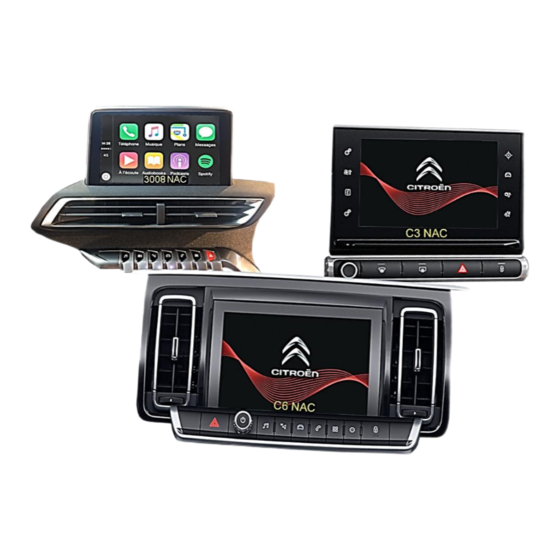
Opel, Citroen, Peugeot and Toyota vehicles
Video-inserter for front- and rear-view camera
Product features
Video-inserter for factory-infotainment systems
1 CVBS Input for rear-view camera
1 CVBS Input for front camera
2 CVBS video-inputs for after-market devices (e.g. USB-Player, DVB-T2 tuner)
Automatic switching to rear-view camera input on engagement of the reverse gear
Automatic front camera switching after reverse gear for 10 seconds
Activatable parking guide lines for the rear-view camera (not available for all vehicles)
Activatable PDC (not available for all vehicles)
Video-in-motion (ONLY for connected video-sources)
Video-inputs NTSC compatible
Version 26.05.2023
Video-inserter
RL4-NAC08
Compatible with
with NAC or RCC infotainment
and 7inch or 8inch monitor
and two additional video inputs
HW: CAM(V100)/(V52)
RL4-NAC08
Advertisement
Table of Contents

Subscribe to Our Youtube Channel
Related Manuals for NavLinkz RL4-NAC08


Summary of Contents for NavLinkz RL4-NAC08
- Page 1 Video-inserter RL4-NAC08 Compatible with Opel, Citroen, Peugeot and Toyota vehicles with NAC or RCC infotainment and 7inch or 8inch monitor Video-inserter for front- and rear-view camera and two additional video inputs Product features Video-inserter for factory-infotainment systems 1 CVBS Input for rear-view camera ...
-
Page 2: Table Of Contents
Case 2: Video interface does not receive the reverse gear signal 2.6. Connection - external keypad 2.7. Picture settings and guide lines 3. Interface operation 3.1. By NAVI button 3.2. By external keypad 4. Specifications 5. FAQ – Trouble shooting 6. Technical support Version 26.05.2023 HW: CAM(V100)/(V52) RL4-NAC08... -
Page 3: Prior To Installation
Read the manual prior to installation. Technical knowledge is necessary for installation. The place of installation must be free of moisture and away from heat sources. 1.1. Delivery contents Take down the serial number of the interface and store this manual for support purposes: ____________________ Version 26.05.2023 HW: CAM(V100)/(V52) RL4-NAC08... -
Page 4: Checking The Compatibility Of Vehicle And Accessories
5008 II since 02/2017, cable CAB-HSD-MF026 might be required Expert III since 03/2016, Partner III since 06/2018, Rifter since 09/2018, Traveller since 09/2016 ProAce since model year 2016, Toyota RCC (Bosch) ProAce City since 04/2020 Version 26.05.2023 HW: CAM(V100)/(V52) RL4-NAC08... - Page 5 HSD socket, the separately available cable CAB-HSD-MF026 can optionally be connected here. PDC and guidelines If the video interface does not receive the required information from the vehicle CAN-bus, neither guide-lines nor optical PDC display will be supported. Version 26.05.2023 HW: CAM(V100)/(V52) RL4-NAC08...
-
Page 6: Warning Notes
1.3. Warning notes: Damage to the head-unit is possible, if this RL4-NAC08 interface is installed to older Citroen / Peugeot SMEG or SMEG+ head-units (by Magneti Marelli)! Use this RL4-NAC08 interface only on Citroen/Opel/Peugeot/Toyota head-units NAC (by Continental) or RCC (Bosch). - Page 7 Dip 8 switch position (see following chapters) high version head-unit (double black male 4pin HSD on the backside) Please, carefully follow the manual for high or low version connection of the head unit and the assignment of the Dip-8 switch position! Version 26.05.2023 HW: CAM(V100)/(V52) RL4-NAC08...
-
Page 8: Connection Video-Interface
If you do not know the resolution, test both settings. Power reset after change of dip switches necessary. See the following chapters for detailed information. After each Dip-switch-change a power-reset of the Can-box has to be performed! Version 26.05.2023 HW: CAM(V100)/(V52) RL4-NAC08... -
Page 9: Adjustment - Power Supply Output (Dip 1)
Note: If you do not know the resolution, test both settings. Note: Dip4 and 7 are out of function and have to be set to OFF. After each Dip-switch-change a power-reset of the interface box has to be performed! Version 26.05.2023 HW: CAM(V100)/(V52) RL4-NAC08... -
Page 10: Settings Of The 4 Dip Switches (Can Function - Red)
Erfahrungswerte zu Einbauorten: Radio/Navi in Peugeot 2008 FY 2019 vehicles: Directly behind the display. Head Units in Peugeot 5008 and Opel Grandland X vehicles: Behind the centre console (for this, remove the panel in the passenger footwell). Version 26.05.2023 HW: CAM(V100)/(V52) RL4-NAC08... -
Page 11: Connection Schema
2.2. Connection schema Version 26.05.2023 HW: CAM(V100)/(V52) RL4-NAC08... -
Page 12: Connection - Picture Signal Cable
4pin HSD connector of the enclosed 4pin HSD harness. Connect the waterblue coloured female 4pin HSD connector to the previously become free black 4pin HSD connector at the rearside of the head unit. Version 26.05.2023 HW: CAM(V100)/(V52) RL4-NAC08... -
Page 13: High Version Head Unit (2 X 4 Pin Hsd)
Attention: The picture’s representation of the double 4-pin HSD connector may be reversed. Make sure that the white 4pin HSD connector is reconnected to the same position of the head unit, where it has been connected before! Version 26.05.2023 HW: CAM(V100)/(V52) RL4-NAC08... -
Page 14: Connection- Power / Can
Connect the singel four cables of the POWER / CAN cable to ACC and exactely to the 22pin connector’s shown chambers, as the vehicle’s cable colours may vary! Connect the power / CAN cable’s female 10pin connector to the 10pin connector of the video interface. Version 26.05.2023 HW: CAM(V100)/(V52) RL4-NAC08... -
Page 15: Installation With Analogue Connection (Without Can-Bus)
Connect the female 12pin connector of the 12pin interface cable to the male 12pin connector of the video interface. Connect the 12pin interface cable’s purple coloured wire Manual ACC to +12V or to +12V S-contact terminal 86s +12V (e.g. glove compartment illumination). Version 26.05.2023 HW: CAM(V100)/(V52) RL4-NAC08... -
Page 16: Power Supply Output
+12V (max. 3A) when reverse gear is engaged incl. 10 seconds delay after reverse gear is disengaged and +12V by manual switching to front camera by keypad (short press) Dip 1 OFF +12V (max. 3A) simulated ACC (while CAN has activity) Version 26.05.2023 HW: CAM(V100)/(V52) RL4-NAC08... -
Page 17: Connection - Video Sources
Connect the front camera’s video RCA connector to the 12pin interface cable’s female RCA connector „Front V3“. Connect the video RCA of the AV source 1 and 2 to the 12pin interface cable’s female RCA connector “Left (V1)” ”Right (V2)”. Version 26.05.2023 HW: CAM(V100)/(V52) RL4-NAC08... -
Page 18: Audio Insertion
Note: In addition, a manual switch-over to the front camera input is possible via keypad (short press) from any image mode. The power supply output supplies +12V then, too (if Dip 1 is set to ON and the front camera input is selected). Version 26.05.2023 HW: CAM(V100)/(V52) RL4-NAC08... -
Page 19: After-Market Rear-View Camera
The 12 V power supply for the rear-view camera (max 3A) has to be taken from the green wire of the 20pin cable to avoid an unnecessary, permanent power supply to the camera electronic. For the operation, both green cables “Reverse IN” “Reverse OUT” have to remain connected. Version 26.05.2023 HW: CAM(V100)/(V52) RL4-NAC08... -
Page 20: Case 2: Video Interface Does Not Receive The Reverse Gear Signal
Connect the output connector (87) of the relay to the rear-view camera’s power- cable, like you did it to the green “Reverse-IN” cable before. Connect permanent power / 12V to the relay’s input connector (30). Version 26.05.2023 HW: CAM(V100)/(V52) RL4-NAC08... -
Page 21: Connection - External Keypad
Connect the keypad’s female 4pin connector to the video-interface’s male 4pin connector. Note: Even if the switching through several video sources by the keypad mightn’t be required, the invisible connection and availability is strongly recommended. Version 26.05.2023 HW: CAM(V100)/(V52) RL4-NAC08... -
Page 22: Picture Settings And Guide Lines
Note: If the vehicle’s CAN communication does not support the video interface, the optical PDC and the guide-lines cannot be used, even if they’re once shown with the first operation! Version 26.05.2023 HW: CAM(V100)/(V52) RL4-NAC08... -
Page 23: Interface Operation
Factory video video IN1 video IN2 factory video … By dip switch deactivated inputs will be skipped. Switchover by vehicle buttons isn’t possible in all vehicles. In some vehicles the external keypad has to be used. Version 26.05.2023 HW: CAM(V100)/(V52) RL4-NAC08... -
Page 24: Specifications
7V - 25V Stand-by power drain Power 290mA @12V Video input 0.7V – 1V Video input formats NTSC Temperature range -40°C to +85°C Dimensions Video-Box 118 x 23 x 105 mm (W x H x D) Version 26.05.2023 HW: CAM(V100)/(V52) RL4-NAC08... -
Page 25: Faq - Trouble Shooting
Camera input picture fluorescent light which shines Test camera under natural light outside the garage. flickers. directly into the camera. Camera input picture is Protection sticker not Remove protection sticker from lens. bluish. removed from camera lens. Version 26.05.2023 HW: CAM(V100)/(V52) RL4-NAC08... -
Page 26: Technical Support
6pin to 8pin cable and isolate both ends. Technical Support Please note that direct technical support is only available for products purchased directly from NavLinkz GmbH. For products bought from other sources, contact your vendor for technical support. NavLinkz GmbH...
Need help?
Do you have a question about the RL4-NAC08 and is the answer not in the manual?
Questions and answers