Table of Contents
Advertisement
Quick Links
with Uconnect V2FRP infotainment
Video-inserter for front- and rear-view camera
Product features
Video-inserter for factory-infotainment systems
1 CVBS Input for rear-view camera
1 CVBS Input for front camera
2 CVBS video-inputs for after-market devices (e.g. USB-Player, DVB-T2 tuner)
Automatic switching to rear-view camera input on engagement of the reverse gear
Automatic front camera switching after reverse gear for 10 seconds
Video-in-motion (ONLY for connected video-sources)
Video-inputs NTSC compatible
Version 27.08.2021
Video-inserter
RL4-UCON5-CP
Compatible with
Jeep vehicles
and 5inch monitor
and two additional video sources
HW CAM(V98)/(V21)GD + CAM(V100)/(V20)GD
RL4-UCON5-CP
Advertisement
Table of Contents

Related Manuals for NavLinkz RL4-UCON5-CP


Summary of Contents for NavLinkz RL4-UCON5-CP
- Page 1 Video-inserter RL4-UCON5-CP Compatible with Jeep vehicles with Uconnect V2FRP infotainment and 5inch monitor Video-inserter for front- and rear-view camera and two additional video sources Product features Video-inserter for factory-infotainment systems 1 CVBS Input for rear-view camera 1 CVBS Input for front camera ...
-
Page 2: Table Of Contents
Connection – video inputs 2.9.1. Audio insertion 2.9.2. After-market front camera 2.9.3. After-market rear-view camera 2.10. Connection – external keypad Interface operation by external keypad Picture settings Specifications Frequently asked questions Technical support Version 27.08.2021 HW CAM(V98)/(V21)GD + CAM(V100)/(V20)GD RL4-UCON5-CP... -
Page 3: Prior To Installation
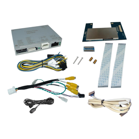
1. Prior to installation Read the manual prior to installation. Technical knowledge is necessary for installation. The place of installation must be free of moisture and away from heat sources. 1.1. Delivery contents Version 27.08.2021 HW CAM(V98)/(V21)GD + CAM(V100)/(V20)GD RL4-UCON5-CP... -
Page 4: Checking The Interface Compatibility Of Vehicle And Accessories
1.3.1. Connectors - video-interface The video-interface converts the video signals of connected after-market sources in a factory monitor compatible picture signal which is inserted in the factory monitor, by using separate trigger options. Version 27.08.2021 HW CAM(V98)/(V21)GD + CAM(V100)/(V20)GD RL4-UCON5-CP... -
Page 5: Connectors - Daughter Pcb
1.3.2. connectors – daughter PCB Version 27.08.2021 HW CAM(V98)/(V21)GD + CAM(V100)/(V20)GD RL4-UCON5-CP... -
Page 6: Dip-Switch Settings
No function Set to OFF No function No function Set to OFF *The front camera will automatically be switched for 10 seconds after disengaging the reverse gear. See the following chapters for detailed information. Version 27.08.2021 HW CAM(V98)/(V21)GD + CAM(V100)/(V20)GD RL4-UCON5-CP... -
Page 7: Activating The Front Camera Input (Dip 1)
Dip position down is ON and position up is OFF. Set all dip switches to off Vehicle/Navigation Dip 1 Dip 2 Dip 3 Dip 4 All vehicles Version 27.08.2021 HW CAM(V98)/(V21)GD + CAM(V100)/(V20)GD RL4-UCON5-CP... -
Page 8: Installation
Place of installation The video interface is designated to be connected behind the vehicle`s head unit. The daughter PCB shell be installed and connected inside the factory head unit behind the monitor panel. Version 27.08.2021 HW CAM(V98)/(V21)GD + CAM(V100)/(V20)GD RL4-UCON5-CP... -
Page 9: Connection Scheme
2.2. Connection Scheme Version 27.08.2021 HW CAM(V98)/(V21)GD + CAM(V100)/(V20)GD RL4-UCON5-CP... -
Page 10: Installation - Ribbon Cables Into The Monitor Panel
Remove the board underneath and put it aside. Unscrew the 5 screws and remove the sheet metal part underneath. Attention: It may be necessary to disconnect a small antenna cable from the board! Version 27.08.2021 HW CAM(V98)/(V21)GD + CAM(V100)/(V20)GD RL4-UCON5-CP... - Page 11 Connect and clip-in the enclosed single 40pin ribbon cable to the previously released 40pin ribbon cable base of the monitor board. Connect and clip-in the opposite side of that 40pin ribbon cable to the 40pin ribbon cable base "IN" of the daughter PCB. Version 27.08.2021 HW CAM(V98)/(V21)GD + CAM(V100)/(V20)GD RL4-UCON5-CP...
-
Page 12: Warning Notes, Concerning The Installation Of Ribbon Cables
(protect with fabric tape if necessary). Replace the two original screws, as shown in the picture, with the enclosed longer screws and fix the daughter PCB to the housing by using the enclosed spacers. Version 27.08.2021 HW CAM(V98)/(V21)GD + CAM(V100)/(V20)GD RL4-UCON5-CP... -
Page 13: Connection - Picture Signal Cable
2.5. Connection – picture signal cable Connect the opposite female 20pin connector of the pre-CONNECTED 20pin picture signal cable to the male 20pin connector of the video interface. Version 27.08.2021 HW CAM(V98)/(V21)GD + CAM(V100)/(V20)GD RL4-UCON5-CP... -
Page 14: Connection - 10Pin Power Cable
Connect the single black cable to the vehicle’s negative Ground (see diagram above). Note: The single blue wire and the single grey wire of the 10-Pin Power/CAN cable stay unconnected and have to be isolated, as their connection may cause malfunctions to the system. Version 27.08.2021 HW CAM(V98)/(V21)GD + CAM(V100)/(V20)GD RL4-UCON5-CP... -
Page 15: Connection - Purple Wire
Connect the female 12pin connector of the 12pin interface cable to the male 12pin connector of the video interface. Connect the 12pin interface cable’s purple coloured wire Manual ACC to +12V ACC terminal 15 or to +12V S-contact terminal 86s +12V (e.g. glove compartment illumination). Version 27.08.2021 HW CAM(V98)/(V21)GD + CAM(V100)/(V20)GD RL4-UCON5-CP... -
Page 16: Power Supply Output
+12V (max. 3A) when reverse gear is engaged incl. 10 seconds delay after reverse gear is disengaged and +12V by manual switching to front camera by keypad (short press) Dip 1 OFF +12V (max. 3A) ACC Version 27.08.2021 HW CAM(V98)/(V21)GD + CAM(V100)/(V20)GD RL4-UCON5-CP... - Page 17 Connect the front camera’s video RCA connector to the 12pin interface cable’s female RCA connector „Front V3“. Connect the video RCA of the AV source 1 and 2 to the 12pin interface cable’s female RCA connector “Left (V1)” ”Right (V2)”. Version 27.08.2021 HW CAM(V98)/(V21)GD + CAM(V100)/(V20)GD RL4-UCON5-CP...
-
Page 18: Audio Insertion
(short press) from any image mode. The power supply output gives +12V then, as well (if Dip 1 is set to ON and the front camera input is selected). Attention: A long press of the external keypad push button will switch the interface to the next source. Version 27.08.2021 HW CAM(V98)/(V21)GD + CAM(V100)/(V20)GD RL4-UCON5-CP... -
Page 19: After-Market Rear-View Camera
Connect the output connector (87) of the relay to the rear-view camera’s power- cable, like you did it to the green “Reverse-IN” cable before. Connect permanent power / 12V to the relay’s input connector (30). Version 27.08.2021 HW CAM(V98)/(V21)GD + CAM(V100)/(V20)GD RL4-UCON5-CP... -
Page 20: Connection - External Keypad
Connect the keypad’s female 4pin connector to the 12pin interface cable’s male 4pin connector. Note: Even if the switching through several video sources by the keypad mightn’t be required, the keypad’s invisible connection and availability is strongly recommended. Version 27.08.2021 HW CAM(V98)/(V21)GD + CAM(V100)/(V20)GD RL4-UCON5-CP... -
Page 21: Interface Operation By External Keypad
Short press of keypad (only if DIP 1 is set to ON) By short pressing the external keypad, the video interfaces switches from the factory video to the front camera input and back to factory video. Version 27.08.2021 HW CAM(V98)/(V21)GD + CAM(V100)/(V20)GD RL4-UCON5-CP... -
Page 22: Picture Settings
Saturation Position H (horizontal) Position V (vertical) IR-AV1/2 (no function) Guide L/R (no function) UI-CNTRL (no function) Size H/V (picture size horizontal/vertical) Note: To adjust the reverse picture settings, engage the reverse gear. Version 27.08.2021 HW CAM(V98)/(V21)GD + CAM(V100)/(V20)GD RL4-UCON5-CP... -
Page 23: Specifications
Stand-by power drain 10mA Power 120mA @12V Video input 0.7V - 1V Video input formats NTSC Temperature range -40°C to +85°C Dimensions daughter PCB 116 x 25 x 88mm (W x H x D) Version 27.08.2021 HW CAM(V98)/(V21)GD + CAM(V100)/(V20)GD RL4-UCON5-CP... - Page 24 Test camera under natural light outside the garage. flickers. directly into the camera. Camera input picture is Protection sticker not Remove protection sticker from lens. bluish. removed from camera lens. Version 27.08.2021 HW CAM(V98)/(V21)GD + CAM(V100)/(V20)GD RL4-UCON5-CP...
-
Page 25: Technical Support
6pin to 8pin cable and isolate both ends. Technical Support Please note that direct technical support is only available for products purchased directly from NavLinkz GmbH. For products bought from other sources, contact your vendor for technical support. NavLinkz GmbH...
Need help?
Do you have a question about the RL4-UCON5-CP and is the answer not in the manual?
Questions and answers