Table of Contents
Advertisement
Quick Links
All manuals and user guides at all-guides.com
r.LiNK Video inserter
RL4-LR17
Compatible with
Land Rover and Jaguar vehicles
with Incontrol Touch Pro Duo infotainment
and 10.2 inch monitor
Video-inserter for front- and rear-view camera
and two additional video inputs
Product features
Video-inserter for factory-infotainment systems
1 CVBS Input for rear-view camera
1 CVBS Input for front camera
2 CVBS Video-inputs for after-market Video sources (e.g. USB-Player, DVB-T2
Tuner)
Automatic switching to rear-view camera input on engagement of the reverse gear
Automatic front camera switching after reverse gear for 10 seconds
Activatable parking guide lines for rear-view camera (not available for all vehicles)
Video-in-motion (ONLY for connected video-sources)
Video-inputs NTSC compatible
Version 10.08.2020
HW:CAM(V98)/(V31/ZK)
RL4-LR17
Advertisement
Table of Contents

Related Manuals for NavLinkz r.LiNK RL4-LR17


Summary of Contents for NavLinkz r.LiNK RL4-LR17
- Page 1 All manuals and user guides at all-guides.com r.LiNK Video inserter RL4-LR17 Compatible with Land Rover and Jaguar vehicles with Incontrol Touch Pro Duo infotainment and 10.2 inch monitor Video-inserter for front- and rear-view camera and two additional video inputs Product features ...
-
Page 2: Table Of Contents
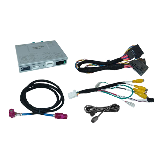
All manuals and user guides at all-guides.com Contents 1. Prior to installation 1.1. Delivery contents 1.2. Checking the compatibility of vehicle and accessories 1.3. Connection video interface 1.4. Settings of the 8 Dip switches (black) 1.4.1. Activating the front camera input (dip 1) 1.4.2. -
Page 3: Prior To Installation
All manuals and user guides at all-guides.com Legal Information By law, watching moving pictures while driving is prohibited, the driver must not be distracted. We do not accept any liability for material damage or personal injury resulting, directly or indirectly, from installation or operation of this product. Apart from using this product in an unmoved vehicle, it should only be used to display fixed menus or rear-view- camera video when the vehicle is moving (for example the MP3 menu for DVD upgrades). -
Page 4: Checking The Compatibility Of Vehicle And Accessories
All manuals and user guides at all-guides.com 1.2. Checking the compatibility of vehicle and accessories Requirements Brand Compatible vehicles Compatible systems Range Rover since model year 2018 Range Rover Sport since model year 2018 Incontrol Touch Pro Duo Land Rover Range Rover Velar since model year 2017 with 10.2 inch 24:9 monitor (glossy) Range Rover Evoque since model year 2020... -
Page 5: Connection Video Interface
All manuals and user guides at all-guides.com 1.3. Connection video interface The video-interface converts the video signals of connected after-market sources in a factory monitor compatible picture signal which is inserted in the factory monitor, by using separate trigger options. Further it reads the vehicle’s digital signals out of the vehicle’s CAN-bus and converts them for the video interface. -
Page 6: Activating The Front Camera Input (Dip 1)
All manuals and user guides at all-guides.com 1.4.1. Activating the front camera input (dip 1) If set to ON, the interface switches for 10 seconds from the rear-view camera to the front camera input after having disengaged the reverse gear. In addition, a manual switch-over to the front camera input is possible via keypad (short press) from any image mode. -
Page 7: Settings Of The 4 Dip Switches (Can Function - Red)
All manuals and user guides at all-guides.com 1.5. Settings of the 4 Dip switches (CAN functions – red) All 4 dip-switches of the video interface have no function for normal use and have to be set to OFF. Dip position “down” is ON and position up is OFF. Navigation / system Dip 1 Dip 2... -
Page 8: Monitor Removal - Example Land Rover
All manuals and user guides at all-guides.com 2.2. Monitor removal – example Land Rover Version 10.08.2020 HW:CAM(V98)/(V31/ZK) RL4-LR17... -
Page 9: Note For Test Run
All manuals and user guides at all-guides.com 2.3. Note for test run In vehicles in which the climate control system is operated by the touchscreen monitor, it is necessary to have the monitor connected for an interface test run. (Concerns e.g. all Land Rover and some other vehicles) Version 10.08.2020 HW:CAM(V98)/(V31/ZK) RL4-LR17... -
Page 10: Connection Schema
All manuals and user guides at all-guides.com 2.4. Connection schema Version 10.08.2020 HW:CAM(V98)/(V31/ZK) RL4-LR17... -
Page 11: Connection - Picture Signal Cable
All manuals and user guides at all-guides.com 2.5. Connection – picture signal cable Disconnect the female HSD connector of the vehicle harness from the rear-side of the ”HU IN” factory monitor and connect it to the waterblue coloured HSD connector of the video interface. - Page 12 All manuals and user guides at all-guides.com Note: The colours of the HSD connectors at monitor and head unit may vary. The picture signal cable’s connecting direction doesn’t have an impact on the system’s function, for that the angled and not-angled HSD connectors are allowed to be interchanged, depending on the HSD connectors mounting space at the monitor.
-
Page 13: Analog Power Supply For The Video Interface
All manuals and user guides at all-guides.com 2.6. Analog power supply for the video interface If, after connecting the PNP harness, no interface LED lightens up while the ignition is turned on, the purple coloured wire Manual ACC of the 12pin interface cable has to be connected additionally to S-contact terminal 86s +12V (e.g. -
Page 14: Power Supply Output
All manuals and user guides at all-guides.com 2.7. Power supply output The red power supply output ACC/front cam out 12V (max 3A) can be used to power an external source and has a different assignment, depending on the position of dip switch 1 (of 8 dips): Function Dip 1 ON... -
Page 15: Connection - Video-Sources
All manuals and user guides at all-guides.com 2.8. Connection - video sources It is possible to connect an after-market rear-view camera, an after-market front camera and two more video sources to the video-interface. Before a final installation of the video sources, we recommend a test-run to ensure the compatibility of vehicle and interface. -
Page 16: Audio Insertion
All manuals and user guides at all-guides.com 2.8.1. Audio-insertion This interface is only able to insert video signals into the factory infotainment. If an AV- source is connected, the audio insertion has to be done by the factory audio AUX input or an FM-modulator. -
Page 17: After-Market Rear-View Camera
All manuals and user guides at all-guides.com 2.8.3. After-market rear-view camera Some vehicles have a different reverse gear code on the CAN-bus which the video-interface is not compatible with. Therefore, there are two different ways of installation. If the video interface receives a signal of the reverse gear, the green wire “Reverse-OUT”... -
Page 18: Case 2Interface Does Not Receive The Reverse Gear Signal
All manuals and user guides at all-guides.com 2.8.3.2. Case 2: Interface does not receive the reverse gear signal If the video interface does not deliver +12V on the green wire of the 12pin cable when reverse gear is engaged (not all vehicles are compatible), an external switching signal from the reverse gear light is required. -
Page 19: Connection - Video-Interface And External Keypad
All manuals and user guides at all-guides.com 2.9. Connection - video-interface and external keypad Connect the female 4pin connector of the keypad to the male 4pin connector of the 12pin interface cable. Note: Even if switching through several video sources by the keypad mightn’t be required, the invisible connection and availability is strongly recommended. -
Page 20: Picture Settings
All manuals and user guides at all-guides.com 2.10. Picture settings The picture settings are adjustable by the 3 push-buttons on the video-interface. Press the MENU button to open the OSD settings menu or to switch to the next menu item. Press UP and DOWN to change the selected value. -
Page 21: Interface Operation
All manuals and user guides at all-guides.com 3. Interface operation 3.1. By factory touch screen To switch the interface’s activated video sources, the factory touch screen can be used. Make a long touch of the left top corner of the factory touch screen to switch the video- source. -
Page 22: By Keypad
All manuals and user guides at all-guides.com 3.2. By keypad Alternatively or additionally to the factory infotainment buttons, the interface’s external keypad can be used to switch the enabled inputs. Even if not needed, the keypad should always remain connected to the video interface for support purposes. (see next page). -
Page 23: Faq - Trouble Shooting-Interface Functions
All manuals and user guides at all-guides.com FAQ – Trouble shooting Interface functions For any troubles which may occur, check the following table for a solution before requesting support from your vendor. Symptom Reason Possible solution Not all connectors have been reconnected to factory head- Connect missing connectors. -
Page 24: Technical Support
6pin to 8pin cable and isolate both ends. Technical Support Please note that direct technical support is only available for products purchased directly from NavLinkz GmbH. For products bought from other sources, contact your vendor for technical support. NavLinkz GmbH...
Need help?
Do you have a question about the r.LiNK RL4-LR17 and is the answer not in the manual?
Questions and answers