Table of Contents
Advertisement
Quick Links
Opel vehicles with R4.0 IntelliLink system
and 7inch monitor with DIN-cage attached
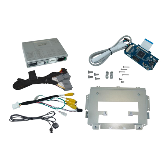
Video-inserter for front- and rear-view camera
Product features
• Video-inserter for factory infotainment systems
• 1 CVBS Input for rear-view camera
• 1 CVBS Input for front camera
• 2 CVBS Video-inputs for after-market Video sources (e.g. USB-Player, DVB-T2
Tuner)
• Automatic switching to rear-view camera input on engagement of reverse gear
• Automatic front camera switching after reverse gear for 10 seconds
• Activatable parking guide lines for the rear-view camera (not available on all
vehicles)
• Video-in-motion in drive mode (ONLY for connected video-sources)
• Video-inputs PAL and NTSC compatible
Version 01.04.2022
Video-inserter
RL4-R40
Compatible with
and two additional video inputs
HW: CAM(V100)/(V32)
RL4-R40
Advertisement
Table of Contents

Subscribe to Our Youtube Channel
Related Manuals for NavLinkz RL4-R40


Summary of Contents for NavLinkz RL4-R40
- Page 1 Video-inserter RL4-R40 Compatible with Opel vehicles with R4.0 IntelliLink system and 7inch monitor with DIN-cage attached Video-inserter for front- and rear-view camera and two additional video inputs Product features • Video-inserter for factory infotainment systems • 1 CVBS Input for rear-view camera •...
-
Page 2: Table Of Contents
Case 2: Video interface does not receive the reverse gear signal 2.8. Connecting video-interface and external keypad 2.9. Picture settings and guide lines 3. Interface operation 3.1. By CALL OFF button 3.2. By keypad 4. Specifications 5. FAQ – Trouble shooting 6. Technical support Version 01.04.2022 HW: CAM(V100)/(V32) RL4-R40... -
Page 3: Prior To Installation
Read the manual prior to installation. Technical knowledge is necessary for installation. The place of installation must be free of moisture and away from heat sources. 1.1. Delivery contents Take down the serial number of the interface and store this manual for support purposes: ____________________ Version 01.04.2022 HW: CAM(V100)/(V32) RL4-R40... -
Page 4: Checking The Compatibility Of Vehicle And Accessories
The video-interface converts the connected after-market sources video signals into an digital RGB signal which is inserted in the factory monitor using separate trigger options and it reads vehicle’s digital signals out of the vehicle’s CAN-bus and converts them for the video interface. Version 01.04.2022 HW: CAM(V100)/(V32) RL4-R40... -
Page 5: Settings Of The 8 Dip Switches (Black)
OFF *The front camera will automatically be switched for 10 seconds after disengaging the reverse gear. See the following chapters for detailed information. After each Dip-switch-change a power-reset of the Can-box has to be performed! Version 01.04.2022 HW: CAM(V100)/(V32) RL4-R40... -
Page 6: Adjustment - Power Supply Output (Dip 1)
Dip position down is ON and position up is OFF. Navigation / Sy5tem Dip 1 Dip 2 Dip 3 Dip 4 R4.0 IntelliLink systems Set all 4 dips to OFF. After each Dip-switch-change a power-reset of the Can-box has to be performed! Version 01.04.2022 HW: CAM(V100)/(V32) RL4-R40... -
Page 7: Installation
The video-interface is performed to be installed at the backside of the head-unit. 2.1.2. Place of installation – daughter PCB The daughter PCB is performed to be installed with an exchange housing plate behind the head unit’s monitor panel. Version 01.04.2022 HW: CAM(V100)/(V32) RL4-R40... -
Page 8: Connection Schema
2.2. Connection schema Version 01.04.2022 HW: CAM(V100)/(V32) RL4-R40... -
Page 9: Connection To The Head-Unit
(Refer also to chapter “Connecting the ribbon cables”) Remove the Original monitor retaining plate and replace it with the exchange retaining-plate by using the original screws. Version 01.04.2022 HW: CAM(V100)/(V32) RL4-R40... -
Page 10: Connecting Ribbon Cables
2.3.2. Connecting the ribbon cables 2.3.2.1. Ribbon cable – 66pin Connect the daughter PCB’s pre-assembeled 66pin ribbon cable „IN PCB“ to the previously become free ribbon cable base of the monitor mainboard (heed the following warning notes!). Version 01.04.2022 HW: CAM(V100)/(V32) RL4-R40... - Page 11 „OUT-PNL“ of the daughter PCB’s rearside (heed the following warning notes!). Note: Due to the very short length of the ribbon cable, there’s only limited space for mounting available (heed the following warning notes!). Version 01.04.2022 HW: CAM(V100)/(V32) RL4-R40...
-
Page 12: Warning Notes, Concerning The Installation Of Ribbon Cables
2.4. Connection from monitor to the video interface Connect the female 20pin LVDS connector of the LVDS cable which is led out of the head unit, to the male 20pin connector of the video interface. Version 01.04.2022 HW: CAM(V100)/(V32) RL4-R40... -
Page 13: Connection To The Head-Unit - Power / Can
If the interface does not power off (all LED off!) when vehicle is in sleep-mode, the yellow wire has to be cut and the wire’s end which leads into the video-box has to be connected with external ACC. Version 01.04.2022 HW: CAM(V100)/(V32) RL4-R40... -
Page 14: Power Supply Output
+12V (max. 3A) when reverse gear is engaged incl. 10 seconds delay after reverse gear is disengaged and +12V by manual switching to front camera by keypad (short press) Dip 1 OFF +12V (max. 3A) simulated ACC (while CAN has activity) Version 01.04.2022 HW: CAM(V100)/(V32) RL4-R40... -
Page 15: Connection - Video Sources
Connect the front camera’s video RCA connector to the 12pin interface cable’s female RCA connector „Front V3“. Connect the video RCA of the AV source 1 and 2 to the 12pin interface cable’s female RCA connector “Left (V1)” ”Right (V2)”. Version 01.04.2022 HW: CAM(V100)/(V32) RL4-R40... -
Page 16: Audio-Insertion
Note: In addition, a manual switch-over to the front camera input is possible via keypad (short press) from any image mode. The power supply output gives +12V then, too (if Dip 1 is set to ON and the front camera input is selected). Version 01.04.2022 HW: CAM(V100)/(V32) RL4-R40... -
Page 17: After-Market Rear-View Camera
The 12 V power supply for the rear-view camera (max 3A) has to be taken from the green wire of the 12pin interface cable to avoid an unnecessary, permanent power supply to the camera electronic. Both green cables “Reverse IN” “Reverse OUT” have to remain connected. Version 01.04.2022 HW: CAM(V100)/(V32) RL4-R40... -
Page 18: Case 2: Video Interface Does Not Receive The Reverse Gear Signal
Connect the output connector (87) of the relay to the rear-view camera’s power- cable, like you did it to the green “Reverse-IN” cable before. Connect permanent power / 12V to the relay’s input connector (30). Version 01.04.2022 HW: CAM(V100)/(V32) RL4-R40... -
Page 19: Connecting Video-Interface And External Keypad
Connect the keypad’s female 4pin connector to the video-interface’s male 4pin connector. Note: Even if the switching through several video sources by the keypad mightn’t be required, the invisible connection and availability is strongly recommended. Version 01.04.2022 HW: CAM(V100)/(V32) RL4-R40... -
Page 20: Picture Settings And Guide Lines
PDC ON: Nur PDC wird angezeigt. Guide ON: Nur Guide lines angezeigt. ALL Off: Guide lines und PDC werden nicht angezeigt. Note: If the CAN-box does not support the vehicle’s CAN, the guide-lines cannot be used. Version 01.04.2022 HW: CAM(V100)/(V32) RL4-R40... -
Page 21: Interface Operation
Factory video video IN1 video IN2 factory video … By dip switch deactivated inputs will be skipped. Switchover by vehicle buttons isn’t possible in all vehicles. In some vehicles the external keypad has to be used. Version 01.04.2022 HW: CAM(V100)/(V32) RL4-R40... -
Page 22: By Keypad
➢ Short press of keypad (only if DIP 1 is set to ON) By short pressing the external keypad, the video interfaces witches from the factory video to the front camera input and back to factory video. Version 01.04.2022 HW: CAM(V100)/(V32) RL4-R40... -
Page 23: Specifications
7V - 25V Stand-by power drain Power 100mA @12V Video input 0.7V – 1V Video input formats PAL/NTSC Temperature range -40°C to +85°C Dimensions Video-Box 118 x 26 x 90mm (W x H x D) Version 01.04.2022 HW: CAM(V100)/(V32) RL4-R40... -
Page 24: Faq - Trouble Shooting
Camera input picture fluorescent light which shines Test camera under natural light outside the garage. flickers. directly into the camera. Camera input picture is Protection sticker not Remove protection sticker from lens. bluish. removed from camera lens. Version 01.04.2022 HW: CAM(V100)/(V32) RL4-R40... -
Page 25: Technical Support
6pin to 8pin cable and isolate both ends. Technical Support Please note that direct technical support is only available for products purchased directly from NavLinkz GmbH. For products bought from other sources, contact your vendor for technical support. NavLinkz GmbH...
Need help?
Do you have a question about the RL4-R40 and is the answer not in the manual?
Questions and answers