Table of Contents
Advertisement
Quick Links
with MGU infotainment and 10.25 or 12.3inch monitor and HSD+2 plug
Video-inserter for one rear-view camera, one front camera
Product features
Video-inserter for factory-infotainment systems
CVBS Input for one rear-view camera
CVBS Input for one front camera
2 CVBS Video-inputs for after-market Video sources (e.g. DVD-Player, DVB-T Tuner)
Automatic switching to rear-view camera input on engagement of the reverse gear
Automatic front camera switching after disengaging reverse gear for 10 seconds
Activatable parking guide lines for rear-view camera (not available for all vehicles)
Video-in-motion (ONLY for connected video-sources)
Video-inputs NTSC and PAL compatible
Version 08.07.2022
Video inserter
RL4-MGU
Compatible with
BMW
vehicles F-and G-series
and two additional video inputs
HW:CAM(V100)/(V30.3)
RL4-MGU
Advertisement
Table of Contents

Subscribe to Our Youtube Channel
Related Manuals for NavLinkz RL4-MGU


Summary of Contents for NavLinkz RL4-MGU
- Page 1 Video inserter RL4-MGU Compatible with vehicles F-and G-series with MGU infotainment and 10.25 or 12.3inch monitor and HSD+2 plug Video-inserter for one rear-view camera, one front camera and two additional video inputs Product features Video-inserter for factory-infotainment systems CVBS Input for one rear-view camera ...
-
Page 2: Table Of Contents
Case 2: Interface does not receive the reverse gear signal 2.6. Connection - video-interface and external keypad 2.7. Picture settings and guide lines 3. Interface operation 3.1. By factory infotainment button 3.2. By keypad 4. Specifications 5. FAQ – Trouble Shooting-Interface functions 6. Technical support Version 08.07.2022 HW:CAM(V100)/(V30.3) RL4-MGU... -
Page 3: Prior To Installation
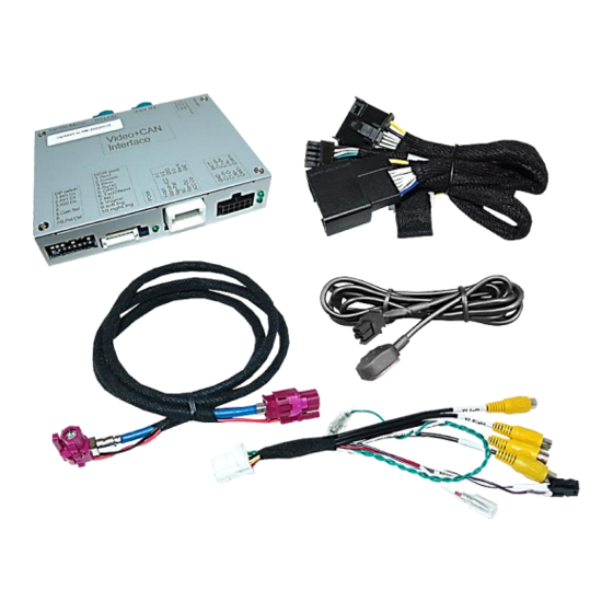
Due to changes in the production of the vehicle manufacturer there’s always a possibility of incompatibility. 1.1. Delivery contents 'ahmad@fosp.cn' Take down the serial number of the interface and store this manual for support purposes: ____________________ Version 08.07.2022 HW:CAM(V100)/(V30.3) RL4-MGU... -
Page 4: Checking The Compatibility Of Vehicle And Accessories
A manually front camera switching is also possible for 7 seconds. Dynamic guidelines Displayed dynamic guidelines are not available in all vehicles. PDC display The PDC display does not work in all vehicles. Version 08.07.2022 HW:CAM(V100)/(V30.3) RL4-MGU... -
Page 5: Boxes And Connectors - Video Interface
Try all possible combinations of Dips 7 and 8 to receive Monitor the best picture (quality and size) adjustments See the following chapters for detailed information. After each Dip-switch-change a power-reset of the Can-box has to be performed! Version 08.07.2022 HW:CAM(V100)/(V30.3) RL4-MGU... -
Page 6: Activating The Front Camera Input (Dip 1)
Dip7 and 8 change the monitor-specific video settings. Try all possible combinations of Dips 7 and 8 to receive the best picture (quality and size) After each Dip-switch-change a power-reset of the Can-box has to be performed! Version 08.07.2022 HW:CAM(V100)/(V30.3) RL4-MGU... -
Page 7: Installation
The video interface is prepared to be installed in a suitable location behind the factory head unit. In most vehicles, the centre console must be removed for this purpose. The connection is made to both, the head unit and the monitor. Version 08.07.2022 HW:CAM(V100)/(V30.3) RL4-MGU... -
Page 8: Connection Schema
2.2. Connection schema Version 08.07.2022 HW:CAM(V100)/(V30.3) RL4-MGU... -
Page 9: Connection To Factory Head Unit And Monitor
HSD+2 connectors mounting space. However, mixing up/interchanging the connections of „HU IN“ and „TO LCD“ will cause dysfunktion or even damage to the system! Note: The colours of the HSD+2 connectors at monitor and head unit may vary. Version 08.07.2022 HW:CAM(V100)/(V30.3) RL4-MGU... -
Page 10: Connection - Power And Can
16pin connector of the 10pin PNP Power / CAN cable. Connect the opposite female connector of the 10pin PNP Power / CAN cable to the previously become free male 16pin connector at the rear-side of the head unit. Version 08.07.2022 HW:CAM(V100)/(V30.3) RL4-MGU... -
Page 11: Analog Power Supply
Note: With analogue connection of the video interface (without CAN bus), the connection of the rear-view camera must also be made manually. (see point 2.5.2.2.: Case 2: Interface does not receive a reverse gear signal). Version 08.07.2022 HW:CAM(V100)/(V30.3) RL4-MGU... -
Page 12: Power Supply Output
+12V (max. 3A) when reverse gear is engaged incl. 10 seconds delay* after reverse gear is disengaged and +12V by manual switching to front camera by keypad (short press) Dip 1 OFF +12V (max. 3A) ACC Version 08.07.2022 HW:CAM(V100)/(V30.3) RL4-MGU... -
Page 13: Connection - Video-Sources
Connect the video RCA of the front camera to the 12pin interface cable’s female RCA connector “V3 Front”. Connect the video RCA of the video source 1 and 2 to the female RCA connector “V1 Left” ”V2 Right” of the 12pin interface cable. Version 08.07.2022 HW:CAM(V100)/(V30.3) RL4-MGU... -
Page 14: Audio Insertion
“V4 Reverse” while the reverse gear is engaged. Additionally, the +12V (max. 3A) power supply for the rear-view camera can be taken from the green wire of the 12pin interface cable. Version 08.07.2022 HW:CAM(V100)/(V30.3) RL4-MGU... -
Page 15: Case 2: Interface Does Not Receive The Reverse Gear Signal
(86) of the relay. Connect the output connector (87) of the relay to the rear-view camera’s power- cable, like you did it to the green “Reverse-IN” cable before. Connect stabile and permanent +12V to the relay’s input connector (30). Version 08.07.2022 HW:CAM(V100)/(V30.3) RL4-MGU... - Page 16 The power supply output gives +12V then, as well (if Dip 1 is set to ON and the front camera input is selected). Attention: A long press of the external keypad push button will switch the interface to the next source. Version 08.07.2022 HW:CAM(V100)/(V30.3) RL4-MGU...
-
Page 17: Connection - Video-Interface And External Keypad
Connect the female 4pin connector of the keypad to the male 4pin connector of the 12pin interface cable. Note: Even if switching through several video sources by the keypad mightn’t be required, the invisible connection and availability is strongly recommended. Version 08.07.2022 HW:CAM(V100)/(V30.3) RL4-MGU... -
Page 18: Picture Settings And Guide Lines
If there is no communication between interface and the vehicle`s CAN-bus (several vehicles aren’t compatible), the reverse gear guide-lines can`t be shown during the vehicle’s operation, even if they once appear after having switched the system to powerless! Version 08.07.2022 HW:CAM(V100)/(V30.3) RL4-MGU... -
Page 19: Interface Operation
Alternatively or additionally to the factory infotainment buttons, the interface’s external keypad can be used to switch the enabled inputs. Even if not needed, the keypad should always remain connected to the video interface for support purposes. Version 08.07.2022 HW:CAM(V100)/(V30.3) RL4-MGU... -
Page 20: Specifications
Stand-by power drain 20mA Power 340mA @12V Video input 0.7V - 1V Video input formats NTSC and PAL Temperature range -40°C to +85°C Dimensions video-box 115 x 25 x 102 mm (W x H x D) Version 08.07.2022 HW:CAM(V100)/(V30.3) RL4-MGU... -
Page 21: Faq - Trouble Shooting-Interface Functions
Camera input picture fluorescent light which shines Test camera under natural light outside the garage. flickers. directly into the camera. Camera input picture is Protection sticker not Remove protection sticker from lens. bluish. removed from camera lens. Version 08.07.2022 HW:CAM(V100)/(V30.3) RL4-MGU... -
Page 22: Technical Support
6pin to 8pin cable and isolate both ends. Technical Support Please note that direct technical support is only available for products purchased directly from NavLinkz GmbH. For products bought from other sources, contact your vendor for technical support. NavLinkz GmbH...
Need help?
Do you have a question about the RL4-MGU and is the answer not in the manual?
Questions and answers