Table of Contents
Advertisement
Quick Links
Alfa Romeo, Citroen, Dodge, Fiat, Jeep and Peugeot vehicles
with Uconnect 5 VP2 / RA2 System
Video-inserter for front- and rear-view camera
Product features
Video-inserter for factory-infotainment systems
1 CVBS Input for rear-view camera
1 CVBS Input for front camera
2 CVBS video-inputs for after-market devices (e.g. USB-Player, DVB-T2 tuner)
Automatic switching to rear-view camera input on engagement of the reverse gear
Automatic front camera switching after reverse gear for 10 seconds
Video-in-motion (ONLY for connected video-sources)
Video-inputs NTSC and PAL compatible
Version 09.09.2021
Video-inserter
RL4-UCON5-F
Compatible with
and two additional video sources
HW CAM(V100)(V12)
RL4-UCON5-F
Advertisement
Table of Contents

Related Manuals for NavLinkz RL4-UCON5-F


Summary of Contents for NavLinkz RL4-UCON5-F
- Page 1 Video-inserter RL4-UCON5-F Compatible with Alfa Romeo, Citroen, Dodge, Fiat, Jeep and Peugeot vehicles with Uconnect 5 VP2 / RA2 System Video-inserter for front- and rear-view camera and two additional video sources Product features Video-inserter for factory-infotainment systems 1 CVBS Input for rear-view camera ...
-
Page 2: Table Of Contents
Case 1: Video-interface receives the reverse gear signal 2.9.3.2. Case 2: Video interface does not receive the reverse gear signal 2.10. Connection – external keypad 2.11. Picture settings 3. Interface operation 4. Specifications 5. FAQ – Trouble shooting 6. Technical support Version 09.09.2021 HW CAM(V100)(V12) RL4-UCON5-F... -
Page 3: Prior To Installation
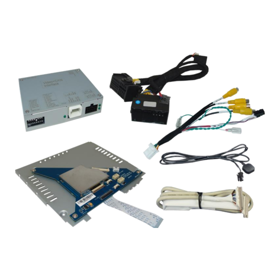
Read the manual prior to installation. Technical knowledge is necessary for installation. The place of installation must be free of moisture and away from heat sources. 1.1. Delivery contents Take down the serial number of the interface and store this manual for support purposes: ____________________ Version 09.09.2021 HW CAM(V100)(V12) RL4-UCON5-F... -
Page 4: Checking The Compatibility Of Vehicle And Accessories
After market front camera The front camera will automatically be switched for 10 seconds after disengaging the reverse gear. A manually front camera switching is possible by external keypad. Version 09.09.2021 HW CAM(V100)(V12) RL4-UCON5-F... -
Page 5: Connectors-Video Interface
Set to OFF No function Set to OFF No function No function Set to OFF *The front camera will automatically be switched for 10 seconds after disengaging the reverse gear. See the following chapters for detailed information. Version 09.09.2021 HW CAM(V100)(V12) RL4-UCON5-F... -
Page 6: Activating The Front Camera Input
Dip position down is ON and position up is OFF. Set all dip switches to off Vehicle/Navigation Dip 1 Dip 2 Dip 3 Dip 4 All vehicles Version 09.09.2021 HW CAM(V100)(V12) RL4-UCON5-F... -
Page 7: Installation
2.1. Place of installation – video-interface The video-interface is installed on the backside of the head-unit. 2.1.1. Place of installation - Exchange housing base plate with daugter PCB Version 09.09.2021 HW CAM(V100)(V12) RL4-UCON5-F... -
Page 8: Connection Schema
2.2. Connection schema Version 09.09.2021 HW CAM(V100)(V12) RL4-UCON5-F... -
Page 9: Connection To The Head-Unit - Lvds
Note: The connected ribbon cables have to be handled with care to avoid each damage of the sensitive electrical inducters. Position the Exchange housing base plate with the daugter PCB in place of the original base plate Version 09.09.2021 HW CAM(V100)(V12) RL4-UCON5-F... - Page 10 After a check of the perfect ribbon cable connection, in reverse order fold back and clip in the head-unit housing to the head-unit control panel and fix the exchange housing base plate to the head-unit’s housing. Version 09.09.2021 HW CAM(V100)(V12) RL4-UCON5-F...
-
Page 11: Exception Fot Chrysler Vehicles
2) The ribbon cable’s contacting side always has to correspond to the contacting side of the connector, concerning the mounting position. 3) Avoid cable contusion or cable injury caused by sharp-edged metal. Version 09.09.2021 HW CAM(V100)(V12) RL4-UCON5-F... -
Page 12: Head Unit - Frame Customizing
Connect the male beige-coloured 20pin connector of the 20pin RGB digital cable to the female 20pin connector of the daughter PCB. Pay special attention to the cable’s direction because its connectors both seem to be identical. (Strictly respect the lables „MONITOR SIDE“ „BOX SIDE“). Version 09.09.2021 HW CAM(V100)(V12) RL4-UCON5-F... -
Page 13: Connection - Pnp Quadlock Harness
Quadlock connector of the PNP Quadlock harness. Connect the female Quadlock connector of the PNP Quadlock harness to the male Quadlock connector of the head-unit. Version 09.09.2021 HW CAM(V100)(V12) RL4-UCON5-F... - Page 14 Connect the female 12pin connector of the 12pin interface cable to the male 12pin connector of the video interface. Connect the 12pin interface cable’s purple coloured wire Manual ACC S-contact terminal 86s +12V (e.g. glove compartment illumination). Version 09.09.2021 HW CAM(V100)(V12) RL4-UCON5-F...
-
Page 15: Power Supply Output
+12V (max. 3A) when reverse gear is engaged incl. 10 seconds delay after reverse gear is disengaged and +12V by manual switching to front camera by keypad (short press) Dip 1 OFF +12V (max. 3A) ACC Version 09.09.2021 HW CAM(V100)(V12) RL4-UCON5-F... -
Page 16: Connection - Video Sources
Connect the front camera’s video RCA connector to the 12pin interface cable’s female RCA connector „Front V3“. Connect the video RCA of the AV source 1 and 2 to the 12pin interface cable’s female RCA connector “Left (V1)” ”Right (V2)”. Version 09.09.2021 HW CAM(V100)(V12) RL4-UCON5-F... -
Page 17: Audio-Insertion
(short press) from any image mode. The power supply output gives +12V then, as well (if Dip 1 is set to ON and the front camera input is selected). Attention: A long press of the external keypad push button will switch the interface to the next source. Version 09.09.2021 HW CAM(V100)(V12) RL4-UCON5-F... -
Page 18: After-Market Rear-View Camera
The 12 V power supply for the rear-view camera (max 3A) has to be taken from the green wire of the 20pin cable to avoid an unnecessary permanent power supply to the camera electronic. For the operation, both green cables “Reverse IN” “Reverse OUT” have to stay connected. Version 09.09.2021 HW CAM(V100)(V12) RL4-UCON5-F... - Page 19 Connect the output connector (87) of the relay to the rear-view camera’s power- cable, like you did it to the green “Reverse-IN” cable before. Connect permanent power / 12V to the relay’s input connector (30). Version 09.09.2021 HW CAM(V100)(V12) RL4-UCON5-F...
-
Page 20: Connection - External Keypad
Connect the keypad’s female 4pin connector to the 12pin interface cable’s male 4pin connector. Note: Even if the switching through several video sources by the keypad mightn’t be required, the keypad’s invisible connection and availability is strongly recommended. Version 09.09.2021 HW CAM(V100)(V12) RL4-UCON5-F... -
Page 21: Interface Operation
Short press of keypad (only if DIP 1 is set to ON) By short pressing the external keypad, the video interfaces switches from the factory video to the front camera input and back to factory video. Version 09.09.2021 HW CAM(V100)(V12) RL4-UCON5-F... -
Page 22: Specifications
112mA @12V Video input 0.7V – 1V Video input formats PAL/NTSC RGB-video amplitude 0.7V with 75 Ohm impedance Temperature range -40°C to +85°C Dimensions Video-Box 115 x 25 x 89 mm (W x H x D) Version 09.09.2021 HW CAM(V100)(V12) RL4-UCON5-F... -
Page 23: Faq - Trouble Shooting
Camera input picture fluorescent light which shines Test camera under natural light outside the garage. flickers. directly into the camera. Camera input picture is Protection sticker not Remove protection sticker from lens. bluish. removed from camera lens. Version 09.09.2021 HW CAM(V100)(V12) RL4-UCON5-F... -
Page 24: Technical Support
6pin to 8pin cable and isolate both ends. Technical Support Please note that direct technical support is only available for products purchased directly from NavLinkz GmbH. For products bought from other sources, contact your vendor for technical support. NavLinkz GmbH...
Need help?
Do you have a question about the RL4-UCON5-F and is the answer not in the manual?
Questions and answers