Table of Contents
Advertisement
Quick Links
Compatible with Chrysler, Dodge, Jeep vehicles with
Uconnect 4C NAV UAV and 8.4inch monitor
Uconnect NAV UAX und 12inch monitor
Video-inserter for front- and rear-view camera
Product features
Video-inserter for factory-infotainment systems
1 CVBS Input for rear-view camera
1 CVBS Input for front camera
2 CVBS video-inputs for after-market devices (e.g. USB-Player, DVB-T2 tuner)
Automatic switching to rear-view camera input on engagement of the reverse gear
Automatic front camera switching after reverse gear for 10 seconds
Video-in-motion (ONLY for connected video-sources)
Video-inputs NTSC and PAL compatible
Version 20.08.2021
Video-inserter
RL4-UCON12
with separate head-unit
and two additional video sources
HW: CAM(100)/(V11+V41)
RL4-UCON12
Advertisement
Table of Contents

Related Manuals for NavLinkz RL4-UCON12


Summary of Contents for NavLinkz RL4-UCON12
- Page 1 Video-inserter RL4-UCON12 Compatible with Chrysler, Dodge, Jeep vehicles with Uconnect 4C NAV UAV and 8.4inch monitor Uconnect NAV UAX und 12inch monitor with separate head-unit Video-inserter for front- and rear-view camera and two additional video sources Product features Video-inserter for factory-infotainment systems ...
-
Page 2: Table Of Contents
Case 1: Interface receives the reverse gear signal 3.3.2. Case 2: Interface does not receive the reverse gear signal 3.4. Connection video-interface and keypad 3.5. Picture settings 4. Interface operation 5. Specifications 6. FAQ – Trouble Shooting-Interface functions 7. Technical support Version 20.08.2021 HW: CAM(100)/(V11+V41) RL4-UCON12... -
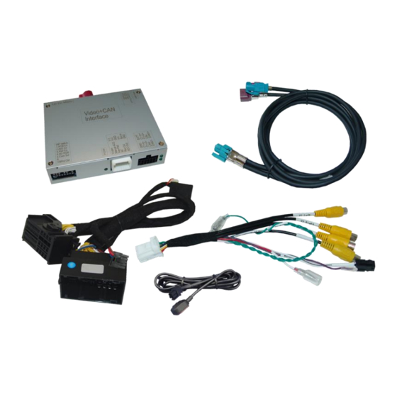
Page 3: Prior To Installation
The place of installation has to be free of moisture and away from heat sources. 1.1. Delivery contents Take down the serial number of the interface and store this manual for support purposes: ____________________ Version 20.08.2021 HW: CAM(100)/(V11+V41) RL4-UCON12... -
Page 4: Checking The Compatibility Of Vehicle And Accessories
A manually front camera switching is possible by external keypad. If the video interface does not receive the required information from the vehicle CAN-bus, the optical PDC display will not be supported. Version 20.08.2021 HW: CAM(100)/(V11+V41) RL4-UCON12... -
Page 5: Connectors - Video Interface
Further it reads the vehicle’s digital signals out of the vehicle’s CAN-bus and converts them for the video interface. Version 20.08.2021 HW: CAM(100)/(V11+V41) RL4-UCON12... -
Page 6: Dip Switch Settings
*The front camera will automatically be switched for 10 seconds after disengaging the reverse gear. After each Dip-switch-change a power-reset of the Video Interface has to be performed! See the following chapters for detailed information. Version 20.08.2021 HW: CAM(100)/(V11+V41) RL4-UCON12... -
Page 7: Activating The Front Camera Input (Dip 1)
If set to OFF, 9inch monitors are selected on the interface. Note: Dip4, 6 and 7 are out of function and have to be set to OFF. After each Dip-switch-change a power-reset of the Video Interface has to be performed! Version 20.08.2021 HW: CAM(100)/(V11+V41) RL4-UCON12... -
Page 8: Dip - Red
If the necessary stabilized power supply for the interface is not taken directly from the battery, the chosen connection has to be checked for being constantly stabile. The interface needs a permanent 12V source! 2.1. Place of installation The interface is designated to be connected behind the vehicle`s head-unit. Version 20.08.2021 HW: CAM(100)/(V11+V41) RL4-UCON12... -
Page 9: Connection Schema
2.2. Connection schema Version 20.08.2021 HW: CAM(100)/(V11+V41) RL4-UCON12... -
Page 10: Connection - Picture Signal Cable
Connection to the head unit may cause damage to the system! Note: No liability for vehicle wire colours and pin definition! Changes by the vehicle manufacturer are possible. The given information has to be verified by the installer. Version 20.08.2021 HW: CAM(100)/(V11+V41) RL4-UCON12... -
Page 11: Connection - Pnp Power / Can Cable
52pin connector of the enclosed PNP Power/CAN cable. Connect the enclosed PNP Power / CAN cable’s opposite female 52pin connector to the previously become free male 52pin connector of the head-unit. Version 20.08.2021 HW: CAM(100)/(V11+V41) RL4-UCON12... -
Page 12: Analogue Power Supply
Connect the female 12pin connector of the 12pin interface cable to the male 12pin connector of the video interface. Connect the 12pin interface cable’s purple coloured wire Manual ACC +12V ACC terminal 15 or to +12V S-contact terminal 86s +12V (e.g. glove compartment illumination). Version 20.08.2021 HW: CAM(100)/(V11+V41) RL4-UCON12... -
Page 13: Power Supply Output
+12V (max. 3A) when reverse gear is engaged incl. 10 seconds delay after reverse gear is disengaged and +12V by manual switching to front camera by keypad (short press) Dip 1 OFF +12V (max. 3A) ACC Version 20.08.2021 HW: CAM(100)/(V11+V41) RL4-UCON12... -
Page 14: Connection - Video Sources
Connect the front camera’s video RCA connector to the 12pin interface cable’s female RCA connector „Front V3“. Connect the video RCA of the AV source 1 and 2 to the 12pin interface cable’s female RCA connector “Left (V1)” ”Right (V2)”. Version 20.08.2021 HW: CAM(100)/(V11+V41) RL4-UCON12... -
Page 15: Audio Insertion
The power supply output gives +12V then, as well (if Dip 1 is set to ON and the front camera input is selected). Attention: A longer press of the external keypad push button will switch the interface to the next source! Version 20.08.2021 HW: CAM(100)/(V11+V41) RL4-UCON12... -
Page 16: After-Market Rear-View Camera
The 12 V power supply for the rear-view camera (max 3A) has to be taken from the 12pin interface cabl’s green wire “Reverse-OUT” to avoid an unnecessary, permanent power supply to the camera electronic. Both green cables “Reverse IN” “Reverse OUT” have to remain connected. Version 20.08.2021 HW: CAM(100)/(V11+V41) RL4-UCON12... -
Page 17: Case 2: Interface Does Not Receive The Reverse Gear Signal
Connect the output connector (87) of the relay to the rear-view camera’s power- cable, like you did it to the green “Reverse-IN” cable before. Connect permanent power / 12V to the relay’s input connector (30). Version 20.08.2021 HW: CAM(100)/(V11+V41) RL4-UCON12... -
Page 18: Connection Video-Interface And Keypad
Connect the keypad’s female 4pin connector to the 12pin interface cable’s male 4pin connector. Note: Even if the switching through several video sources by the keypad mightn’t be required, the keypad’s invisible connection and availability is strongly recommended. Version 20.08.2021 HW: CAM(100)/(V11+V41) RL4-UCON12... -
Page 19: Picture Settings
3 keys to pop up the menu, there are 2 options: H- Position, V-Position, which are used to set the picture location. All video channels can be adjusted separately. This can make the picture ideally fit the display. Version 20.08.2021 HW: CAM(100)/(V11+V41) RL4-UCON12... -
Page 20: Interface Operation
Video input 0.7V - 1V Video input formats NTSC / PAL RGB-video amplitude 0.7V with 75 Ohm impedance Temperature range -40°C to +85°C Dimensions video-box 117 x 26 x 103 mm (W x H x D) Version 20.08.2021 HW: CAM(100)/(V11+V41) RL4-UCON12... -
Page 21: Faq - Trouble Shooting-Interface Functions
Camera input picture fluorescent light which shines Test camera under natural light outside the garage. flickers. directly into the camera. Camera input picture is Protection sticker not Remove protection sticker from lens. bluish. removed from camera lens. Version 20.08.2021 HW: CAM(100)/(V11+V41) RL4-UCON12... -
Page 22: Technical Support
6pin to 8pin cable and isolate both ends. Technical Support Please note that direct technical support is only available for products purchased directly from NavLinkz GmbH. For products bought from other sources, contact your vendor for technical support. NavLinkz GmbH...
Need help?
Do you have a question about the RL4-UCON12 and is the answer not in the manual?
Questions and answers