Table of Contents
Advertisement
Quick Links
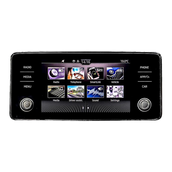
MIB3 Entry - Composition with 8.25inch monitor
MIB3 Entry - with 8.25inch monitor
MIB3 Entry with 8.25inch monitor
Video-inserter for front- and rear-view camera
Product features
• Video-inserter for factory-infotainment systems
• 1 CVBS Input for rear-view camera
• 1 CVBS Input for front camera
• 2 CVBS video-inputs for after-market devices (e.g. USB-Player, DVB-T2 tuner)
• Automatic switching to rear-view camera input on engagement of the reverse gear
• Automatic front camera switching after reverse gear for 10 seconds
• Activatable parking guide lines for rear-view camera (not available for all vehicles)
• Video-in-motion (ONLY for connected video-sources)
• Video-inputs NTSC and PAL compatible
Version 10.02.2022
Video-inserter
RL4-MIB3-E
Compatible with
VW
vehicles with
Seat
vehicles with
Skoda
vehicles with
and two additional video sources
HW CAM(V100) / (V10.3)
RL4-MIB3-E
Advertisement
Table of Contents

Related Manuals for NavLinkz RL4-MIB3-E


Summary of Contents for NavLinkz RL4-MIB3-E
- Page 1 Video-inserter RL4-MIB3-E Compatible with vehicles with MIB3 Entry - Composition with 8.25inch monitor Seat vehicles with MIB3 Entry - with 8.25inch monitor Skoda vehicles with MIB3 Entry with 8.25inch monitor Video-inserter for front- and rear-view camera and two additional video sources Product features •...
-
Page 2: Table Of Contents
Case 1: Interface receives the reverse gear signal 2.8.3.2. Case 2: Interface does not receive the reverse gear signal 2.9. Connection – external keypad Interface operation by external keypad Picture settings Specifications Frequently asked questions Technical support Version 10.02.2022 HW CAM(V100) / (V10.3) RL4-MIB3-E... -
Page 3: Prior To Installation
Prior to installation Read the manual prior to installation. Technical knowledge is necessary for installation. The place of installation has to be free of moisture and away from heat sources. 1.1. Delivery contents Version 10.02.2022 HW CAM(V100) / (V10.3) RL4-MIB3-E... -
Page 4: Checking The Interface Compatibility Of Vehicle And Accessories
The front camera will automatically be switched for 10 seconds after disengaging the reverse gear. A manually front camera switching is possible by external keypad. Guidelines Displayed guidelines are not available in all vehicles. Version 10.02.2022 HW CAM(V100) / (V10.3) RL4-MIB3-E... -
Page 5: Connectors - Video Interface
The video-interface (daughter PCB) converts the video signals of connected after-market sources in a factory monitor compatible picture signal which is inserted in the factory monitor, by using separate trigger options. 1.4. connectors – daughter PCB Version 10.02.2022 HW CAM(V100) / (V10.3) RL4-MIB3-E... -
Page 6: Dip-Switch Settings
Only the enabled video inputs can be accessed when switching through the interface’s video sources. It is recommended to enable only the required inputs, disabled inputs will be skipped when switching through the video-interfaces inputs. Version 10.02.2022 HW CAM(V100) / (V10.3) RL4-MIB3-E... -
Page 7: Rear-View Camera Setting (Dip 5)
By using the Dip-switches, the factory Head-unit or vehicle can be chosen which the interface will be connected to. Dip position down is ON and position up is OFF. Set all dip switches to off Vehicle/Navigation Dip 1 Dip 2 Dip 3 Dip 4 All vehicles Version 10.02.2022 HW CAM(V100) / (V10.3) RL4-MIB3-E... -
Page 8: Installation
2.1. Place of installation The video interface is designated to be connected behind the vehicle`s head unit. The daughter PCB is prepared to be connected inside the factory head unit). Version 10.02.2022 HW CAM(V100) / (V10.3) RL4-MIB3-E... -
Page 9: Connection Scheme
2.2. Connection scheme Version 10.02.2022 HW CAM(V100) / (V10.3) RL4-MIB3-E... -
Page 10: Installation - Daughter Pcb
Installation – daughter PCB Remove the factory monitor and open it`s housing. The daughter PCB is built to be installed into the optical lead between the monitor panel and mainboard of the vehicles monitor. Version 10.02.2022 HW CAM(V100) / (V10.3) RL4-MIB3-E... -
Page 11: Warning Notes, Concerning The Installation Of Ribbon Cables
2.4. Connection – 20pin picture signal cable Connect the female 20pin connector of the daughter PCB’s pre-connected 20pin picture signal cable to the video interface’s male 20pin connector. Version 10.02.2022 HW CAM(V100) / (V10.3) RL4-MIB3-E... -
Page 12: Connection - 10Pin Power / Can Cable
4 cables to the vehicle’s CAN high wire and isolate the connection Connect the single red wire to stabile +12V terminal Connect the single black cable to the vehicle’s negative Ground. Version 10.02.2022 HW CAM(V100) / (V10.3) RL4-MIB3-E... -
Page 13: Analogue Power Supply
Connect the female 12pin connector of the 12pin interface cable to the male 12pin connector of the video interface. Connect the 12pin interface cable’s purple coloured wire Manual ACC to +12V Ignition power or to +12V S-contact terminal 86s +12V (e.g. glove compartment illumination). Version 10.02.2022 HW CAM(V100) / (V10.3) RL4-MIB3-E... -
Page 14: Power Supply Output
+12V (max. 3A) when reverse gear is engaged plus 10 seconds delay after reverse gear is disengaged and +12V when manually switched to front camera by keypad (short press) Dip 1 OFF +12V permanent (max. 3A) ACC Version 10.02.2022 HW CAM(V100) / (V10.3) RL4-MIB3-E... - Page 15 Limitation: In the inserted video picture (front and rear view camera, video 1 and video 2), a 5mm wide black strip can be seen on the left-hand side that cannot be faded out. Version 10.02.2022 HW CAM(V100) / (V10.3) RL4-MIB3-E...
- Page 16 Connect the front camera’s video RCA connector to the 12pin interface cable’s female RCA connector „Front V3“. Connect the video RCA of the AV source 1 and 2 to the 12pin interface cable’s female RCA connector “Left (V1)” ”Right (V2)”. Version 10.02.2022 HW CAM(V100) / (V10.3) RL4-MIB3-E...
-
Page 17: Audio Insertion
(short press) from any image mode. The power supply output gives +12V then, as well (if Dip 1 is set to ON and the front camera input is selected). Attention: A long press of the external keypad push button will switch the interface to the next source. Version 10.02.2022 HW CAM(V100) / (V10.3) RL4-MIB3-E... -
Page 18: After-Market Rear-View Camera
The 12 V power supply for the rear-view camera (max 3A) has to be taken from the 12pin interface cabl’s green wire “Reverse-OUT” to avoid an unnecessary, permanent power supply to the camera electronic. Both green cables “Reverse IN” “Reverse OUT” have to remain connected. Version 10.02.2022 HW CAM(V100) / (V10.3) RL4-MIB3-E... -
Page 19: Case 2: Interface Does Not Receive The Reverse Gear Signal
Connect the output connector (87) of the relay to the rear-view camera’s power- cable, like you did it to the green “Reverse-IN” cable before. Connect permanent power / 12V to the relay’s input connector (30). Version 10.02.2022 HW CAM(V100) / (V10.3) RL4-MIB3-E... -
Page 20: Connection - External Keypad
Connect the keypad’s female 4pin connector to the 12pin interface cable’s male 4pin connector. Note: Even if the switching through several video sources by the keypad mightn’t be required, the keypad’s invisible connection and availability is strongly recommended. Version 10.02.2022 HW CAM(V100) / (V10.3) RL4-MIB3-E... -
Page 21: Interface Operation By External Keypad
➢ Short press of keypad (only if DIP 1 is set to ON) By short pressing the external keypad, the video interfaces switches from the factory video to the front camera input and back to factory video. Version 10.02.2022 HW CAM(V100) / (V10.3) RL4-MIB3-E... -
Page 22: Picture Settings
Video input formats NTSC/PAL Temperature range -40°C to +85°C Dimensions Video-box 117 x 26 x 90mm (W x H x D) Dimensions daughter PCB 126 x 6 x 74mm (W x H x D) Version 10.02.2022 HW CAM(V100) / (V10.3) RL4-MIB3-E... - Page 23 Test camera under natural light outside the garage. flickers. directly into the camera. Camera input picture is Protection sticker not Remove protection sticker from lens. bluish. removed from camera lens. Version 10.02.2022 HW CAM(V100) / (V10.3) RL4-MIB3-E...
-
Page 24: Technical Support
6pin to 8pin cable and isolate both ends. Technical Support Please note that direct technical support is only available for products purchased directly from NavLinkz GmbH. For products bought from other sources, contact your vendor for technical support. NavLinkz GmbH...
Need help?
Do you have a question about the RL4-MIB3-E and is the answer not in the manual?
Questions and answers