Table of Contents

Subscribe to Our Youtube Channel
Related Manuals for ORTAL Wilderness 60HH Front Facing


Summary of Contents for ORTAL Wilderness 60HH Front Facing
- Page 1 Installation and Operation Manual Wilderness 60HH Series Wilderness 60HH Series Fireplaces: Wilderness 60HH Front Facing Wilderness 60HH Corner (RS/LS) Wilderness 60HH Three Sided (TS) Ortal Installation Manual: 60HH Series (V1.0)
-
Page 2: General
WARNING: MATERIAL USAGE All materials and objects used to carry out the installation must be certified/approved or specified by Ortal and are suitable for use. Do NOT install the system with different materials or objects than those approved for installation by Ortal. -
Page 3: Table Of Contents
Table of Contents General Safety Information and Warnings Product Information Models Certification Rating Label Zero-Clearance Stand-Offs Installation Prior to Installation Locate the Fireplace Fireplace Installation First Trip to Site: Planning Second Trip to Site: Installation Third Trip to Site: Startup Post-Installation Initial Burning Period Final Inspection Procedure... - Page 4 Electrical Electrical Requirements Pairing the Remote and Receiver Wiring Diagrams Wiring for Standard Driftwood 100-3 Burner Wiring for Optional Driftwood 70-3 Burner Home Automation Wiring Diagram Driftwood Firelog Set Firelog Installation Warnings 100-3 Burner Firelog Setup 70-3 Burner Firelog Setup Log Base Position Adjustment Adjustment Instructions Operation...
-
Page 5: Product Information
(3 standard logs) Power Vent Optional VENTING NOTE: Venting is not supplied by Ortal with the fireplace. The fireplace is certified to be used with, and can be obtained from, the vent manufacturers outlined in “General Venting Requirements” section on page 29. -
Page 6: Rating Label
Rating Label The fireplace rating label is found on a metal plate separate included with the fireplace. DEALERS/INSTALLERS: You MUST leave the fireplace’s rating label with the fireplace in an area easily accessible by the owner (typically near the access panel, if available). -
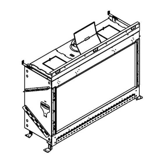
Page 7: Zero-Clearance Stand-Offs
Zero-Clearance Stand-Offs The fireplace has zero-clearance stand-offs fastened to the body of the fireplace as shown in the figures below. Stand-offs must be fully extended upon installation. Heat Shield: Attached to the top front part of the fireplace. It is foldable at the attachment site on top of the fireplace and to the top of the shield. -
Page 8: Installation
Installation NOTE: Provide the contractor with a printed copy of the “Building Checklist” on page 10 and review requirements with them. Prior to Installation Locate the Fireplace Keep the following factors in mind when selecting a location for the fireplace: Fireplace clearance requirements (review “General Clearances”... -
Page 9: Third Trip To Site: Startup
In addition, the installer must review and explain the following to the owner: Safety warnings Fireplace operation Warranty requirements Maintenance requirements Glass is hot during and after operation. If any questions or concerns arise, owner must contact the local Ortal dealer/installer for support. ... -
Page 10: Building Around The Fireplace
Building Around the Fireplace Building Checklist The following building checklist is a quick reference for a typical 60HH series fireplace installation. This list is not exhaustive and does not supplement thorough review of the installation manual. Fireplace Location: Ensure the location allows for min. 40” clearance from viewing area to furniture and other combustibles. -
Page 11: Framing
Framing Framing Requirements Fireplace chase may be framed with either combustible (typically wood studs) or non-combustible framing (typically metal studs). Any framing within 10 ” from the top of the fireplace glass (viewing area) must be non-combustible. Any framing after that point may be combustible. -
Page 12: Framing Dimensions
Framing Dimensions The following framing information applies to combustible and non-combustible framing material. The diagrams presented are for illustrative purposes only. There are multiple approved framing scenarios. A flush application is not the only permitted application. The fireplace may be recessed into the wall. Refer to diagrams and values below and in the following pages for details. 60HH Front (F) Series Fireplace Glass... - Page 13 60HH Corner (RS/LS) Series Fireplace Glass Glass Height Length Depth Stand-Off Legs Length Height 60HH " " ” ” ” ” " RS/LS Framing Fireplace 60HH RS/LS A: Height " B: Length " C: Depth ” Refer to pipe manufacturer’s V: Firestop firestop dimensions...
- Page 14 60HH Three Sided (TS) Series Fireplace Glass Glass Height Length Depth Stand-Off Legs Length Height 60HH TS " " ” ” ” ” " Framing Fireplace 60HH TS A: Height " B: Length " C: Depth ” Refer to pipe manufacturer’s V: Firestop firestop dimensions...
-
Page 15: General Clearances
General Clearances Viewing Area Clearance Zone The viewing area clearance zone is an area that extends perpendicular from the fireplace viewing area. The depth of the viewing area clearance zone depends on the combustibility of the material in question. Distance is measured from the fireplace heat barrier. Non-Combustible Materials Must be minimum 12 inches from fireplace viewing area. -
Page 16: Heat Release
Heat Release A heat release is an opening in the fireplace chase that allows the heat inside the chase to passively circulate into an interior room. This heat is generated convectively as the fireplace heats up. It is separate from exhaust heat produced in the combustion chamber of the fireplace. - Page 17 Vertical Heat Release: Split Front Vertical Heat Release: Full Side The heat release is oriented vertically and split between the two sides of the The heat release is oriented vertically. Entire chase. heat release is on one side of the fireplace chase.
-
Page 18: Air Intake Opening
Air Intake Opening An air intake opening must be incorporated into the framing and finish around the fireplace. The air intake opening is essential to maintain cool air flow between the double glass panels by allowing the double glass fans to circulate room air through the glass panels and up into the chase. - Page 19 Air Intake for a Platform NOTE: Please refer to the “Chase Floor/Platform” section on page 11 for details on platform construction.
-
Page 20: Mounting A Tv/Artwork
The decision to install a television above an Ortal fireplace is up to the discretion of the owner. TV and art manufacturers may specify that their product should not be installed on, near or above a heat source. Ortal will not be held liable for any adverse effects on a TV, artwork or other equipment located near the Ortal fireplace. - Page 21 Recessed TV/Artwork When the TV is mounted on a wall that recesses over fireplace, the TV must be at least 12 inches from the top of the fireplace glass viewing area. NOTE: Vent clearances must be maintained. See “Vent Clearances” section on page 32 for details.
-
Page 22: Access Area Requirements
Access Area Requirements Access Area Requirements for Standard 100-3 Burner For fireplaces with the Driftwood 100-3 burner, an access panel, or some other form of clear access, is required at each of the following two locations for servicing purposes: Power Vent Control Box ... -
Page 23: Chase Area Minimum
Protective Cover for Double Glass Fans Fireplaces with the double glass heat barrier come equipped with a bottom cover to protect the fans from damage. This protective cover blocks service access to gas and electrical components. The protective cover is installed under the front and sides of the fireplace. The gas and electrical components are accessible in the following locations on each model (as shown in the table below). -
Page 24: Recessed Ledge Detail
Recessed Ledge Detail A ledge over the top of a fireplace that is less than 24 inches from the top of the fireplace viewing area must maintain a minimum of 12 inches from the top of the viewing area to the top of the framing. Entire structure must be non-combustible (framing and finish). -
Page 25: Structural Weight Support
The following drawing shows a recommended approach to this type of installation. Please note that these drawings are not to scale. All fireplace drawings with correct dimensions are available on the Ortal website. -
Page 26: Step-By-Step Chase Construction
Material is not required to be non-combustible. Step 2 INSTALL FIREPLACE AND VENTING, RUN GAS AND ELECTRICAL Install the fireplace and venting. This must be completed by an authorized Ortal dealer (unless otherwise authorized by Ortal with written approval). -
Page 27: Finishing
Finishing The following diagrams show various finish applications. Diagrams apply to both combustible and non-combustible finish material. IMPORTANT NOTES: All recessed installations must comply with applicable maximum overhang limit and side wall clearances. See “Maximum Overhang/Mantel Depth” and “Clearance to a Side Wall” sections on page 15 for details. No material is permitted to extend past the metal lip surrounding the fireplace viewing area. -
Page 28: Recessed Installation
Recessed Installation Diagram applies to both combustible and non-combustible finish material. The finish must maintain at least a ” clearance to the fireplace to both the top and bottom recesses. Maximum Overhang Depth Overhang depth of a recessed fireplace must not exceed 12 inches. Overhang depth is measured from the edge of the fireplace lip to the out-most part of the wall (including finish material). -
Page 29: Venting
The Wilderness Driftwood 100-3 Firelog Burner (recommended choice for the Wilderness 60HH series) is longer than the 70-3, and it requires the fireplace to be power vented using an Ortal Power Vent. For more information on the Ortal Power Vent System, such as installation, product dimensions, and technical data, refer to the Ortal Power Vent manual. Do not use vent configuration information in the Ortal Power Vent manual. -
Page 30: Vent Configurations
IMPORTANT NOTE: A power vent is required for use with the standard a Driftwood 100-3 burner for optimal operation. For more information on the Ortal Power Vent System, refer to the Ortal Power Vent Manual. Do not use vent configuration information in the Ortal Power Vent manual for the Wilderness 60HH series fireplaces. - Page 31 IMPORTANT NOTE: A power vent is required for use with the Wilderness 60HH series fireplaces with a Driftwood 100- 3 burner for optimal operation. For more information on the Ortal Power Vent System, refer to the Ortal Power Vent Manual.
-
Page 32: Vent Restrictor Sizing Guidelines
Vent Restrictor Sizing Guidelines The restrictor sizing tables in this section determine the recommended restrictor for your vent configuration. These tables show Ortal’s recommendations only. The Environment, gas type and other factors may affect the best restrictor choice. How to use the “Recommended Restrictor” tables: Find the total vertical rise in your vent configuration along the y-axis. -
Page 33: Vent Clearances
Wilderness 60HH Series Optional: Driftwood 70-3 Burner (Passive Vent) V Minimum = 3 Feet 45’ 2.75” 42’ 2.75” 39’ 2.75” 36’ 2.75” 33’ 2.75” 1.97” 1.97” 1.97” 30’ 2.75” 1.97” 1.97” 1.97” 27’ 2.75” 1.97” 1.97” 1.97” 24’ 2.75” 2.75” 2.75”... -
Page 34: Vent Termination
Vent Termination Horizontal Termination Clearance Diagram Location Country Minimum Clearance Description Clearance above grade, veranda, porch, deck, or balcony. US & 12 inches NOTE: On private property where termination is less than 7 feet above a sidewalk, driveway, Canada deck, porch, veranda, or balcony, use of a listed cap shield is suggested. ≤... - Page 35 Covered Alcove: spaces open only on one side and with an overhang Horizontal Termination Clearances Continued: Covered Alcove Application Location Country Minimum Clearance Description Clearance under non-vinyl veranda, porch, deck, balcony, or overhang. NOTE: Termination in a covered alcove space is permitted with the dimensions specified. 1.
-
Page 36: Vertical Termination Clearance Diagram
Vertical Termination Clearance Diagram NOTE: This chart does not apply to a chimney shroud application. See the “Chimney Shroud” section on the next page for more information. TERMINATION CAP NOTE: A Low Profile Termination Cap can negatively impact flame appearance and is not recommended for use with the fireplace. -
Page 37: Chimney Shroud
Chimney Shroud Top Open Keep a minimum 6-inch clearance around the diameter of the cap’s side edge and extending above and below the cap. Sides Open Keep a minimum 6-inch clearance around the diameter of the cap’s side edge, and a minimum 10-inch clearance above the top of the cap. -
Page 38: Co-Axial To Co-Linear Conversion
failure to conform to all installation requirements will void the applicable warranty. This appliance must be properly connected to a venting system in accordance with the Ortal’s installation instructions. Operation of this appliance when not connected to a properly installed and maintained venting system can result in carbon monoxide (CO) poisoning and possibly death. -
Page 39: Vent Configuration
Vent Configuration Minimum Vertical Rise: 10 feet (see diagram below) Maximum Vertical Rise: 40 feet (see diagram below) Offsets: Two 45˚ offsets may be used directly on the fireplace with up to a 6-foot section between them. The minimum ... -
Page 40: Gas
The fireplaces are approved for use with natural gas (NG) or propane (LP) only. No other fuel types are permitted. Gas Pressures Heat Input Inlet Pressure Firelog Burner Manifold Orifice (BTU/hr) Models Gas Type Options Pressure Size Natural 650-180-500 11.0 36,101 52,000 Driftwood 100-3... -
Page 41: Gas Conversion
Firelog installation and gas conversion must be performed only by technicians who have specific authorization by Ortal to change these components. The Driftwood Firelog Kit must be supplied by Ortal. Using parts from other manufacturers or having an unauthorized party performing the conversion will void your fireplace’s warranty. Conversion instructions are supplied with the kit. -
Page 42: Gas And Electrical Components
Pilot Base Connection fitting 4mm One-piece Thermocouple NG Fitting for main line inlet to gas valve GV60 Thermocouple LPG The manufacturer of Ortal’s gas and electrical components is Mertik Maxitrol. For information on these components, please visit the manufacturer’s website: www.mertikmaxitrol.com... -
Page 43: Electrical
Electrical WARNING: Disconnect the power supply before servicing any electrical components. Electrical Requirements For both the Driftwood 100-3 and 70-3 firelog options, a duplex receptacle with two outlets (not included) must be installed in the location where the gas and electrical components will be placed, which must be to the side or back of the fireplace within 36 inches of the pilot (see “Routing the Gas Line”... -
Page 44: Wiring Diagrams
The following diagrams show the electrical wiring required for different feature combinations. For wiring diagrams with Enervex power vent, refer to the Ortal Enervex RS Power Vent System manual. For wiring diagrams with CO shutoff kit, refer to CO Shutoff Kit spec sheet at www.ortalheat.com. -
Page 45: Wiring For Optional Driftwood 70-3 Burner
Wiring for Optional Driftwood 70-3 Burner The following diagrams show the electrical wiring required for different feature combinations. For wiring diagrams with Ortal or Enervex power vent, refer to the applicable power vent manual. For wiring diagrams with CO shutoff kit, refer to CO Shutoff Kit spec sheet at www.ortalheat.com. -
Page 46: Home Automation Wiring Diagram
Wilderness Driftwood Firelogs are designed for use in the Wilderness series fireplaces only. No other interior design media options are permitted for Wilderness series fireplaces. The following Ortal firelog sets are permitted for use in the Wilderness 60HH series fireplaces. -
Page 47: Firelog Installation Warnings
Firelog Installation Warnings Firelogs are fragile. Handle them gently to prevent damage to their paint or to the fireplace. Arrange firelogs as shown the section below. Do not arrange them in any other way. If firelogs are not installed per installation instructions, flame impingement and improper combustion may occur and result in soot and/or excessive production of carbon monoxide (CO). -
Page 48: 100-3 Burner Firelog Setup
100-3 Burner Firelog Setup Log placement of the Driftwood Firelog Set is crucial for optimal fireplace operation and safety purposes. Logs must be arranged as detailed in the following pages. No other arrangement is permitted. Alternative log arrangement will affect fireplace safety, operation, and performance. - Page 49 STEP 1: Nickle Strands Use your fingers to separate the nickel strands (supplied 2x20” long) as shown in the image below. It is recommended to cut the nickel strips into 10 equal strips to make it easier to separate them. Left: Nickel strands as supplied | Right: Nickel strands ready to use Place nickel strands on top of the burner holes.
- Page 50 STEP 3 The base of log #3 can be adjusted to fit the position shown in picture above (see “Log Base Position Adjustment” section on page 56 for details). STEP 4 STEP 5 STEP 6...
- Page 51 The base of log #6 can be adjusted to fit the position shown in picture above (see “Log Base Position Adjustment” section on page 56 for details). STEP 7 The base of log #7 can be adjusted to fit the position shown in picture above (see “Log Base Position Adjustment” section on page 56 for details).
-
Page 52: 70-3 Burner Firelog Setup
70-3 Burner Firelog Setup Log placement of the Driftwood Firelog Set is crucial for optimal fireplace operation and safety purposes. Logs must be arranged as detailed in the following pages. No other arrangement is permitted. Alternative log arrangement will affect fireplace safety, operation, and performance. - Page 53 STEP 1: Nickle Strands Use your fingers to separate the nickel strands (supplied 2x20” long) as shown in the image below. It is recommended to cut the nickel strips into 10 equal strips to make it easier to separate them. Left: Nickel strands as supplied | Right: Nickel strands ready to use Place nickel strands on top of the burner holes.
- Page 54 STEP 3 STEP 4 The base of log #4 can be adjusted to fit the position shown in picture above (see “Log Base Position Adjustment” section on page 56 for details). STEP 5 The base of log #5 can be adjusted to fit the position shown in picture above (see “Log Base Position Adjustment” section on page 56 for details).
- Page 55 STEP 7 The base of log #7 can be adjusted to fit the position shown in picture above (see “Log Base Position Adjustment” section on page 56 for details). STEP 8 STEP 9 STEP 10: Charcoals (Optional) Cover the remainder of the burner with provided charcoals. Do not cover any burner holes. Maintain minimum 1-inch clearance around the pilot behind pilot hood.
-
Page 56: Log Base Position Adjustment
Log Base Position Adjustment... -
Page 57: Adjustment Instructions
Adjustment Instructions NOTE: The following images are for illustrative purposes only. Instructions apply to Front, Corner, and Three Sided models. - Page 60 Log Base Aeration...
-
Page 61: Operation
Operation WARNING – Read these instructions carefully before lighting the fireplace. Four operation options are available for use with the fireplace: 10-Button Remote Control Handset (default option, always included with the fireplace) Puck Handset (optional accessory) Wall Switch (optional accessory) ... -
Page 62: Puck Handset
Turning the Fireplace On 1. Press the button until you hear continuous beeping, and a blinking series of lines confirms the start sequence has begun; release buttons. 2. Main gas flows once pilot ignition is confirmed. 3. The system automatically goes into Manual Mode after main burner ignition. NOTE: When pilot ignition is confirmed, motor turns automatically to maximum flame height. -
Page 63: Operating Instructions
Operating Instructions Instructions for operating the Puck Handset are shown below. Turning the Fireplace On/Off Firmly press and hold the button until two short beeps confirms the start sequence has begun; release button. OFF: Firmly press the button. Increase/Decrease Flame Height INCREASE: To increase flame height, press and hold... -
Page 64: Wall Switch
Wall Switch Control Option Radio Frequency Power Supply Wall Switch IMPORTANT: For safety/communication purposes, the 10-button handset must be located within 26 feet of the receiver. Operating Instructions Turning the Fireplace On/Off ON: Press and hold the ON-OFF button until two short beeps confirms the start sequence has begun;... -
Page 65: Myfire App
To download the MyFire app, search “MyFire” at the Apple App Store or Google Play. Operating Instructions For setup and operating instructions of the MyFire app, see the Homeowner’s Fireplace Operation Manual, or visit the Ortal website or www.myfireapp.com. MyFire Wi-Fi Box The MyFire Wi-Fi router box provides the Wi-Fi connection that allows the MyFire App to operate the fireplace. -
Page 66: Fireplace Maintenance
Submerged Parts Do not use the fireplace if any part has been under water, or if you suspect that it may have been under water. The Ortal dealer service technician must inspect and, if necessary, replace any parts of the control system and any gas controls which have been under water. - Page 67 © Ortal 2022 Version 1.0, August 2022 SKU: KPMANWILD60HHV1.0 Ortal USA 2152 Citygate Drive, Columbus, OH 43219 T: (818) 238-7000 | F: (818) 678-0541 info@ortalheat.com | www.ortalheat.com...
Need help?
Do you have a question about the Wilderness 60HH Front Facing and is the answer not in the manual?
Questions and answers