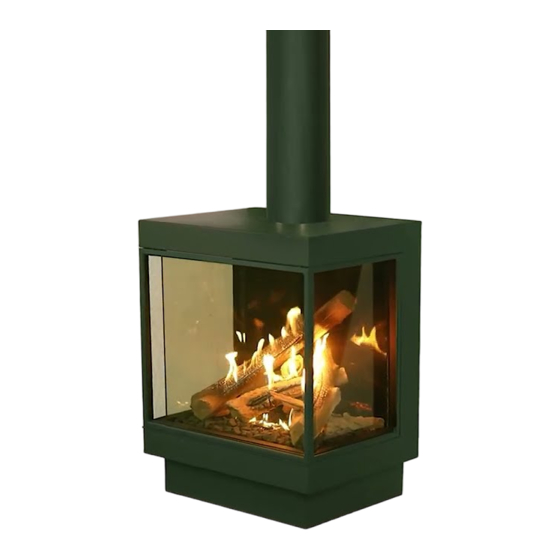
ORTAL Wilderness Stand Alone 25H TS Installation And Operation Manual
Hide thumbs
Also See for Wilderness Stand Alone 25H TS:
- Installation and operation manual (79 pages)

Related Manuals for ORTAL Wilderness Stand Alone 25H TS


Summary of Contents for ORTAL Wilderness Stand Alone 25H TS
- Page 1 Installation and Operation Manual Wilderness Stand Alone 25H TS Ortal Installation Manual: Wilderness Stand Alone 25H TS (V1.0)
-
Page 2: General
WARNING: MATERIAL USAGE All materials and objects used to carry out the installation must be certified/approved or specified by Ortal and are suitable for use. Do NOT install the system with different materials or objects than those approved for installation by Ortal. -
Page 3: Table Of Contents
Table of Contents General 2 Safety Information and Warnings Product Information Models Product Dimensions Certification Rating Label Installation 6 Prior to Installation Locate the Fireplace Floor/Platform Fireplace Installation First Trip to Site: Planning ... -
Page 4: Product Information
Driftwood 45-3 Firelogs (3 standard logs) NOTES: Venting is not supplied by Ortal with the fireplace. The fireplace is certified to be used with, and can be obtained from, the vent manufacturers outlined in “General Venting Requirements” section on page 9. -
Page 5: Certification
Certification The Wilderness Stand Alone 25H TS fireplaces have been tested and approved by CSA Group for safety and efficiency for use with Natural Gas (NG) and Propane (LP) only, and NOT for use with solid fuels. CSA Group is approved by the American National Standards Institute (ANSI) as an Accredited Standards Developer. -
Page 6: Installation
Installation Prior to Installation Locate the Fireplace Keep the following factors in mind when selecting a location for the fireplace: Fireplace clearance requirements (review “Clearances” section on page 8). Floor/platform requirements (review “Floor/Platform” section below). Adequate space for servicing. Minimum vertical vent rise, allowed horizontal lengths, and number and orientation of elbows (review “Venting”... -
Page 7: Post-Installation
In addition, the installer must review and explain the following to the owner: Safety warnings Fireplace operation Warranty requirements Maintenance requirements Glass is hot during and after operation. If any questions or concerns arise, owner must contact the local Ortal dealer/installer for support. ... -
Page 8: Clearances
Clearances Keep the following areas clear to specified materials: 1-inch clearance around the vent pipe to any material. 1-inch clearance from the back of the fireplace to any material. 4-inch clearance directly above the fireplace to any material. This does not apply to the wall behind the fireplace and ... -
Page 9: Venting
POWER VENT NOTE: Stand Alone model fireplaces are approved for power-venting with an Enervex system only. Ortal- manufactured power vents cannot be used with Stand Alone fireplaces. See Ortal’s Enervex RS Power Vent Manual for more details on power venting with an Enervex power vent. - Page 10 TERMINATION CAP NOTE: Low Profile Termination Cap and Sconce Termination Cap can negatively impact flame appearance and are not recommended for use with the fireplace. Allowable Maximum Horizontal Runs Wilderness Stand Alone 25H TS V minimum = 3 feet Vertical (V)
-
Page 11: Vent Restrictor Sizing Guidelines
Vent Restrictor Sizing Guidelines The restrictor sizing tables in this section determine the recommended restrictor for your vent configuration. These tables show Ortal’s recommendations only. The Environment, gas type and other factors may affect the best restrictor choice. How to use the “Recommended Restrictor” tables: Find the total vertical rise in your vent configuration along the y-axis. -
Page 12: Vent Termination
Vent Termination Horizontal Termination Clearance Diagram Location Country Minimum Clearance Description Clearance above grade, veranda, porch, deck, or balcony. US & 12 inches NOTE: On private property where termination is less than 7 feet above a sidewalk, driveway, Canada deck, porch, veranda, or balcony, use of a listed cap shield is suggested. ... - Page 13 Covered Alcove: spaces open only on one side and with an overhang Horizontal Termination Clearances Continued: Covered Alcove Application Location Country Minimum Clearance Description Clearance under non-vinyl veranda, porch, deck, balcony, or overhang. NOTE: Termination in a covered alcove space is permitted with the dimensions specified. 1.
-
Page 14: Vertical Termination Clearance Diagram
Vertical Termination Clearance Diagram NOTE: This chart does not apply to a chimney shroud application. See the “Chimney Shroud” section on the next page for more information. TERMINATION CAP NOTE: A Low Profile Termination Cap can negatively impact flame appearance and is not recommended for use with the fireplace. -
Page 15: Chimney Shroud
Chimney Shroud Top Open Keep a minimum 6-inch clearance around the diameter of the cap’s side edge and extending above and below the cap. Sides Open Keep a minimum 6-inch clearance around the diameter of the cap’s side edge, and a minimum 10-inch clearance above the top of the cap. -
Page 16: Gas
The fireplaces are approved for use with natural gas (NG) or propane (LP) only. No other fuel types are permitted. Gas Pressures Heat Input Inlet Pressure Manifold Orifice (BTU/hr) Fireplace Series Firelog Burner Gas Type Pressure Size* 220-130-220 Natural Gas 11.0 12,613 29,861... -
Page 17: Gas Conversion
Firelog installation and gas conversion must be performed only by technicians who have specific authorization by Ortal to change these components. The Firelog set must be supplied by Ortal. Using parts from other manufacturers or having an unauthorized party performing the conversion will void your fireplace’s warranty. -
Page 18: Decorative Skirt Removal
Decorative Skirt Removal To access the gas and electrical components, the decorative skirt attached to the bottom of the fireplace must be removed. Follow the instructions below for skirt removal and reinstallation. -
Page 21: Electrical
Electrical WARNING: Disconnect the power supply before servicing any electrical components. Electrical Requirements A duplex receptacle with two outlets (not included) must be installed on the wall no closer than 1” of the bottom of the fireplace. For aesthetic purposes, it is recommended to install the outlet on the floor directly under the fireplace. Because the fireplace is required to be plugged into an outlet, batteries MUST NOT be installed in the receiver as this could cause operation malfunctions. -
Page 22: Wiring Diagrams
Wiring Diagrams The following diagram shows the electrical wiring required for the Wilderness Stand Alone 25H TS. If the fireplace is being power vented, please refer to the applicable power vent manual for wiring information. If the fireplace has a CO Shutoff Kit, please refer to the CO Shutoff Kit spec sheet for wiring information. -
Page 23: Home Automation Wiring Diagram
The Wilderness Firelog Sets are designed for use in the Wilderness series fireplaces only. No other interior design media options are permitted for Wilderness series fireplaces. The following Firelog sets are permitted in the Wilderness Stand Alone 25H TS fireplace: Dark Brown Firelog Set, Natural Gas SKU: MLLBSMD3... -
Page 24: Firelog Installation Warnings
Firelog Installation Warnings Firelogs are fragile. Handle them gently to prevent damage to their paint or to the fireplace. Arrange firelogs as shown the section below. Do not arrange them in any other way. If firelogs are not installed per installation instructions, flame impingement and improper combustion may occur and result in soot and/or excessive production of carbon monoxide (CO). -
Page 25: Dark Brown Firelog Setup
Setup can take up to 1 hour to complete. Handle logs gently to avoid paint damage. Log placement is the same for NG and LP. The following items are included with the Dark Brown Firelog set for the Wilderness Stand Alone 25H TS. Items supplied with Dark Brown Firelog set... - Page 26 STEP 1: Nickle Strands Use your fingers to separate the nickel strands (supplied 2x20” long) as shown in the image below. It is recommended to cut the nickel strips into 10 equal strips to make it easier to separate them. Left: Nickel strands as supplied | Right: Nickel strands ready to use Place nickel strands on top of the burner holes.
- Page 27 Arrange firelogs as shown in Steps 2-12. STEP 2 STEP 3...
- Page 28 STEP 4 The base of log #4 can be adjusted to fit the position shown in pictures above (see “Log Base Position Adjustment” section on page 46 for details). STEP 5...
- Page 29 STEP 6 STEP 7 The base of log #7 can be adjusted to fit the position shown in pictures above (see “Log Base Position Adjustment” section, pg 46).
- Page 30 STEP 8 STEP 9...
- Page 31 STEP 10 The base of log #10 can be adjusted to fit the position shown in pictures above (see “Log Base Position Adjustment” section on page 46 for details). STEP 11...
- Page 32 STEP 12 STEP 13 Add charcoal pieces to the bottom of the firebox. Do not cover any burner holes. Maintain minimum 1-inch clearance around the pilot behind pilot hood. WARNING: For safety and optimal fireplace function, keep 1 inch around the pilot (behind pilot hood) completely clear of any media or debris.
-
Page 33: Chopped Wood Firelog Setup
Setup can take up to 1 hour to complete. Handle logs gently to avoid paint damage. Log placement is the same for NG and LP. The following items are included with the Chopped Wood Firelog set for the Wilderness Stand Alone 25H TS. Items supplied with Chopped Wood Firelog set... - Page 34 STEP 1: Nickle Strands Use your fingers to separate the nickel strands (supplied 2x20” long) as shown in the image below. It is recommended to cut the nickel strips into 10 equal strips to make it easier to separate them. Left: Nickel strands as supplied | Right: Nickel strands ready to use Place nickel strands on top of the burner holes.
- Page 35 Arrange firelogs as shown in Steps 2-9. STEP 2 STEP 3 The base of log #3 can be adjusted to fit the position shown in pictures above (see “Log Base Position Adjustment” section on page 46 for details).
- Page 36 STEP 4 STEP 5...
- Page 37 STEP 6 The base of log #6 can be adjusted to fit the position shown in pictures above (see “Log Base Position Adjustment” section, pg 46). STEP 7...
- Page 38 STEP 8 The base of log #8 can be adjusted to fit the position shown in pictures above (see “Log Base Position Adjustment” section, pg 46). STEP 9...
- Page 39 STEP 10 Add charcoal pieces to the bottom of the firebox. Do not cover any burner holes. Maintain minimum 1-inch clearance around the pilot behind pilot hood. WARNING: For safety and optimal fireplace function, keep 1 inch around the pilot (behind pilot hood) completely clear of any media or debris.
-
Page 40: Driftwood Firelog Setup
Setup can take up to 1 hour to complete. Handle logs gently to avoid paint damage. Log placement is the same for NG and LP. The following items are included with the Driftwood Firelog set for the Wilderness Stand Alone 25H TS. Items supplied with Driftwood Firelog set... - Page 41 STEP 1: Nickle Strands Use your fingers to separate the nickel strands (supplied 2x20” long) as shown in the image below. It is recommended to cut the nickel strips into 10 equal strips to make it easier to separate them. Left: Nickel strands as supplied | Right: Nickel strands ready to use Place nickel strands on top of the burner holes.
- Page 42 Arrange firelogs as shown in Steps 2-8. STEP 2 STEP 3 The base of log #3 can be adjusted to fit the position shown in pictures above (see “Log Base Position Adjustment” section on page 46 for details).
- Page 43 STEP 4 STEP 5 The base of log #5 can be adjusted to fit the position shown in pictures above (see “Log Base Position Adjustment” section on page 46 for details).
- Page 44 STEP 6 STEP 7...
- Page 45 STEP 8 The base of log #8 can be adjusted to fit the position shown in pictures above (see “Log Base Position Adjustment” section on page 46 for details). STEP 9 Add charcoal pieces to the bottom of the firebox. Do not cover any burner holes. Maintain minimum 1-inch clearance around the pilot behind pilot hood.
-
Page 46: Log Base Position Adjustment
Log Base Position Adjustment... -
Page 47: Adjustment Instructions
Adjustment Instructions NOTE: The following images are for illustrative purposes only. Instructions show a different model fireplace, but information applies to the Wilderness Stand Alone 25H TS. -
Page 50: Log Base Aeration
Log Base Aeration NOTE: The following images are for illustrative purposes only. Instructions show a different model fireplace, but information applies to the Wilderness Stand Alone 25H TS. - Page 51 Operation WARNING – Read these instructions carefully before lighting the fireplace. Four operation options are available for use with the fireplace: 10-Button Remote Control Handset (default option, always included with the fireplace) Puck Handset (optional accessory) Wall Switch (optional accessory) ...
- Page 52 Turning the Fireplace On 1. Press the button until you hear continuous beeping, and a blinking series of lines confirms the start sequence has begun; release buttons. 2. Main gas flows once pilot ignition is confirmed. 3. The system automatically goes into Manual Mode after main burner ignition. NOTE: When pilot ignition is confirmed, motor turns automatically to maximum flame height.
- Page 53 Operating Instructions Instructions for operating the Puck Handset are shown below. Turning the Fireplace On/Off Firmly press and hold the button until two short beeps confirms the start sequence has begun; release button. OFF: Firmly press the button. Increase/Decrease Flame Height INCREASE: To increase flame height, press and hold button.
- Page 54 Wall Switch Control Option Radio Frequency Power Supply Wall Switch IMPORTANT: For safety/communication purposes, the 10-button handset must be located within 26 feet of the receiver. Operating Instructions Turning the Fireplace On/Off ON: Press and hold the ON-OFF button until two short beeps confirms the start sequence has begun;...
- Page 55 To download the MyFire app, search “MyFire” at the Apple App Store or Google Play. Operating Instructions For setup and operating instructions of the MyFire app, see the Homeowner’s Fireplace Operation Manual, or visit the Ortal website or www.myfireapp.com. MyFire Wi-Fi Box The MyFire Wi-Fi router box provides the Wi-Fi connection that allows the MyFire App to operate the fireplace.
- Page 56 Submerged Parts Do not use the fireplace if any part has been under water, or if you suspect that it may have been under water. The Ortal dealer service technician must inspect and, if necessary, replace any parts of the control system and any gas controls which have been under water.
- Page 57 © Ortal 2022 Version 1.0, January 2022 SKU: KPMANWILDSA25HTSV1.0 Ortal USA 8421 Canoga Ave Canoga Park, CA 91304 T: (818) 238-7000 | F: (818) 678-0541 info@ortalheat.com | www.ortalheat.com ...
Need help?
Do you have a question about the Wilderness Stand Alone 25H TS and is the answer not in the manual?
Questions and answers