Table of Contents
Advertisement
Quick Links
Advertisement
Table of Contents

Related Manuals for ORTAL Stand Alone Front Series


Summary of Contents for ORTAL Stand Alone Front Series
- Page 1 Installation and Operation Manual Stand Alone Front Series Stand Alone Front Series Fireplaces: Stand Alone 75 Front (decorative base optional) Stand Alone 110 Front (decorative base optional) Stand Alone 150 Front Ortal Installation Manual: Stand Alone Front Series (V1.0)
-
Page 2: General
WARNING: MATERIAL USAGE All materials and objects used to carry out the installation must be certified/approved or specified by Ortal and are suitable for use. Do NOT install the system with different materials or objects than those approved for installation by Ortal. -
Page 3: Table Of Contents
Table of Contents “” Denotes new or changed information from most recent version manual. General 2 Safety Information and Warnings Table of Contents Product Information 4 Certification → Models General Product Information → Product Dimensions ... -
Page 4: Product Information
Product Information Certification The Stand Alone Front series fireplaces have been tested and approved by CSA Group for safety and efficiency for use with Natural Gas (NG) and Propane (LP) only, and NOT for use with solid fuels. CSA Group is approved by the American National Standards Institute (ANSI) as an Accredited Standards Developer. - Page 5 General Product Features Decorative Base (optional add-on)
-
Page 6: General Product Information 4 → Product Dimensions
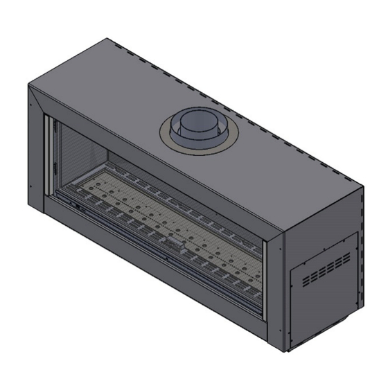
→ Product Dimensions Stand Alone 75 Front Approximate Weight: 172 lbs... - Page 7 Hanging Bracket Stand Alone 75 Front with Decorative Base NOTE: The decorative base is an optional add-on feature available for the Stand Alone 75 Front and Stand Alone 110 Front. It allows the fireplace to be mounted to the base instead of a wall.
- Page 8 Stand Alone 110 Front Approximate Weight: 231 lbs...
- Page 9 Hanging Bracket Stand Alone 110 Front with Decorative Base NOTE: The decorative base is an optional add-on feature available for the Stand Alone 75 Front and Stand Alone 110 Front. It allows the fireplace to be mounted to the base instead of a wall.
- Page 10 Stand Alone 150 Front Approximate Weight: 282 lbs...
- Page 11 Hanging Bracket NOTE: The decorative base is not available for the Stand Alone 150 Front.
-
Page 12: Rating Label
Rating Label The fireplace rating label is found on a metal plate separate included with the fireplace. DEALERS/INSTALLERS: You MUST leave the fireplace’s rating label with the fireplace in an area easily accessible by the owner (typically near the access panel, if available). -
Page 13: Installation
On a wall (see “Wall-Mounting Instructions” section on page 14 for details). On the Ortal decorative base (see “Base-Mounting Instructions” section on page 22 for details). If fireplace is wall-mounted, remove shipping legs after installation. Install the vent components. See “Vent Installation” section on page 41 ... -
Page 14: Wall-Mounting Instructions
→ Wall-Mounting Instructions The following sections explain how to mount the fireplace on either (1) wood-framed walls or (2) concrete/masonry walls. The diagrams in these sections are for illustration purposes only and apply to all models covered in this manual. For clearances, see “Wall-Mounted Fireplace Clearances”... - Page 15 Locate the Hanging Bracket: Using the dimensions in the table and diagram below, measure down from the center top your non-combustible zone. This is the center line for the bolts for the hanging bracket. X Measurement: Stand Alone 75 Front: X = 13 "...
- Page 16 Fill in Non-Combustible Zone: Fill and secure the entire non-combustible zone with " cement board, fireplace construction board (e.g., Promat Promafour), or its equivalent, matching the thickness of the surrounding wall. This board will likely need to be oversized so it can be attached to framing studs. Dimension will very per project. Drywall (including ”...
- Page 17 Mount the Hanging Bracket: Center the hanging bracket along the line marking you just made. Using the information in the table below, mount the bracket to the wall using the four "-diameter lag bolts following the bolt manufacturer's requirements (bolts are not provided). Recommended bolt length is minimum 3” but may need to be longer depending on project design needs.
- Page 18 Step 5: Mount the Fireplace to the Wall Recommended – Make a Vertical Mark on the Wall: Find the center of the top of the hanging bracket and make a vertical mark at a 90º angle to the hanging bracket. This will be used as a guide to center the fireplace while attaching it to the hanging bracket.
- Page 19 Concrete or Masonry Wall You will need to provide: Four " diameter extension bolts (recommended bolt length is minimum 3” but may need to be longer depending on project design needs) NOTE: This section assumes the non-combustible finish is already in place. Step 1: Mark the desired location of the fireplace on the wall.
- Page 20 Step 3: Mark the location of the gas line and electrical outlet on the wall. Find the Gas and Electrical Locations on the Wall: Route the gas line and outlet to the bottom right of the fireplace (in reference to a front view of the fireplace) using the hanging bracket marking made in Step 2. Refer to the diagram below for measurements.
- Page 21 Step 4: Mount the Fireplace to the Wall Recommended – Make a Vertical Mark on the Wall: Find the center of the hanging bracket and make a vertical mark at a 90º angle to the hanging bracket. This will be used as a guide to center the fireplace while attaching it to the hanging bracket. The mark will need to extend high enough to be seen while hanging the fireplace to the wall.
-
Page 22: Base-Mounting Instructions
Base-Mounting Instructions This section explains how to attach the fireplace to the Ortal Decorative Base. The fireplace does not need to be mounted to a wall if it is attached to this base. The base fully supports the entire weight of the fireplace. -
Page 29: Third Trip To Site: Startup
In addition, the installer must review and explain the following to the owner: Safety warnings Fireplace operation Warranty requirements Maintenance requirements Glass is hot during and after operation. If any questions or concerns arise, owner must contact the local Ortal dealer/installer for support. ... -
Page 30: Clearances
→ Clearances Wall-Mounted Fireplace Clearances Keep the following areas clear to specified materials: 1-inch clearance around the vent pipe to any material. 12-inch clearance directly above the fireplace to any material. This does not apply to the wall behind the fireplace and ... -
Page 31: Base-Mounted Fireplace Clearances
Base-Mounted Fireplace Clearances Keep the following areas clear to specified materials: 1-inch clearance around the vent pipe to any material. 1-inch clearance from the back of the fireplace to any material. 4-inch clearance directly above the fireplace to any material. This does not apply to the wall behind the fireplace and ... -
Page 32: Decorative Skirt Installation
Decorative Skirt Installation NOTE: To remove the skirt, perform the steps below in reverse order. -
Page 33: Venting
POWER VENT NOTE: Stand Alone model fireplaces are approved for power-venting with an Enervex system only. Ortal- manufactured power vents cannot be used with Stand Alone fireplaces. See Ortal’s Enervex RS Power Vent Manual for more details on power venting with an Enervex power vent. -
Page 34: Vent Configurations
The following sections provide information for calculating vent configuration distances and elbows. For vent configurations that cannot conform to these guidelines, consider the Enervex RS Power Vent System, or contact Ortal for assistance. Power Vent information can be found in the Ortal Enervex RS Power Vent System Manual. -
Page 35: Maximum Allowable Horizontal Runs
TERMINATION CAP NOTE: Low Profile Termination Cap and Sconce Termination Cap can negatively impact flame appearance and are not recommended for use with the fireplace. Maximum Allowable Horizontal Runs Stand Alone 75 Front Stand Alone 110 Front Stand Alone 150 Front V minimum = 0 feet V minimum = 3 feet V minimum = 3 feet... -
Page 36: Vent Restrictors
Vent Restrictors The restrictor sizing tables in this section determine the recommended restrictor for your vent configuration. These tables show Ortal’s recommendations only. The environment, gas type, and other factors may affect the best restrictor choice. How to use the “Recommended Restrictor” tables: Find the total vertical rise in your vent configuration along the y-axis. -
Page 37: Vent Clearances
Stand Alone 150 Front V Minimum = 3 Feet 44’ 2.75” 33’ 2.75” 2.75” 2.75” 1.97” 30’ 2.75” 2.75” 2.75” 1.97” 27’ 2.75” 2.75” 2.75” 1.97” 24’ 2.75” 2.75” 2.75” 1.97” 1.57” 21’ 2.75” 2.75” 1.97” 1.57” 1.57” 1.18” 1.18” 18’... -
Page 38: Vent Termination
Vent Termination Horizontal Termination Clearances Location Country Minimum Clearance Description Clearance above grade, veranda, porch, deck, or balcony. US & 12 inches NOTE: On private property where termination is less than 7 feet above a sidewalk, driveway, Canada deck, porch, veranda, or balcony, use of a listed cap shield is suggested. ... - Page 39 Covered Alcove: spaces open only on one side and with an overhang Horizontal Termination Clearances Continued: Covered Alcove Application Location Country Minimum Clearance Description Clearance under non-vinyl veranda, porch, deck, balcony, or overhang. NOTE: Termination in a covered alcove space is permitted with the dimensions specified. 1.
- Page 40 Vertical Termination Clearances NOTE: This chart does not apply to a chimney shroud application. See the “Chimney Shroud” section on the next page for more information. TERMINATION CAP NOTE: A Low Profile Termination Cap can negatively impact flame appearance and is not recommended for use with the fireplace.
-
Page 41: Chimney Shroud
Chimney Shroud Top Open Keep a minimum 6-inch clearance around the diameter of the cap’s side edge and extending above and below the cap. Sides Open Keep a minimum 6-inch clearance around the diameter of the cap’s side edge, and a minimum 10-inch clearance above the top of the cap. -
Page 42: Gas
The fireplaces are approved for use with natural gas (NG) or propane (LP) only. No other fuel types are permitted. Gas Pressures Heat Input Inlet Pressure Manifold Orifice (BTU/hr) Fireplace Series Burner Gas Type Pressure Size* Natural Gas 10.0 16,147 29,100 Stand Alone 75 Front 45 Single... -
Page 43: Gas Conversion
Gas conversion (NG to LP or LP to NG) of the Stand Alone series fireplaces can be done in the field. Gas conversion must only be performed by a technician who has specific authorization by Ortal to change these components. The conversion kit must be supplied by Ortal. -
Page 44: Electrical
WARNING: Disconnect the power supply before servicing any electrical components. Electrical Requirements The Stand Alone Front series fireplaces have the option to either run on 4 AA batteries or a 6-Volt AC Adapter. The AC Adapter is provided with the fireplace. Batteries are not included. -
Page 45: Power Outage
A = Distance from Center Line of Bracket Bolt Holes to the gas knockout. B = Distance from bottom of the gas knockout to the start of the electrical outlet (optional). C = Distance from the vertical centerline of the fireplace to the gas knockout. D = Distance from the vertical centerline of the fireplace to the electrical outlet (optional). -
Page 46: Pairing The Remote And Receiver
Pairing the Remote and Receiver To set up the remote-control device to operate the fireplace, follow the following guidelines to pair the remote and receiver unit on the same radio frequency. Press and hold the receiver’s reset button until you hear two beeps. The first beep is short, and the second beep is long. - Page 47 Wiring Diagram: Screen Fireplace (AC Adapter)
- Page 48 Home Automation Wiring Diagram Use the following wiring diagram to connect fireplace control a hardwired home automation system. Contacts Options/Operation Ignition: Close contacts 0 (orange) and 2 (brown) simultaneously for 1 second. Fireplace automatically goes to high after ignition. Up Flame: Close contacts 0 (orange) and 1 (red) simultaneously. The contact needs to be closed for 12 seconds to turn the motor from end-stop to end-stop.
-
Page 49: Interior Design Media
Interior Design Media Media Placement Guidelines When installing media, adhere to the following general guidelines: Keep the media back from the pilot hood so at least one burner port is open. Crowding around the pilot hood may hinder lighting and could result in potential damage to the fireplace and surrounding area or personal injury. Do not use the hood to support media. - Page 50 Log Media Placement Place the logs carefully to block as few ports as possible. If a log is placed over a port, block the port with a “coin” to keep the flame from creating soot on the media or to manipulate the look of the flame. COINS Block as few ports as possible, and no more than 30% of total ports.
- Page 51 Operation WARNING – Read these instructions carefully before lighting the fireplace. Four operation options are available for use with the fireplace: 10-Button Remote Control Handset (default option, always included with the fireplace) Puck Handset (optional accessory) Wall Switch (optional accessory) ...
- Page 52 Turning the Fireplace On 1. Press the button until you hear continuous beeping, and a blinking series of lines confirms the start sequence has begun; release buttons. 2. Main gas flows once pilot ignition is confirmed. 3. The system automatically goes into Manual Mode after main burner ignition. NOTE: When pilot ignition is confirmed, motor turns automatically to maximum flame height.
- Page 53 Operating Instructions Instructions for operating the Puck Handset are shown below. Turning the Fireplace On/Off Firmly press and hold the button until two short beeps confirms the start sequence has begun; release button. OFF: Firmly press the button. Increase/Decrease Flame Height INCREASE: To increase flame height, press and hold...
- Page 54 Wall Switch Control Option Radio Frequency Power Supply Wall Switch IMPORTANT: For safety/communication purposes, the 10-button handset must be located within 26 feet of the receiver. Operating Instructions Turning the Fireplace On/Off ON: Press and hold the ON-OFF button until two short beeps confirms the start sequence has begun;...
- Page 55 To download the MyFire app, search “MyFire” at the Apple App Store or Google Play. Operating Instructions For setup and operating instructions of the MyFire app, see the Homeowner’s Fireplace Operation Manual, or visit the Ortal website or www.myfireapp.com. MyFire Wi-Fi Box The MyFire Wi-Fi router box provides the Wi-Fi connection that allows the MyFire App to operate the fireplace.
- Page 56 Submerged Parts Do not use the fireplace if any part has been under water, or if you suspect that it may have been under water. The Ortal dealer service technician must inspect and, if necessary, replace any parts of the control system and any gas controls which have been under water.
- Page 57 © Ortal 2022 Version 1.0, July 2022 SKU: KPMANSAFV1.0 Ortal USA 8421 Canoga Ave Canoga Park, CA 91304 T: (818) 238-7000 | F: (818) 678-0541 info@ortalheat.com | www.ortalheat.com ...
Need help?
Do you have a question about the Stand Alone Front Series and is the answer not in the manual?
Questions and answers