Table of Contents
Advertisement
Quick Links
Advertisement
Table of Contents

Related Manuals for ORTAL Wilderness Traditional Insert Series


Summary of Contents for ORTAL Wilderness Traditional Insert Series
- Page 1 Installation and Operation Manual Wilderness Traditional Insert Series Wilderness Traditional Insert Series Fireplaces: Wilderness Traditional Insert 29 Wilderness Traditional Insert 34 Ortal Installation Manual: Wilderness Traditional Insert Series (V2.0)
-
Page 2: General
WARNING: MATERIAL USAGE All materials and objects used to carry out the installation must be certified/approved or specified by Ortal and are suitable for use. Do NOT install the system with different materials or objects than those approved for installation by Ortal. -
Page 3: Table Of Contents
Table of Contents “→” Denotes new or changed information from most recent version manual. General Safety Information and Warnings Table of Contents Product Information Certification Models General Product Information Rating Label Installation Preparation Prior to Installation Locate the Fireplace Fireplace Installation Planning Installation Vent Installation... -
Page 4: Product Information
45 Single 4”x3” Traditional Insert Canada: CSA 2.33-2019 Propane NOTE: Venting is not supplied by Ortal with the fireplace. The fireplace is certified to be used with, and can be obtained from, the vent manufacturers outlined in “General Venting Requirements” section. -
Page 5: General Product Information
General Product Information The Wilderness Traditional Insert series requires; interior panel options (Brick options, Black Reflective Panels or Black Ridge Panels), a firelog set (Dark Brown or Chopped Wood), a surround and screened front to complete the installation. If any of these components are not present, please contact your authorized Ortal dealer. -
Page 6: Rating Label
Rating Label The fireplace rating label is found on a metal plate separate included with the fireplace. DEALERS/INSTALLERS: You MUST leave the fireplace’s rating label with the fireplace in an area easily accessible by the owner (typically near the access panel, if available). -
Page 7: Installation Preparation
Installation Preparation Prior to Installation Locate the Fireplace Keep the following factors in mind prior to installation in a masonry: Thoroughly clean the existing masonry chimney Properly inspect the chimney- if necessary, have repairs made by qualified personnel Ensure the masonry is constructed of non-combustible materials ... -
Page 8: Startup
In addition, the installer must review and explain the following to the owner: Safety warnings Fireplace operation Warranty requirements Maintenance requirements Glass is hot during and after operation. If any questions or concerns arise, owner must contact the local Ortal dealer/installer for support. ... -
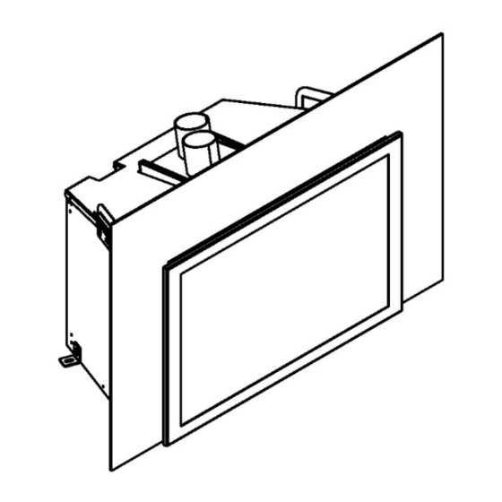
Page 9: Fireplace Requirements And Clearances
Fireplace Requirements and Clearances Fireplace Dimensions The following diagram depicts the physical fireplace dimensions. Use for reference only. For additional information on Minimum Fireplace Opening see the section on the next page. Wilderness Traditional Insert Dimensions Viewing Area Viewing Area Model Fresh Air Exhaust... -
Page 10: Minimum Fireplace Opening
Minimum Fireplace Opening This appliance must be recessed into a vented non-combustible wood-burning appliance masonry only. The minimum appliance opening size in which the appliance is to be installed is shown in the diagram below. Wilderness Traditional Insert Dimension Dimension Dimension Dimension Dimension... -
Page 11: General Clearances
General Clearances Viewing Area Clearance Zone The viewing area clearance zone is an area that extends perpendicular from the fireplace viewing area. The depth of the viewing area clearance zone depends on the combustibility of the material in question. Distance is measured from the fireplace heat barrier. Must be a minimum of 12 inches from fireplace viewing Non-Combustible Materials Must be a minimum of 16 inches from fireplace viewing... - Page 12 For combustible mantel depth greater than 16 ½”, a non-combustible floor or hearth must extend 10” from the unit. Non-Combustible flooring or hearth must remain below the bottom of the surround. A mantel is required to be a minimum of 13” from the top of the front frame.
-
Page 13: Chase Floor/Platform
Chase Floor/Platform The fireplace must be installed on a flat, solid, continuous surface. Surface can be concrete, metal, and other non-combustible floor types. Combustible flooring underneath the appliance is acceptable with a ¼” minimum gap, by utilizing the leveling legs. Raised Platform Option: To raise the fireplace higher, build a platform for the fireplace to stand on. - Page 14 Using a Phillips head screwdriver, turn the 4 leveling bolts counterclockwise to the desired height. Leg Height Adjustment #2 Using a 3mm Allen Wrench, turn the front 2 leveling bolts counterclockwise to the desired height. Both left and right sides of the insert have panels located towards the back. Remove 2 bolts for each side panel to remove ...
-
Page 15: Venting
Venting General Venting Requirements The fireplace operates using a direct vent system and requires co-linear vent pipe. The fireplace must be properly connected to an approved vent system. Venting is not provided with the fireplace and must be sourced from one of the approved vent manufacturers mentioned in the table below. -
Page 16: Connecting The Co-Linear Vent Pipe
Connecting the Co-Linear Vent Pipe WARNING: Use only stainless-steel band (hose) clamps to fix the chimney. Do NOT use self-tapping screws. Guide the 4”x3” or 3”x3” flexible liners down through the chimney. Secure the 3” liner on the fresh air intake collar on the slide plate with the hose clamp using a 5/16” nut driver. ... -
Page 17: Chimney Surround
Chimney Surround Top Open Keep a minimum 6-inch clearance around the diameter of the cap’s side edge and extending above and below the cap. Sides Open Keep a minimum 6-inch clearance around the diameter of the cap’s side edge, and a minimum 10-inch clearance above the top of the cap. -
Page 18: Gas Information
Gas Conversion Gas conversion (NG to LP or LP to NG) of the Wilderness Traditional Insert series fireplaces can be done in the field. Gas conversion must only be performed by a technician who has specific authorization by Ortal to change these components. The conversion kit must be supplied by Ortal. -
Page 19: Gas And Electrical Components
Pilot Base Connection fitting 4mm One-piece Thermocouple NG Fitting for main line inlet to gas valve GV60 Thermocouple LPG The manufacturer of Ortal’s gas and electrical components is Mertik Maxitrol. For information on these components, please visit the manufacturer’s website: www.mertikmaxitrol.com... -
Page 20: Electrical
Electrical WARNING: Disconnect the power supply before servicing any electrical components. Electrical Requirements A duplex receptacle with two outlets (not included) must be installed in the location where the gas and electrical components will be placed, which must be to the side or back of the fireplace within 36 inches of the pilot (see diagram in “Routing the Gas Line” section). Electrical work should be performed by a qualified licensed electrician, according to local code. -
Page 21: Pairing The Remote And Receiver
Pairing the Remote and Receiver To set up the remote-control device to operate the fireplace, follow the following guidelines to pair the remote and receiver unit on the same radio frequency. Press and hold the receiver’s reset button until you hear two beeps. The first beep is short, and the second beep is long. - Page 22 Home Automation Wiring Diagram Use the following wiring diagram to connect fireplace control a hardwired home automation system. Contacts Options/Operation Ignition: Close contacts 0 (orange) and 2 (brown) simultaneously for 1 second. The fireplace automatically goes to high after ignition. Up Flame: Close contacts 0 (orange) and 1 (red) simultaneously.
- Page 23 Firelog Set Up Firelog Installation Warnings Firelogs are fragile. Handle them gently to prevent damage to their paint or to the fireplace. Arrange firelogs as shown in the section below. Do not arrange them in any other way. If firelogs are not installed per installation instructions, flame impingement and improper combustion may occur and result in soot and/or excessive production of carbon monoxide (CO).
- Page 24 For Dark Brown and Chopped Wood Log and Media Set up Instructions, please refer to the add on manual included with the log set.
- Page 25 Log Base Position Adjustment Adjustment Instructions STEP 1 Remove the front frame and glass assembly. STEP 2 Pull log up to remove from the base. STEP 3 Pull up on the left grill cover to remove. Repeat step with middle and right grill covers. STEP 4 With a Phillips head screwdriver, loosen the screw holding the log base into place.
- Page 26 Log Base Aeration STEP 1 Loosen the log base aeration screw with a 2.5mm Allen Key. STEP 2 To adjust the aeration level, rotate the air shutter per specifications listed in the table below. Tighten the screw to keep the shutter in the desired position.
- Page 27 Interior Design Media Panel Option Installation Guidelines Internal panels are required to complete installation of the Wilderness Traditional Insert. Brick and Blackridge Panels Layout the three panels, ensuring that any grout lines align. Horizontal and Herringbone options back panel orientation matters for proper alignment.
- Page 28 STEP 1 Locate the support brackets from the top of the inner firebox. Using a Phillips head screwdriver, remove both brackets by removing the two bolts holding them in place. STEP 2 Locate the side vermiculite pieces (items #1 & 3) and the side brackets (items #4 & 5). The purpose of these brackets is to cover the front edges of the vermiculite (an A surface), so when installed the black bracket is visible versus the vermiculite.
- Page 29 Service Front Frame A front frame is required to complete installation of the Wilderness Traditional Insert. To remove the front frame, grasp the frame from the sides and lift upward and pull out like shown in the illustrations below. To reinstall the front frame, align the four brackets (two on each side) of the frame with the two top and two bottom bolts, lift up slightly and push decorative front toward fireplace until brackets and bolts are engaged.
- Page 30 With one hand supporting the glass assembly, locate the two keyholes located at the top of the firebox. Engage the end of the glass tool with the keyholes one at a time. Pull out and then lift to release the keyhole latches. These keyholes are spring loaded and will retract into place once released. Tilt the glass assembly forward, and then lift up and out.
- Page 31 Front Profile At the bottom of the unit there is a front profile piece which acts as a vanity panel. For proper installation, verify the side with the notch circled below is facing the unit. Part is to be installed with the glass assembly installed but prior to the front frame installation. Service Door for Electronics and Gas There are two ways to access the electrical and gas components;...
- Page 32 Slide Plate When connecting the vent liners or needing to access the insert from the external access panel follow these instructions. Locate the slide plate tool, stored on top of the insert, resting on a cut out for positive placement. Using a Phillips head screwdriver, remove the two bolts attaching the slide plate.
- Page 33 Operation WARNING – Read these instructions carefully before lighting the fireplace. Four operation options are available for use with the fireplace: 10-Button Remote Control Handset (default option, always included with the fireplace) Puck Handset (optional accessory) Wall Switch (optional accessory) ...
- Page 34 Turning the Fireplace On 1. Press the button until you hear continuous beeping, and a blinking series of lines confirms the start sequence has begun; release buttons. 2. Main gas flows once pilot ignition is confirmed. 3. The system automatically goes into Manual Mode after main burner ignition. NOTE: When pilot ignition is confirmed, motor turns automatically to maximum flame height.
- Page 35 Operating Instructions Instructions for operating the Puck Handset are shown below. Turning the Fireplace On/Off Firmly press and hold the button until two short beeps confirms the start sequence has begun; release button. OFF: Firmly press the button. Increase/Decrease Flame Height INCREASE: To increase flame height, press and hold...
- Page 36 Wall Switch Control Option Radio Frequency Power Supply Wall Switch IMPORTANT: For safety/communication purposes, the 10-button handset must be located within 26 feet of the receiver. Operating Instructions Turning the Fireplace On/Off ON: Press and hold the ON-OFF button until two short beeps confirms the start sequence has begun;...
- Page 37 To download the MyFire app, search “MyFire” at the Apple App Store or Google Play. Operating Instructions For setup and operating instructions of the MyFire app, see the Homeowner’s Fireplace Operation Manual, or visit the Ortal website or www.myfireapp.com. MyFire Wi-Fi Box The MyFire Wi-Fi router box provides the Wi-Fi connection that allows the MyFire App to operate the fireplace.
- Page 38 Submerged Parts Do not use the fireplace if any part has been under water, or if you suspect that it may have been under water. The Ortal dealer service technician must inspect and, if necessary, replace any parts of the control system and any gas controls which have been underwater.
- Page 39 © Ortal 2023 Version 2.0, April 2023 SKU: KPMANWILDTRINV2.0 Ortal USA 2152 Citygate Drive, Columbus, OH 43219 T: (818) 238-7000 | F: (818) 678-0541 info@ortalheat.com | www.ortalheat.com...
Need help?
Do you have a question about the Wilderness Traditional Insert Series and is the answer not in the manual?
Questions and answers