Advertisement
Quick Links
ENGINEER´S AND ILLUSTRATED PARTS MANUAL
WARTUNGSANLEITUNG UND ILLUSTRIERTES TEILEVERZEICHNIS
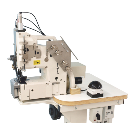
HIGH-SPEED BAG MAKING MACHINES BM/BML213CD
HOCHLEISTUNGS-SACKNÄHMASCHINEN BM/BML213CD
MANUAL NO. / KATALOG NR.
FOR STYLES / FÜR TYPEN
07/2023
ORIGINAL INSTRUCTIONS
ORIGINALBETRIEBSANLEITUNG
BM213CD1HLU
: CAT-BM-BML213CD-EN-DE
: BM213CD2, BM213CD1HLU,
BML213CD2
Advertisement
Chapters

Related Manuals for UnionSpecial BML213CD


Summary of Contents for UnionSpecial BML213CD
- Page 1 ORIGINAL INSTRUCTIONS ENGINEER´S AND ILLUSTRATED PARTS MANUAL ORIGINALBETRIEBSANLEITUNG WARTUNGSANLEITUNG UND ILLUSTRIERTES TEILEVERZEICHNIS BM213CD1HLU HIGH-SPEED BAG MAKING MACHINES BM/BML213CD HOCHLEISTUNGS-SACKNÄHMASCHINEN BM/BML213CD MANUAL NO. / KATALOG NR. : CAT-BM-BML213CD-EN-DE FOR STYLES / FÜR TYPEN : BM213CD2, BM213CD1HLU, BML213CD2 07/2023...
-
Page 3: Preface
MANUAL NO. CAT-BM-BML213CD-EN-DE KATALOG NR. CAT-BM-BML213CD-EN-DE INSTRUCTIONS FOR BETRIEBSANLEITUNG FÜR BM/BML213CD Bag-Making Machines BM/BML213CD Sacknähmaschinen First Edition ©2023 Erste Auflage ©2023 Union Special GmbH Rights reserved in all Countries Weltweit beanspruchte Union Special GmbH Rechte PREFACE VORWORT This manual assists you in the operation and mainte- Diese Betriebsanleitung leitet Sie bei der Bedienung nance of your machine and simplifies spares orders. -
Page 4: Safety Rules
SAFETY RULES SICHERHEITSHINWEISE Before putting the machine described in Lesen Sie vor Inbetriebnahme der in diesem this manual into service, carefully read the Katalog beschriebenen Maschine die Betriebs- instructions. Starting up your machine is only anleitung sorgfältig durch. Jede Maschine permitted after taking note of the instructions darf erst nach Kenntnisnahme der Betriebs- and by qualified operators. - Page 5 8.2. While replacing any parts such as needle(s), 8.2. Zum Auswechseln von Nähwerkzeugen wie presser foot, throat plate, looper, spreader, Nadel, Drückerfuß, Stichplatte, Greifer, Le- feed dog, needle guard, folder, fabric guide ger, Transporteur, Nadelanschlag, Apparat, etc. Nähgutführung usw. 8.3. When leaving the workplace and during unat- 8.3.
-
Page 7: Table Of Contents
TABLE OF CONTENTS INHALTSVERZEICHNIS Preface ..............3 Vorwort ..............3 Safety Rules ............4 Sicherheitshinweise ..........4 Machine description..........8 Maschinenbeschreibung.......... 8 Operating Instructions ........... 12 Bedienungsanleitung ..........12 Cleaning ..............12 Reinigung .............. 12 Caution Areas ............13 Gefährdungszonen ..........13 Inserting Needles........... -
Page 8: Machine Description
MACHINE DESCRIPTION MASCHINENBESCHREIBUNG Machine Style BM213CD2 Maschinentype BM213CD2 High performance bag sewing machine for matched Hochleistungs-Sacknähmaschinen für das seams on extremely heavy container bags (FIBCs) verschiebungsfreie Nähen von extra schweren Con- made of polypropylene fabric. tainersäcken (FIBCs) aus Polypropylengewebe. Easy crossing of side seams and belts. Müheloses Überqueren von Seitennähten und Gurt- bändern möglich. - Page 9 Machine Style BM213CD1HLU Maschinentype BM213CD1HLU High performance bag sewing machine for matched Hochleistungs-Sacknähmaschinen für das seams on extremely heavy container bags (FIBCs) verschiebungsfreie Nähen von extra schweren Con- made of polypropylene fabric. tainersäcken (FIBCs) aus Polypropylengewebe. Easy crossing of side seams and belts. Müheloses Überqueren von Seitennähten und Gurt- bändern möglich.
- Page 10 Machine Style BML213CD2 Maschinentype BML213CD2 High performance bag-seaming longarmmachine Hochleistungs-Langarm-Sacknähmaschine mit with geared belt drive for matched bag seams and Zahnriemenantrieb zum verschiebungsfreien Nähen similar material. Especially for sewing Q-bags made von Säcken und ähnlichem Nähgut. of polypropylene fabric. Speziell zum Nähen von Q-Bags (Wabensäcken) aus Polypropylengewebe.
-
Page 12: Operating Instructions
OPERATING INSTRUCTIONS BEDIENUNGSANLEITUNG Starting up the machine Inbetriebnahme Prior to leaving our factory each machine is carefully Vor Verlassen unseres Werks wurde jede Maschine inspected, adjusted and given a function test. How- sorgfältig geprüft, eingestellt und ein Funktionstest ever, upon receipt the machine should be inspected durchgeführt. -
Page 13: Caution Areas
CAUTION AREAS GEFÄHRDUNGSZONEN ACHTUNG! Tragen Sie eine Schutzbrille. Nicht ohne Schutz- einrichtungen ACHTUNG! arbeiten, Nicht ohne Verletzungsgefahr Riemenschutz arbeiten! ACHTUNG! Deckel muß während des Nähens geschlossen sein... -
Page 14: Inserting Needles
INSERTING NEEDLES EINSETZEN DER NADELN The standard needle is 9848GF300/120. Insert nee- Die Standardnadel ist 9848GF300/120. Setzen Sie dles according to the following procedure: die Nadel wie folgt ein: 1. Bring the needle head (A) to the highest 1. Bringen Sie den Nadelkopf (A) in die obere position. -
Page 15: Threading The Machine
THREADING THE MACHINE EINFÄDELN DER MASCHINE Turn off main power supply before Schalten Sie vor dem Einfädeln threading! When using clutch den Hauptschalter aus! Beim motors without actuation lock Gebrauch von Kupplungsmotoren wait until motor has completely ohne Betätigungssperre ist der stopped. -
Page 17: Oil Specification Requirements
OIL SPECIFICATION REQUIREMENTS ERFORDERLICHE ÖL-SPEZIFIKATION All oils shall be non compounded, straight miner- Sämtliche Öle sollten ungebundene, pure Mine- al oils, of high viscosity index (will not thin down ralöle mit hoher Viscosität sein (verdünnen sich excessively with heat). Practically all oil compa- bei Hitze nicht übermäßig). -
Page 18: Lubrication
LUBRICATION ÖLEN CAUTION! Oil has been drained from the machine ACHTUNG: Vor dem Versand wurde das Öl aus before shipping and the reservoir must be filled der Maschine abgelassen, der Ölbehälter muß des- before starting operation. Use the oil with UNION halb vor der Inbetriebnahme gefüllt werden. - Page 19 NOTE: If the oil pressure gauge (D) does not BEACHTEN SIE: Falls während des Betriebs show any oil pressure during operation, shut off kein Öldruck am Öldruckschauglas (D) an- the machine and check the oil lines to make sure gezeigt wird, schalten Sie die Maschine aus, they do not show a sharp bend reducing oil flow und prüfen die Ölleitungen, um sicher zu or an obstruction in the oil line or oil siphon fil-...
-
Page 20: Oil Flow Diagram
OIL FLOW DIAGRAM ÖLFLUSS-DIAGRAMM The oiling system distributes pressurized oil 4-15 Die Druckschmierung leitet das Öl mit 0,3 - 1 bar PSI (0.3 - 1 bar) through an oil distributor (A) to über einen Druckverteiler (A) an vier Lagerstellen four bearings (B), (E), (C), (D). From there the oil is (B), (E), (C), (D). -
Page 22: Maintenance Plan Bm/Bml213
MAINTENANCE PLAN BM/BML213 WARTUNGSPLAN BM/BML213 On a daily basis at the beginning of shift work Täglich bei Schichtbeginn 1. Check oil level at oil gauge glass after clos- 1. Ölspiegel im Ölschauglas nach 30 bis 40 ing 30 to 40 bags. Säcken kontrollieren. -
Page 23: Adjusting The Stitch Length
ADJUSTING THE STITCH LENGTH STICHLÄNGEN-EINSTELLUNG 1. Remove plug (A). 1. Entfernen Sie die Schraube (A). 2. Turn handwheel until center adjustment 2. Drehen Sie die Riemenscheibe bis die Ein- screw (B) is visible. stellschraube (B) mittig sichtbar wird. 3. Turn adjustment screw (B) clockwise to 3. -
Page 24: Feed Dog Setting
FEED DOG SETTING TRANSPORTEUR-EINSTELLUNG Set the height of the feed dog into its highest Stellen Sie die Höhe des Transporteurs in position so that the rear teeth protrude .060” seiner höchsten Stellung so ein, dass die (1.5mm) above the throat plate surface. Tilt hinteren Zähne 1,5 mm aus der Stichplatte front of the feed dog to its highest position when ragen. -
Page 25: Aligning The Needle Bar
ALIGNING THE NEEDLE BAR AUSRICHTEN DER NADELSTANGE Align the needles so both needles penetrate the Richten Sie die Nadelstange so aus, dass needle holes in the throat plate in the middle beide Nadeln mittig in die Stichlöcher in der (Fig. 2). Stichplatte einstechen (Fig. -
Page 26: Looper Setting
LOOPER SETTING GREIFER-EINSTELLUNG Set the left looper point to 7mm from the tip of In der rechten Endposition der Greifer stellen the left needle when the loopers are at their Sie die vordere Greiferspitze 7 mm zur linken right end position. For setting loosen screw in Nadelspitze ein. -
Page 27: Needle Guard Setting
NEEDLE GUARD SETTING NADELANSCHLAG-EINSTELLUNG 1. Slip shaft of guard onto holder. 1. Schieben Sie den Schaft des Anschlags in den Halter. 2. Position the guard approximately to the middle 2. Setzen Sie den Anschlag etwa mittig in die Aus- of the rubber sealing frame. sparung des Gummi-Dichtrahmens. -
Page 28: Looper Thread Control
LOOPER THREAD CONTROL GREIFERFADENKONTROLLE 1. Set the cast-off edge of the looper take-up to 1. Stellen Sie die Abzugskante des Greiferfaden- 2.000” (51mm) from the outside of the looper abzugs zur Außenseite Greiferfadenabzugswelle thread tape-up shaft. auf 51 mm ein. 2. -
Page 29: Stitch Formation And Thread Tension
STITCH FORMATION AND STICHBILDUNG UND FADEN- THREAD TENSION SPANNUNG Set the needle thread tension to be light enough Stellen Sie die Nadelfadenspannung so ein, to maintain a needle loop at the tip of the nee- dass bei Bildung einer halben Stichlänge eine dle on half the length of one stitch. -
Page 30: Needle-Looper Synchronisation
NEEDLE-LOOPER SYNCHRONISATION NADEL-GREIFER-SYNCHRONISATION... -
Page 31: Nadel-Greifer-Synchronisation
Needle-Looper-Synchronisation - Nadel-Greifer-Synchonisation - Two-Needle Machine Zweinadel-Machine Remove the looper and insert the test pin (I), Entfernen Sie den Greifer und setzen Sie den (1/4“ (6.3mm) diameter x 1 3/4“ (4.5mm) long) Teststift (I) (6,35 mm Durchmesser x 44,5 mm into the looper holder and lock the rod when lang) in den Greiferhalter ein und ziehen Sie there is 1/4“... -
Page 32: Basic Adjustment Top Feed
BASIC ADJUSTMENT TOP FEED GRUNDEINSTELLUNG OBERTRANSPORT 1. Turn the lower feed (Fig. 1) into the highest posi 1. Untertransporteur (Fig. 1) in die höchste Stellung tion (height of teeth visible above throat plate). (Zahnhöhe über Stichplattenoberkante) drehen. Set the upper feed intermittently over the teeth Obertransporteur über dem Untertransport zahn- of the lower feed. - Page 33 2. Turn the eccentric (D, Fig. 3) on the main shaft 2. Exzenter (D, Fig. 3) auf Hauptwelle verdrehen until lower feed and presser foot feed simultane- bis Untertransport und Obertransport synchron ously. transportieren. Remove screw on the front cover and loosen Dazu Verschlußschraube an Frontdeckel entfer- set screws on the eccentric.
- Page 34 5. Set presser foot bracket (G, Fig. 4) to 5 mm 5. Drückerfusshublager (G, Fig. 4) auf Höhenmaß height. 5 mm einstellen. Set stroke with collar (H, Fig. 4) of the upper Mit Stellring (H, Fig. 4) Hub des Obertransport feed.
-
Page 36: Needles
NEEDLES NADELN Each needle has both a type and a size number. The Jede Nadel hat eine Typ- und eine Dickennummer. type number denotes the kind of shank, point, length, Die Typnummer bezeichnet die Art des Nadelkol- groove, finish and other details. The size number, bens, der Spitze, Länge, Rinne, Oberfläche und an- stamped on the needle shank, denotes the largest dere Einzelheiten. -
Page 37: Troubleshooting
TROUBLESHOOTING FEHLERSUCHE PROBLEMS CAUSE AND SOLUTION PROBLEME URSACHE UND LÖSUNG Needle thread wraps CAUSE: Chaining section not clamp- Nadelfaden wickelt URSACHE: Fadenkette wir nicht vom around looper. ing chain. sich um den Greifer. Kettelteil geklemmt. SOLUTION: Set chaining section to LÖSUNG: Positionieren Sie das specification. -
Page 38: Ordering Wear And Spare Parts
ORDERING WEAR AND SPARE BESTELLUNG VON VER- PARTS SCHLEISS- UND ERSATZTEILEN The following section of this manual simplifies order- Der folgende Teil dieses Katalogs vereinfacht die ing spare parts. Exploded views of various sections Bestellung von Verschleiß- und Ersatzteilen. Explosi- of the mechanism show the actual position of the onszeichnungen der einzelnen Gruppen des Mecha- spares in the machine. -
Page 39: Views And Description Of Parts
VIEWS AND DESCRIPTION OF PARTS DARSTELLUNGEN UND TEILEBESCHREIBUNGEN... - Page 40 BUSHINGS BUCHSEN...
-
Page 41: 999-256F
BUSHINGS BUCHSEN Part No. Ref. No. Qty. Req. Description Beschreibung Teil Nr. Pos. Nr. Anzahl 10044AL Bushing, needle bar, upper Nadelstangenbuchse ** *2. 10054D Bushing, needle bar, lower Nadelstangenbuchse 10044BR Bushing, presser bar Buchse 660-1033 Lip Seal Wellendichtring 10044CGL Bushing, needle bar con- Buchse, Nadelfadenkontrolle trol 10044DGL... - Page 42 NEEDLE BAR DRIVE NADELSTANGENANTRIEB...
- Page 43 NEEDLE BAR DRIVE NADELSTANGENANTRIEB Part No. Ref. No. Qty. Req. Description Beschreibung Teil Nr. Pos. Nr. Anzahl G20096BM Guard, needle bar Nadelstangenschutz 10017B Needle bar Nadelstange G20018CD Needle head Nadelkopf 80620H Sleeve Spannhülse CSS8110520TP Screw, rust-protected Schraube rostgeschützt C10018CDA Thread Guide, rust-pro- Fadenführung rostgeschützt tected 605A...
- Page 44 UPPER MAIN SHAFT OBERE HAUPTWELLE...
- Page 45 UPPER MAIN SHAFT OBERE HAUPTWELLE Part No. Ref. No. Qty. Req. Description Beschreibung Teil Nr. Pos. Nr. Anzahl 10022F Main shaft, upper Obere Hauptwelle TA0370601M0 Plug Stopfen 10040B Eccentric Exzenter SS8660612TP Set screw Gewindestift 660-1029 Retaining ring Sicherungsring 29476ZS Bearing assembly Kugellager SS8660612TP Set screw...
- Page 46 CRANKSHAFT ASSEMBLY KURBELWELLE, KOMPLETT...
- Page 47 CRANKSHAFT ASSEMBLY KURBELWELLE, KOMPLETT Ref. No. Part No. Qty. Req. Description Beschreibung Pos. Nr. Teil Nr. Anzahl 29126FT Crankshaft Assembly Kurbelwelle komplett 660-1028 „O“ Ring Dichtungsring SS6151440SP Screw Schraube 660-1104 „O“ Ring Dichtungsring SS4111215SP Screw Schraube 10042C Flange Cover Flanschabdeckung 660-1031 Ball Bearing Schrägkugellager...
- Page 48 LOOPER DRIVE AND NEEDLE GUARD DRIVE GREIFER- UND NADELANSCHLAGANTRIEB...
- Page 49 LOOPER DRIVE AND NEEDLE GUARD DRIVE GREIFER- UND NADELANSCHLAGANTRIEB Ref. No. Part No. Qty. Req. Description Beschreibung Pos. Nr. Teil Nr. Anzahl 10025CD Needle Guard Nadelanschlag C10022E Shaft, needle guard Welle für Nadelanschlag CSS8150510TP Set screw Gewindestift 10035 Fork, needle guard Gabel für Nadelanschlag SS8660612TP Set screw...
- Page 50 FEED MECHANISM TRANSPORTMECHANISMUS...
- Page 51 FEED MECHANISM TRANSPORTMECHANISMUS Part No. Ref. No. Qty. Req. Description Beschreibung Teil Nr. Pos. Nr. Anzahl CSS6121050SP Screw Schraube C10034G Sealing frame Dichtrahmen C10034E Sealing washer Dichtplatte G10084B Bellow assembly Dichtbalg, komplett CSS6110710TP Screw Schraube 10033G Block clamp Pratze SS9112520SP Screw Schraube WP0460556SD...
- Page 52 OIL PUMP ÖLPUMPE...
- Page 53 OIL PUMP ÖLPUMPE Part No. Ref. No. Qty. Req. Description Beschreibung Teil Nr. Pos. Nr. Anzahl A10535 Oil Tube, Suction Ölansaugrohr 660-3003 Rotary Fitting Schwenkverschraubung 10093T Clamp, Oil Tube Halter für Ölrohr WP0531000SE Washer Scheibe SS6121210SP Screw Schraube SM6051202TP Screw Schraube 10093CS Oil Deflection Plate...
- Page 54 OIL TUBES ÖLSCHLÄUCHE...
-
Page 55: 6-899-4Mm-6Mm
OIL TUBES ÖLSCHLÄUCHE Part No. Ref. No. Qty. Req. Description Beschreibung Teil Nr. Pos. Nr. Anzahl 10093AH Oil Tube, 220mm long Ölschlauch, 220 mm lang 10093-4 Oil Tube, 178mm long Ölschlauch, 178 mm lang 10093-2 Oil Tube, 280mm long Ölschlauch, 280 mm lang 10093AH Oil Tube, 220mm long Ölschlauch, 220 mm lang... - Page 56 OIL DISTRIBUTOR ASSEMBLY ÖLVERTEILER, KOMPLETT...
-
Page 57: 671D55
OIL DISTRIBUTOR ASSEMBLY ÖLVERTEILER, KOMPLETT Part No. Ref. No. Qty. Req. Description Beschreibung Teil Nr. Pos. Nr. Anzahl 10084 Gasket Dichtung GR10093A Oil Distributor Ölverteiler Oil Tube Ölrohr WP0531000SE Washer Scheibe SM6052002TP Screw Schraube 671D57 Oil Level Gauge Ölschauglas 10093AU Oil Pressure Gauge Öldruckanzeiger 999-196... - Page 58 NEEDLE THREAD CONTROL NADELFADENKONTROLLE...
- Page 59 NEEDLE THREAD CONTROL NADELFADENKONTROLLE Part No. Ref. No. Qty. Req. Description Beschreibung Teil Nr. Pos. Nr. Anzahl C10047D Stift C10066 Holder, Thread Guide Halter für Fadenführung CSS8120740SP Set Screw Gewindestift C10066A Thread Guide Fadenführung C10082Q Cover Abdeckung CSS6121050SP Screw Schraube C10066C Support, Thread Control Halter für Fadenkontrolle...
- Page 60 LOOPER THREAD CONTROL GREIFERFADENKONTROLLE...
- Page 61 LOOPER THREAD CONTROL GREIFERFADENKONTROLLE Part No. Ref. No. Qty. Req. Description Beschreibung Teil Nr. Pos. Nr. Anzahl C10068DD Thread Guide Fadenführung B1124804000 Eyelet Öse 10068E Eyelet Öse CSS6121050SP Screw Schraube 10068CD Thread Guide Fadenführung CSS1120710SP Screw Schraube C10023A Thread Hook Abzugshaken C10023 Thread Take-Up...
- Page 62 FRONT AND LOOPER COVERS VORDERE ABDECKUNG UND GREIFERABDECKUNG...
- Page 63 FRONT AND LOOPER COVERS VORDERE ABDECKUNG UND GREIFERABDECKUNG Part No. Ref. No. Qty. Req. Description Beschreibung Teil Nr. Pos. Nr. Anzahl 10082AW Front Cover Frontdeckel 660-1094 Stift 96535 Stift 660-1067 Stift TA2351004RO Plug Verschlussstopfen 660-1127 Lip Seal Wellendichtring C10033D Collar Stellring CSS8120740SP Screw...
- Page 64 COVERS ABDECKUNGEN...
- Page 65 COVERS ABDECKUNGEN Part No. Ref. No. Qty. Req. Description Beschreibung Teil Nr. Pos. Nr. Anzahl CSS6120940SP Screw Schraube 10082AU Cover Abdeckung 10084L Gasket Dichtung 10082F Cover Abdeckung C22599G Screw Schraube C524 Spring Feder C10095A Bolt Bolzen...
- Page 66 BACK AND RIGHT COVERS HINTERE UND RECHTE ABDECKUNG...
- Page 67 BACK AND RIGHT COVERS HINTERE UND RECHTE ABDECKUNG Part No. Ref. No. Qty. Req. Description Beschreibung Teil Nr. Pos. Nr. Anzahl C22894BM Screw Schraube TA1050504R0 Plug, cap Verschlussstopfen 10082J Cover Abdeckung Dust Ring Staubring GR-10094 Vent Entlüftungsschraube **6. 10093AM Oil Tube 6x4; 0.33m Ölrohr 6x4;...
- Page 68 TOP FEED DRIVE OBERTRANSPORTANTRIEB...
- Page 69 TOP FEED DRIVE OBERTRANSPORTANTRIEB Part No. Ref. No. Qty. Req. Description Beschreibung Teil Nr. Pos. Nr. Anzahl G20090R Upper feed dog drive shaft Antriebswelle Obertransport 51147 Collar Stellring G20029BM Top feed housing Gehäuse für Obertransport G20090D Drive lever, inner Antriebshebel innen 29066Z Ball joint complete Kugelgelenk kpl.
- Page 70 TOP FEED DRIVE OBERTRANSPORTANTRIEB...
-
Page 71: 671G23
TOP FEED DRIVE OBERTRANSPORTANTRIEB Part No. Ref. No. Qty. Req. Description Beschreibung Teil Nr. Pos. Nr. Anzahl 95403 Screw Schraube M6x16 G20090N Guard Anschlag 95951 Washer Scheibe 95400 Screw Schraube M6x20 G20090T Plate Führungsplatte C10033R Collar Stellring 10090H Glide block Gleitstein 3439036 Zylinderstift... - Page 72 TOP FEED DRIVE OBERTRANSPORTANTRIEB...
- Page 73 TOP FEED DRIVE OBERTRANSPORTANTRIEB Part No. Ref. No. Qty. Req. Description Beschreibung Teil Nr. Pos. Nr. Anzahl G20090K Outer drive lever Antriebshebel aussen Washer Unterlegscheibe G20090G Top feed lever Obertransporteurhebel G20090B Bolt Bolzen HS36K Washer Scheibe G20090Y Cover Schutzblech 95409 Screw Schraube M4x10 95954...
- Page 74 SEWING PARTS NÄHTEILE...
- Page 75 9848GF300/120 Needle Nadel G20003BM Edge guide BM200 Kantenführung BM200 22548 Screw, left-hand Schraube, Linksgewinde G20020BMD Presser foot complete Drückerfuss komplett für for BM/BML213CD BM/BML213CD G20030BMDN Presser foot hub Drückerfussnabe 22894AD Threaded pin Gewindestift 80730N Spring for presser Feder für Drückerfuss...
- Page 76 THREAD TENSIONS, THREAD GUIDE AND DEFLECTION PLATE FADENSPANNUNG, FADENFÜHRUNG UND ABWEISPLATTE...
- Page 77 THREAD TENSIONS, THREAD GUIDE AND DEFLECTION PLATE FADENSPANNUNG, FADENFÜHRUNG UND ABWEISPLATTE Ref. No. Part No. Qty. Req. Description Beschreibung Pos. Nr. Teil Nr. Anzahl 10092CD Plate, rust protected Halter für Fadenführungs- platte C96501 Pin, rust protected Zylinderstift 10092CDA Thread guide, rust protect- Fadenführungsplatte VV-95955 Washer, rust resistant...
- Page 78 DRIVE ELEMENTS FOR BM/BML200 ANTRIEBSELEMENTE FÜR BM/BML200...
-
Page 79: 999-233Y
DRIVE ELEMENTS FOR BM/BML200 ANTRIEBSELEMENTE FÜR BM/BML200 Part No. Ref. No. Qty. Req. Description Beschreibung Teil Nr. Pos. Nr. Anzahl G9469Q Pulley complete BM213 Handrad komplett BM213 96501A Parallel pin Zylinderstift A9469QBZ Pulley hub Nabe für Handrad 999-235AT10B Driven sprocket Zahnriemenrad getrie- Screw Schraube... - Page 80 HOT CUTTER FOR BM213CD1HLU HEISSSCHNEIDER FÜR BM213CD1HLU...
- Page 81 HOT CUTTER FOR BM213CD1HLU HEISSSCHNEIDER FÜR BM213CD1HLU Ref. No. Part No. Qty. Req. Description Beschreibung Pos. Nr. Teil Nr. Anzahl 99713YD Thread chain hook Fadenkettenfänger 999-315BAK Short knife, hot cutter Heißschneide kurz 95160V Screw Schraube 99713UU3 Current conductor left Stromschiene links 99713TU3 Base plate Grundplatte...
- Page 82 THREAD STAND AND BASE PLATE FADENSTÄNDER UND GRUNDPLATTE...
- Page 83 THREAD STAND AND BASE PLATE FADENSTÄNDER UND GRUNDPLATTE Part No. Ref. No. Qty. Req. Description Beschreibung Teil Nr. Pos. Nr. Anzahl 93065D3WS Thread Stand, 3 Cones Fadenständer, 3teilig 93065DA Thread Stand Base Fadenständerfuß 93065DC2 Cone Support Fadenträger 93065DC3 Cone Support Fadenträger 95067 Screw...
- Page 84 ACCESSORIES ZUBEHÖR...
- Page 85 ACCESSORIES ZUBEHÖR Ref. No. Part No. Qty. Req. Description Beschreibung Pos. Nr. Teil Nr. Anzahl 22933105 Screwdriver Schraubendreher 22933006 Screwdriver Schraubendreher 12288403 Tweezers Pinzette WR83 Allen Wrench 5mm T-Griff 5 mm 9848GF300/120 Needle Nadel 28604U Oil Bottle 0.5 l Ölbehälter 0,5 l *6A.
-
Page 86: Numerical Index Of Parts
NUMERICAL INDEX OF PARTS NUMERISCHES TEILEVERZEICHNIS Part No. Part No. Page Page Teile Nr. Teile Nr. Seite Seite 6-899-4MM-6MM ..........55 660-1103 ............ 45, 47 660-1104 ............47 660-1123 ............57 18 ............... 71, 73 20 ............... 73 660-1124 ............57 660-1126 ............ - Page 87 Page Page Part No. Part No. Seite Seite Teile Nr. Teile Nr. 999-315B ............81 10034B .............. 51 999-315BAK ............81 10034C .............. 51 10035 ..............49 999-400M5-6 ............. 81 10035A ............... 47 999-411G1/8-4 ........... 71 10035B .............. 49 999-411M5-4 ............71 10035BD ............
- Page 88 Part No. Page Part No. Page Teile Nr. Seite Teile Nr. Seite 10044XGL ............41 10088C .............. 57 10045E .............. 51 10045F ............... 51 10090H .............. 71 10045H .............. 47 10091 ..............43 10045J ............49, 75 10092CD ............77 10045K ..............
- Page 89 Part No. Page Part No. Page Teile Nr. Seite Teile Nr. Seite 22894BM ............77 93065DA ............83 93065DB ............83 28604R .............. 85 93065DC2 ............83 28604U .............. 85 93065DC3 ............83 28604UW ............85 93065DD ............83 28604V .............. 85 93065DE ............
- Page 90 Part No. Page Part No. Page Teile Nr. Seite Teile Nr. Seite 99713D .............. 81 C670G224 ............67 99713HB ............81 99713IB ............. 81 C10013A ............49 99713TU3 ............81 C10018C ............43 99713UU3 ............81 C10018CDA ............43 99713VU3 ............81 99713YD ............
- Page 91 Part No. Page Part No. Page Teile Nr. Seite Teile Nr. Seite C20013CD ..........49, 75 CSS9151630CP ..........61 CSS9151740CP ..........43 C22599G ............65 CWP0480856SP ..........61 C22599N ............57 C22799AK ..........67, 71 CWP0482086SD ..........59 C22894AV ............79 CWP0621026SP ..........
- Page 92 Part No. Page Part No. Page Teile Nr. Seite Teile Nr. Seite G20090J ............71 SS4111215SP ............ 47 G20090K ............73 G20090L ............71 SS6110650TP ............ 51 G20090M ............69 SS6121060SP ........... 47 G20090N ............71 SS6121210SP ........... 53 G20090P ............71 SS6121610TP ...........
- Page 93 Part No. Page Teile Nr. Seite WP0460556SD ..........51 WP0531000SE .......... 53, 57 WP0651001SB ..........51 WP04820862D ..........61 WR83 ..............85...
- Page 94 Corporate Office : Union Special LLC One Union Special Plaza Huntley, IL 60142, USA Phone: +1 847 669 4500 Fax: +1 847 669 4239 e-mail: bag@unionspecial.com www.unionspecial.com European Distribution Center : Union Special GmbH Raiffeisenstrasse 3 D-71696 Möglingen, Germany Tel:...
Need help?
Do you have a question about the BML213CD and is the answer not in the manual?
Questions and answers