Table of Contents
Advertisement
Quick Links
ENGINEER´S AND ILLUSTRATED PARTS MANUAL
WARTUNGSANLEITUNG UND ILLUSTRIERTES TEILEVERZEICHNIS
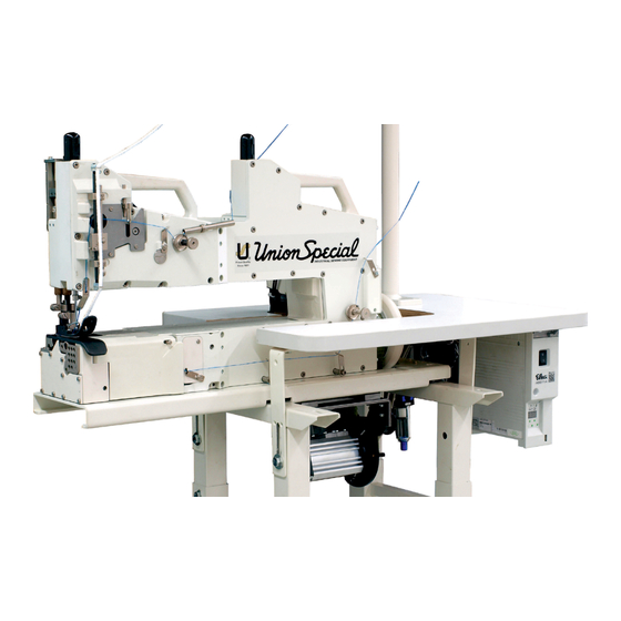
HIGH-SPEED BAG MAKING MACHINES BML211C2
HOCHLEISTUNGS-SACKNÄHMASCHINEN BML211C2
MANUAL NO. / KATALOG NR.
FOR STYLES / FÜR TYPEN
07/2023
ORIGINAL INSTRUCTIONS
ORIGINALBETRIEBSANLEITUNG
: CAT-BML211C2-EN-DE
: BML211C2
BML211C2
Advertisement
Table of Contents

Related Manuals for UnionSpecial BML211C2


Summary of Contents for UnionSpecial BML211C2
- Page 1 ORIGINAL INSTRUCTIONS ENGINEER´S AND ILLUSTRATED PARTS MANUAL ORIGINALBETRIEBSANLEITUNG WARTUNGSANLEITUNG UND ILLUSTRIERTES TEILEVERZEICHNIS BML211C2 HIGH-SPEED BAG MAKING MACHINES BML211C2 HOCHLEISTUNGS-SACKNÄHMASCHINEN BML211C2 MANUAL NO. / KATALOG NR. : CAT-BML211C2-EN-DE FOR STYLES / FÜR TYPEN : BML211C2 07/2023...
-
Page 3: Preface
MANUAL NO. CAT-BML211C2 KATALOG NR. CAT-BML211C2 INSTRUCTIONS FOR BETRIEBSANLEITUNG FÜR BML211C2 Bag-Making Machines BML211C2 Sacknähmaschinen First Edition ©2023 Erste Auflage ©2023 Union Special GmbH Rights reserved in all Countries Weltweit beanspruchte Union Special GmbH Rechte PREFACE VORWORT This manual assists you in the operation and main-... -
Page 4: Safety Rules
SAFETY RULES SICHERHEITSHINWEISE Before putting the machine described in Lesen Sie vor Inbetriebnahme der in diesem this manual into service, carefully read the Katalog beschriebenen Maschine die Betriebs- instructions. Starting up your machine is only anleitung sorgfältig durch. Jede Maschine darf permitted after taking note of the instructions erst nach Kenntnisnahme der Betriebs- and by qualified operators. - Page 5 8.2. While replacing any parts such as needle(s), 8.2. Zum Auswechseln von Nähwerkzeugen wie Nadel, Drückerfuß, Stichplatte, Greifer, Leger, presser foot, throat plate, looper, spreader, feed dog, needle guard, folder, fabric guide Transporteur, Nadelanschlag, Apparat, etc. Nähgutführung usw. 8.3. When leaving the workplace and during unat- 8.3.
-
Page 7: Table Of Contents
TABLE OF CONTENTS INHALTSVERZEICHNIS Preface ..............3 Vorwort ..............3 Safety Rules ............4 Sicherheitshinweise ..........4 Machine Description ..........9 Maschinenbeschreibung.......... 9 Operating Instructions ........... 10 Bedienungsanleitung ..........10 Cleaning ..............10 Reinigung .............. 10 Caution Areas ............11 Gefährdungszonen .......... -
Page 9: Machine Description
Stops adjustable in needle up or down position and Stopps einstellbar in Nadelhoch- und Nadeltiefstel- simultaneously lifting the presser foot. lung bei gleichzeitigem Anheben des Drückerfußes. BML211C2 is a single-needle two-thread double BML211C2 ist eine Einnadel-Zweifaden-Doppel- locked stitch longarm bag-making machine with rust kettenstich-Langarm-Sacknähmaschine mit rost- protected extermal parts. -
Page 10: Operating Instructions
OPERATING INSTRUCTIONS BEDIENUNGSANLEITUNG Starting up the machine Inbetriebnahme Prior to leaving our factory each machine is carefully Vor Verlassen unseres Werks wurde jede Maschine inspected, adjusted and given a function test. How- sorgfältig geprüft, eingestellt und ein Funktionstest ever, upon receipt the machine should be inspected durchgeführt. -
Page 11: Caution Areas
CAUTION AREAS GEFÄHRDUNGSZONEN... -
Page 12: Inserting Needle
INSERTING NEEDLE EINSETZEN DER NADEL The standard needle is 9848GF300/120. Insert Die Standardnadel ist 9848GF300/120. Setzen Sie needle according to the following procedure: die Nadel wie folgt ein: 1. Bring the needle head (A) to the highest posi- 1. Bringen Sie den Nadelkopf (A) in die obere tion. -
Page 13: Threading The Machine
THREADING THE MACHINE EINFÄDELN DER MASCHINE Turn off main power supply before Schalten Sie vor dem Einfädeln den threading! When using clutch motors Hauptschalter aus! Beim Gebrauch without actuation lock wait until von Kupplungsmotoren ohne Betä- motor has completely stopped. tigungssperre ist der Stillstand des Motors abzuwarten. -
Page 14: Threading The Machine Fillercord
THREADING THE MACHINE EINFÄDELN DER MASCHINE FILLERCORD DICHTKORDEL... -
Page 15: Oil Specification Requirements
OIL SPECIFICATION REQUIREMENTS ERFORDERLICHE ÖL-SPEZIFIKATIONEN All oils shall be non compounded, straight mineral Sämtliche Öle sollten ungebundene, pure Mineral- oils, of high viscosity index (will not thin down exces- öle mit hoher Viskosität sein (verdünnen sich bei sively with heat). Practically all oil companies have Hitze nicht übermäßig). -
Page 16: Lubrication
LUBRICATION ÖLEN CAUTION! Oil has been drained from the machine ACHTUNG: Vor dem Versand wurde das Öl aus before shipping and the reservoir must be filled der Maschine abgelassen, der Ölbehälter muß des- before starting operation. Use the oil with UNION halb vor der Inbetriebnahme gefüllt werden. - Page 17 flow or an obstruction in the oil line or oil siphon zu gehen, dass sie nicht abgeknickt sind filters. und den Ölfluss behindern oder ob die Öllei- tung oder der Öl-Syphon-Filter verstopft sind. 1. RECOMMENDATION: Change oil and filters after the first 500 hours of operation. There- 1.
-
Page 18: Oil Flow Diagram
OIL FLOW DIAGRAM ÖLFLUSS-DIAGRAMM The oiling system distributes pressurized oil Die Druckschmierung leitet das Öl mit 0,3 - 1 bar 4-15 PSI (0.3 - 1 bar) through an oil distributor (A) to über einen Druckverteiler (A) an vier Lagerstellen four bearings (B), (E), (C), (D). From there the oil is (B), (E), (C), (D). -
Page 20: Maintenance Plan
MAINTENANCE PLAN WARTUNGSPLAN On a daily basis at the beginning of shift work Täglich bei Schichtbeginn 1. Check oil level at oil gauge glass after 1. Ölspiegel im Ölschauglas nach closing 30 to 40 bags. 30 bis 40 Säcken kontrollieren. 2. -
Page 21: Adjusting The Stitch Length
ADJUSTING THE STITCH LENGTH STICHLÄNGEN-EINSTELLUNG 1. Remove plug (A). 1. Entfernen Sie die Schraube (A). 2. Turn handwheel until center adjustment screw 2. Drehen Sie die Riemenscheibe bis die Einstell- (B) is visible. schraube (B) mittig sichtbar wird. 3. Turn adjustment screw (B) clockwise to lengthen 3. -
Page 22: Feed Dog Setting
FEED DOG SETTING TRANSPORTEUR-EINSTELLUNG Set the height of the feed dog into its highest posi- Stellen Sie die Höhe des Transporteurs in seiner tion so that the rear teeth protrude .060” (1.5mm) höchsten Stellung so ein, dass die hinteren Zähne above the throat plate surface. -
Page 23: Looper Setting
LOOPER SETTING GREIFER-EINSTELLUNG Set the looper point to .196” (5mm) from the center- In der rechten Endposition des Greifers stellen Sie line of the needle when the looper is at its furthest die Greiferspitze 5 mm zur Nadelmitte ein. Die position to the right. -
Page 24: Needle Guard Setting
NEEDLE GUARD SETTING NADELANSCHLAG-EINSTELLUNG 1. Slip shaft of guard onto holder. 1. Schieben Sie den Schaft des Anschlags in den Halter. 2. Position the guard approximately to the middle 2. Setzen Sie den Anschlag etwa mittig in die Aus- of the rubber sealing frame. sparung des Gummi-Dichtrahmens. -
Page 25: Looper Thread Control
LOOPER THREAD CONTROL GREIFERFADENKONTROLLE 1. Set the looper thread take-up to just contact the 1. Stellen Sie den Greiferfadenabzugshebel so ein, thread when the needle enters the throat plate dass er gerade den Faden berührt, wenn die on its downward travel. Nadelspitze sich in ihrer Abwärtsbewegung an der Oberkante der Stichplatte befindet. -
Page 26: Stitch Formation And Thread Tension
STITCH FORMATION AND STICHBILDUNG UND FADEN- THREAD TENSION SPANNUNG Set the needle thread tension to be light enough to Stellen Sie die Nadelfadenspannung so ein, dass maintain a needle loop at the tip of the needle on bei Bildung einer halben Stichlänge eine ausrei- half the length of one stitch. -
Page 28: Needle-Looper Synchronisation
NEEDLE-LOOPER SYNCHRONISATION NADEL-GREIFER-SYNCHRONISATION... - Page 29 Synchronize with TT148 Synchroni- Synchonisieren mit Synchronisier- sation Gauge Kit Teilesatz TT148 Remove the looper and insert the test pin (I), Entfernen Sie den Greifer und setzen Sie den (1/4“ (6.3mm) diameter x 1 3/4“ (4.5mm) long) Teststift (I) (6,3mm Durchmesser x 44,5 mm lang) into the looper holder and lock the rod when in den Greiferhalter und ziehen Sie ihn fest, there is 1/4“...
-
Page 30: Needle-Looper Synchronisation
NEEDLE-LOOPER SYNCHRONISATION NADEL-GREIFER-SYNCHRONISATION... - Page 31 Synchronize without TT148 Syn- Synchronisieren ohne Synchroni- sier-Teilesatz TT148 chronisation Gauge Kit Falls keine Messuhr verfügbar ist, führen If no indicator is available, set the synchro- Sie die Synchronisierungsmessung mit einer nisation measurement with a slide caliper or Schieblehre oder einem Stahllineal durch. steel ruler.
-
Page 32: Needles
NEEDLES NADELN Each needle has both a type and a size number. Jede Nadel hat eine Typ- und eine Dickennummer. The type number denotes the kind of shank, point, Die Typnummer bezeichnet die Art des Nadel- length, groove, finish and other details. The size kolbens, der Spitze, Länge, Rinne, Oberfläche und number, stamped on the needle shank, denotes andere Einzelheiten. -
Page 33: Troubleshooting
TROUBLESHOOTING FEHLERSUCHE PROBLEMS CAUSE AND SOLUTION PROBLEME URSACHE UND LÖSUNG Needle thread wraps CAUSE: Chaining section not clamping Nadelfaden wickelt URSACHE: Fadenkette wir nicht vom sich um den Greifer. Kettelteil geklemmt. around looper. chain. SOLUTION: Set chaining section to LÖSUNG: Positionieren Sie das specification. -
Page 34: Ordering Wear And Spare Parts
ORDERING WEAR AND SPARE BESTELLUNG VON VER- PARTS SCHLEISS- UND ERSATZTEILEN The following section of this manual simplifies Der folgende Teil dieses Katalogs vereinfacht die ordering spare parts. Exploded views of various Bestellung von Verschleiß- und Ersatzteilen. sections of the mechanism show the actual Explosionszeichnungen der einzelnen Gruppen des position of the spares in the machine. -
Page 35: Views And Description Of Parts
VIEWS AND DESCRIPTION OF PARTS DARSTELLUNGEN UND TEILEBESCHREIBUNGEN... - Page 36 BUSHINGS BUCHSEN...
- Page 37 BUSHINGS BUCHSEN Part No. Ref. No. Qty. Req. Description Beschreibung Teil Nr. Pos. Nr. Anzahl 10044AL Bushing, needle bar, upper Nadelstangenbuchse ** *2. 10054D Bushing, needle bar, lower Nadelstangenbuchse 10044BR Bushing, presser bar Buchse 660-1033 Lip Seal Wellendichtring 10044CGL Bushing, needle bar con- Buchse, Nadelfadenkontrolle trol 10044DGL...
- Page 38 NEEDLE BAR DRIVE NADELSTANGENANTRIEB...
- Page 39 NEEDLE BAR DRIVE NADELSTANGENANTRIEB Part No. Ref. No. Qty. Req. Description Beschreibung Teil Nr. Pos. Nr. Anzahl 10096G Guard, needle bar Nadelstangenschutz 660-1141 „O“ Ring Dichtring 10017B Needle bar Nadelstange C10018C Needle head Nadelkopf CSS6110650TP Screw Schraube 9848GF300/120 Needle Nadel 10016B Needle bar connection Nadelstangenverbindung...
- Page 40 UPPER MAIN SHAFT OBERE HAUPTWELLE...
- Page 41 UPPER MAIN SHAFT OBERE HAUPTWELLE Part No. Ref. No. Qty. Req. Description Beschreibung Teil Nr. Pos. Nr. Anzahl 10022F Main shaft, upper Obere Hauptwelle TA0370601M0 Plug Stopfen 10040B Eccentric Exzenter SS8660612TP Set screw Gewindestift 660-1029 Retaining ring Sicherungsring 29476ZS Bearing assembly Kugellager SS8660612TP Set screw...
- Page 42 CRANKSHAFT ASSEMBLY KURBELWELLE, KOMPLETT...
- Page 43 CRANKSHAFT ASSEMBLY KURBELWELLE, KOMPLETT Ref. No. Part No. Qty. Req. Description Beschreibung Pos. Nr. Teil Nr. Anzahl 29126FT Crankshaft Assembly Kurbelwelle komplett 660-1028 „O“ Ring Dichtungsring SS6151440SP Screw Schraube 660-1104 „O“ Ring Dichtungsring SS4111215SP Screw Schraube 10042C Flange Cover Flanschabdeckung 660-1031 Bearing Lager...
- Page 44 LOOPER DRIVE AND NEEDLE GUARD DRIVE GREIFER- UND NADELANSCHLAGANTRIEB...
- Page 45 LOOPER DRIVE AND NEEDLE GUARD DRIVE GREIFER- UND NADELANSCHLAGANTRIEB Part No. Ref. No. Qty. Req. Description Beschreibung Teil Nr. Pos. Nr. Anzahl G20025 Needle Guard Nadelanschlag C10022E Shaft, needle guard Welle für Nadelanschlag CSS8150510TP Set screw Gewindestift 10035 Fork, needle guard Gabel für Nadelanschlag SS8660612TP Set screw...
- Page 46 KNIFE DRIVE AND THROAT PLATE SUPPORT (OPTIONAL) MESSERANTRIEB UND STICHPLATTENTRÄGER (OPTIONAL) Torque: 26 in lb Drehmoment: 3Nm Torque: 30 in ob Drehmoment: 3.5Nm Torque: 17 in lb Drehmoment: 2Nm Torque: 26 in lb Drehmoment: 3 Nm...
- Page 47 KNIFE DRIVE AND THROAT PLATE SUPPORT (OPTIONAL) MESSERANTRIEB UND STICHPLATTENTRÄGER (OPTIONAL) Part No. Ref. No. Qty. Req. Description Beschreibung Teil Nr. Pos. Nr. Anzahl CSS4150915SP Screw Schraube C10080W Support, throat plate Stichplattenträger C10050B Knife holder, movable Messerhalter, beweglich CSS8150822TP Screw Schraube 10047F Stift...
- Page 48 FEED MECHANISM TRANSPORTMECHANISMUS...
- Page 49 FEED MECHANISM TRANSPORTMECHANISMUS Part No. Ref. No. Qty. Req. Description Beschreibung Teil Nr. Pos. Nr. Anzahl CSS6121050SP Screw Schraube C10034G Sealing frame Dichtrahmen C10034E Sealing washer Dichtplatte G10084B Bellow assembly Dichtbalg, komplett CSS6110710TP Screw Schraube 10033G Block clamp Pratze SS9112520SP Screw Schraube WP0460556SD...
- Page 50 OIL PUMP ÖLPUMPE...
- Page 51 OIL PUMP ÖLPUMPE Part No. Ref. No. Qty. Req. Description Beschreibung Teil Nr. Pos. Nr. Anzahl A10535 Oil Tube, Suction Ölansaugrohr 660-3003 Rotary Fitting Schwenkverschraubung 10093T Clamp, Oil Tube Halter für Ölrohr WP0531000SE Washer Scheibe SS6121210SP Screw Schraube SM6051202TP Screw Schraube 10093CS Oil Deflection Plate...
- Page 52 OIL TUBES ÖLSCHLÄUCHE...
- Page 53 OIL TUBES ÖLSCHLÄUCHE Part No. Ref. No. Qty. Req. Description Beschreibung Teil Nr. Pos. Nr. Anzahl 10093AH Oil Tube, 220mm long Ölschlauch, 220 mm lang 10093-4 Oil Tube, 178mm long Ölschlauch, 178 mm lang 10093-2 Oil Tube, 280mm long Ölschlauch, 280 mm lang 10093AH Oil Tube, 220mm long Ölschlauch, 220 mm lang...
- Page 54 OIL DISTRIBUTOR ASSEMBLY ÖLVERTEILER, KOMPLETT...
- Page 55 OIL DISTRIBUTOR ASSEMBLY ÖLVERTEILER, KOMPLETT Part No. Ref. No. Qty. Req. Description Beschreibung Teil Nr. Pos. Nr. Anzahl 10084 Gasket Dichtung GR10093A Oil Distributor Ölverteiler Oil Tube Ölrohr WP0531000SE Washer Scheibe SM6052002TP Screw Schraube 671D57 Oil Level Gauge Ölschauglas 10093AU Oil Pressure Gauge Öldruckanzeiger 999-196...
- Page 56 NEEDLE THREAD CONTROL NADELFADENKONTROLLE...
- Page 57 NEEDLE THREAD CONTROL NADELFADENKONTROLLE Part No. Ref. No. Qty. Req. Description Beschreibung Teil Nr. Pos. Nr. Anzahl C10047D Stift C10066 Holder, Thread Guide Halter für Fadenführung CSS8120740SP Set Screw Gewindestift C10066A Thread Guide Fadenführung C10082Q Cover Abdeckung CSS6121050SP Screw Schraube C10066C Support, Thread Control Halter für Fadenkontrolle...
- Page 58 LOOPER THREAD CONTROL GREIFERFADENKONTROLLE...
- Page 59 LOOPER THREAD CONTROL GREIFERFADENKONTROLLE Part No. Ref. No. Qty. Req. Description Beschreibung Teil Nr. Pos. Nr. Anzahl C10068C Thread Guide Fadenführung CSS1120710SP Screw Schraube C10068D Thread Guide Fadenführung 10068E Eyelet Öse C10023B Thread Take-up Greiferfadenaufnehmer CSS9151630CP Screw Schraube CSS6121050SP Screw Schraube 10082A Cover...
- Page 60 FRONT AND LOOPER COVERS VORDERE ABDECKUNG UND GREIFERABDECKUNG...
- Page 61 FRONT AND LOOPER COVERS VORDERE ABDECKUNG UND GREIFERABDECKUNG Part No. Ref. No. Qty. Req. Description Beschreibung Teil Nr. Pos. Nr. Anzahl 10082AW Front Cover Frontdeckel 660-1094 Stift 96535 Stift 660-1067 Stift TA2351004RO Plug Verschlussstopfen 660-1127 Lip Seal Wellendichtring C10033D Collar Stellring CSS8120740SP Screw...
- Page 62 COVERS ABDECKUNGEN...
- Page 63 COVERS ABDECKUNGEN Part No. Ref. No. Qty. Req. Description Beschreibung Teil Nr. Pos. Nr. Anzahl CSS6120940SP Screw Schraube 10082AU Cover lateral Abdeckung seitlich 10084L Seal Dichtung 10082F Cover front Abdeckung vorne C22599G Screw Schraube C524 Spring Feder C10095A Bolt Bolzen...
- Page 64 BACK AND RIGHT COVERS HINTERE UND RECHTE ABDECKUNG...
- Page 65 BACK AND RIGHT COVERS HINTERE UND RECHTE ABDECKUNG Part No. Ref. No. Qty. Req. Description Beschreibung Teil Nr. Pos. Nr. Anzahl C22894BM Screw Schraube TA1050504R0 Plug, cap Verschlussstopfen 10082J Cover Abdeckung Dust Ring Staubring GR-10094 Vent Entlüftungsschraube 10093AM **6. Oil Tube 6x4; 0.33m long Ölrohr 6x4;...
- Page 66 PRESSER FOOT LIFT DRÜCKERFUSSLIFTUNG...
- Page 67 PRESSER FOOT LIFT DRÜCKERFUSSLIFTUNG Part No. Ref. No. Qty. Req. Description Beschreibung Teil Nr. Pos. Nr. Anzahl 29803 Presser foot lifter kit Kit pneumatische Liftung 29801C Cylinder bracket Zylinderhalter 96101 Serrated lock washer Fächerscheibe A5,3 95255 Mutter M5 95409D Screw Schraube M4x12 95954 Washer...
- Page 68 SEWING COMBINATION NÄHTEILE...
- Page 69 SEWING COMBINATION NÄHTEILE Part No. Ref. No. Qty. Req. Description Beschreibung Teil Nr. Pos. Nr. Anzahl C20020P Presser Foot Drückerfuß C10030T Presser Foot Shank Drückerfuß CSS8120740SP Screw Schraube CSS9151420TP Set Screw Gewindestift C10047C Dowl Pin Paßstift C20030AD Presser Foot Bottom Drückerfußsohle C22599L Screw...
- Page 70 DRIVE ELEMENTS ANTRIEBSELEMENTE...
- Page 71 DRIVE ELEMENTS ANTRIEBSELEMENTE Part No. Ref. No. Qty. Req. Description Beschreibung Teil Nr. Pos. Nr. Anzahl G9469Q Pulley complete Handrad komplett 96501A Cylindrical pin Zylinderstift A9469QBZ Pulley hub Nabe für Handrad 999-235AT10B Driven sprocket Zahnriemenrad getrieben Screw Schraube 10021G Pulley Handrad G22574 Screw...
- Page 72 THREAD STAND AND BASE PLATE FADENSTÄNDER UND GRUNDPLATTE...
- Page 73 THREAD STAND AND BASE PLATE FADENSTÄNDER UND GRUNDPLATTE Part No. Ref. No. Qty. Req. Description Beschreibung Teil Nr. Pos. Nr. Anzahl 93065D3WS Thread Stand, 3 Cones Fadenständer, 3teilig 93065DA Thread Stand Base Fadenständerfuß 93065DC2 Cone Support Fadenträger 93065DC3 Cone Support Fadenträger 95067 Screw...
- Page 74 ACCESSORIES ZUBEHÖR...
- Page 75 ACCESSORIES ZUBEHÖR Ref. No. Part No. Qty. Req. Description Beschreibung Pos. Nr. Teil Nr. Anzahl 22933105 Screwdriver Schraubendreher 22933006 Screwdriver Schraubendreher 118G Tweezers Pinzette WR83 Allen Wrench 5mm T-Griff 5 mm 9848GF300/120 Needle Nadel 28604U Oil Bottle 0.5 l Ölbehälter 0,5 l *6A.
-
Page 76: Numerical Index Of Parts
NUMERICAL INDEX OF PARTS NUMERISCHES TEILEVERZEICHNIS Part No. Part No. Page Page Teile Nr. Teile Nr. Seite Seite 6-899-4MM-6MM ..........53 660-1127 ............61 660-1137 ............37 118G ..............75 660-1138 ............37 660-1141 ............39 660-212 .............. 41 660-1147 ............41 660-705 .............. - Page 77 Page Page Part No. Part No. Seite Seite Teile Nr. Teile Nr. 10017B .............. 39 10042K .............. 41 10043 ..............45 10021D .............. 41 10021E .............. 41 10044AH ............37 10021G .............. 71 10044AL ............37 10022 ..............43 10044AU ............37 10022B ..............
- Page 78 Part No. Page Part No. Page Teile Nr. Seite Teile Nr. Seite 10093T ............... 51 10068E .............. 59 10070E .............. 47 10093U .............. 51 10073 ..............47 10095B .............. 49 10073A ............... 47 10095BN ............67 10076 ..............41 10095BP ............67 10095C ..............
- Page 79 Part No. Page Part No. Page Teile Nr. Seite Teile Nr. Seite 93065D3WS ............73 93065DA ............73 B3517009000 ............ 49 93065DB ............73 93065DC2 ............73 C28C ..............57 93065DC3 ............73 C88 ..............67 93065DD ............73 93065DE ............73 C107D ............
- Page 80 Part No. Page Part No. Page Teile Nr. Seite Teile Nr. Seite C10066A ............57 CSS1120710SP ......... 47, 57, 59 C10066B ............57 CSS4150915SP ..........47 C10066C ............57 CSS4151215SP ..........41 C10066D ............57 CSS6110650TP ..........39 CSS6110710TP ..........49 C10068B ............
- Page 81 Part No. Page Part No. Page Teile Nr. Seite Teile Nr. Seite GR10093A ............55 SS9110543CP ........... 47 GR-10094 ............65 SS9112520SP ........... 49 GR-95055 ............65 SS9151120CP ........... 41 GR95953 ............41 SS9151740CP ........... 49 HS110A .............. 67 TA0370601M0 ........... 41 TA1050504R0 ............
- Page 82 Corporate Office : Union Special LLC One Union Special Plaza Huntley, IL 60142, USA Phone: +1 847 669 4500 Fax: +1 847 669 4239 e-mail: bag@unionspecial.com www.unionspecial.com European Distribution Center : Union Special GmbH Raiffeisenstrasse 3 D-71696 Möglingen, Germany Tel:...
Need help?
Do you have a question about the BML211C2 and is the answer not in the manual?
Questions and answers