Table of Contents
Advertisement
Quick Links
CopperLink Model 1214E
Extended Temperature
Ethernet Extender
User Manual
Important
This is a Class A device and is not intended for use in a residential environment.
Sales Office:
+1 (301) 975-1000
Technical Support:
+1 (301) 975-1007
E-mail:
support@patton.com
WWW:
www.patton.com
Part Number: 07MCL1214E-UM, Rev. C
Revised: October 9, 2014
Advertisement
Table of Contents

Related Manuals for Patton CopperLink 1214E


Summary of Contents for Patton CopperLink 1214E
-
Page 1: User Manual
Important This is a Class A device and is not intended for use in a residential environment. Sales Office: +1 (301) 975-1000 Technical Support: +1 (301) 975-1007 E-mail: support@patton.com WWW: www.patton.com Part Number: 07MCL1214E-UM, Rev. C Revised: October 9, 2014... - Page 2 Under no condition shall Patton Electronics be liable for any damages incurred by the use of this product. These damages include, but are not limited to, the following: lost profits, lost savings and incidental or consequential damages arising from the use of or inability to use this product.
-
Page 3: Summary Table Of Contents
Summary Table of Contents General Information ............................13 Installing the CL1214E............................16 Configuration and Operation..........................20 Contacting Patton for assistance......................... 24 Compliance Information ........................... 27 Specifications ..............................29 Factory Replacement Parts and Accessories ......................31 Interface Pin Assignment ..........................33 Line Rate and Reach ............................ -
Page 4: Table Of Contents
............................11 General Conventions General Information ............................13 CopperLink 1214E Overview..........................14 ..............................14 Key Features ..........................15 CopperLink 1214E Front Panel Installing the CL1214E............................16 Planning the Installation............................17 ..........................18 Connecting the Line Interface ..............18 Connecting the Line Interface for CL1214E/EUI or CL1214E/TB Connecting the 10/100Base-T Ethernet Interface....................19... - Page 5 ..............................30 External AC ..............................30 External DC .................................30 Physical Factory Replacement Parts and Accessories ......................31 ................32 CopperLink 1214E Factory Replacement Parts and Accessories Interface Pin Assignment ..........................33 ............................34 10/100Base-T Interface ............................34 CopperLink Interface Line Rate and Reach ............................35 Line Rate and Reach Chart, Based on 24 AWG (0.5...
-
Page 6: List Of Figures
List of Figures Typical application ..............14 CL1214E front panel . -
Page 7: List Of Tables
List of Tables General conventions ..............11 CL1214E LED description . -
Page 8: About This Guide
33 provides an overview of terms within this manual • Appendix E on page 35 provides a line range and reach chart for the CL1214E For best results, read the contents of this guide before you install the CopperLink 1214E. - Page 9 CopperLink 1214E User Manual About This Guide Precautions Notes and cautions, which have the following meanings, are used throughout this guide to help you become aware of potential Router modem problems. Warnings relate to personal injury issues, and Cautions refer to potential property damage.
-
Page 10: Safety When Working With Electricity
CopperLink 1214E User Manual About This Guide Safety When Working With Electricity • Do not open the device when the power cord is connected. For systems without a power switch and without an external power adapter, line volt- ages are present within the device when the power cord is connected. -
Page 11: General Observations
CopperLink 1214E User Manual About This Guide Electrostatic Discharge (ESD) can damage equipment and impair electrical circuitry. It occurs when electronic printed circuit cards are improperly handled and can result in complete or inter- CAUTION mittent failures. Do the following to prevent ESD: Always follow ESD prevention procedures when removing and replacing cards. - Page 12 CopperLink 1214E User Manual About This Guide Table 1. General conventions Convention Meaning node The leading IP address or nodename of a SmartNode is substituted with node in boldface italic font. The leading SN on a command line represents the nodename of the SmartNode...
-
Page 13: General Information
Chapter 1 General Information Chapter contents CopperLink 1214E Overview..........................14 Key Features ..............................14 CopperLink 1214E Front Panel ..........................15... -
Page 14: Copperlink 1214E Overview
1 • General Information CopperLink 1214E Overview The Patton CopperLink 1214E modems provide high-speed LAN connections between peered Ethernet LANs, remote PCs, or any other network-enabled 10/100Base-T device. Operating in pairs, one CL1214E is configured as the (L) Local unit located at one end of the LAN extension and the other CL1214E is configured as the (R) Remote unit at the other end. -
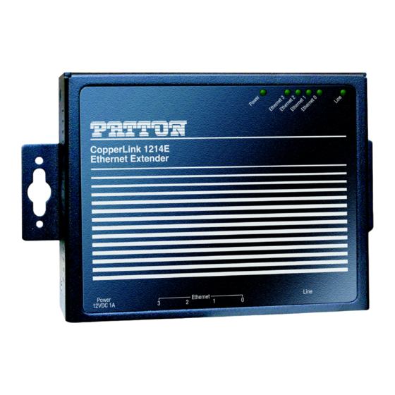
Page 15: Copperlink 1214E Front Panel
CopperLink 1214E User Manual 1 • General Information CopperLink 1214E Front Panel The CL1214E features six front panel LEDs that monitor power, the Ethernet signals, the CopperLink con- nection, and the remote/local setting. Figure 2 shows the front panel location of each LED. -
Page 16: Installing The Cl1214E
Chapter 2 Installing the CL1214E Chapter contents Planning the Installation............................17 Connecting the Line Interface ..........................18 Connecting the Line Interface for CL1214E/EUI or CL1214E/TB ..............18 Connecting the 10/100Base-T Ethernet Interface....................19 Connecting Power ..............................19... -
Page 17: Planning The Installation
CopperLink 1214E User Manual 2 • Installing the CL1214E Planning the Installation The Interconnecting cables shall be accept- able for external use and shall be rated for the proper application with respect to voltage, CAUTION current, anticipated temperature, flammability, and mechanical serviceability. -
Page 18: Connecting The Line Interface
2 • Installing the CL1214E Connecting the Line Interface The CopperLink 1214E supports communication between two peer Ethernet LAN sites over a distance of up to 10,000 ft (3 km) over 24 AWG (0.5 mm) twisted-pair wire or Cat5+. Note Actual distance and link performance may vary depending on the environ- ment and type/gauge of wire used. -
Page 19: Connecting The 10/100Base-T Ethernet Interface
CopperLink 1214E User Manual 2 • Installing the CL1214E Connecting the 10/100Base-T Ethernet Interface The Interconnecting cables shall be accept- able for external use and shall be rated for the proper application with respect to voltage, CAUTION current, anticipated temperature, flammability, and mechanical serviceability. -
Page 20: Configuration And Operation
Chapter 3 Configuration and Operation Chapter contents Introduction ................................21 Configuring the Hardware DIP Switches ......................21 Configuring DIP Switch S1 ..........................22 Switch S1-1: Local/Remote Configuration ....................22 Switches S1-2 and S1-3: Symmetric/Asymmetric Operation ..............22 Switch S1-5: General Protection (Signal to Noise Ratio) ................23... -
Page 21: Introduction
CopperLink 1214E User Manual 3 • Configuration and Operation Introduction The CL1214E has eight DIP switches (S1) for configuring the unit for a wide variety of applications. This sec- tion describes switch locations and explains the different configurations. Once the CL1214E’s are properly installed, they should operate transparently. No user settings required. -
Page 22: Configuring Dip Switch S1
CopperLink 1214E User Manual 3 • Configuration and Operation Configuring DIP Switch S1 DIP Switch S1 is where you configure the CopperLink line. The following tables describe the configuration for the 1214E. Table 3. S1 Summary Position Description S1-1 Local/Remote Configuration... -
Page 23: Signal To Noise Ratio
CopperLink 1214E User Manual 3 • Configuration and Operation Switch S1-5: General Protection (Signal to Noise Ratio) Use Switch S1-5 to configure line noise protection. Table 6. Signal to Noise Ratio S1-5 Setting • 6dB: Original line noise protection with 6dB SNR •... -
Page 24: Contacting Patton For Assistance
Chapter 4 Contacting Patton for assistance Chapter contents Introduction ................................25 Contact information..............................25 Warranty Service and Returned Merchandise Authorizations (RMAs)..............25 Warranty coverage ............................25 Out-of-warranty service ..........................25 Returns for credit ............................25 Return for credit policy ..........................26 RMA numbers ..............................26 Shipping instructions ..........................26... -
Page 25: Introduction
If you have ordered the wrong equipment or you are dissatisfied in any way, please contact us to request an RMA number to accept your return. Patton is not responsible for equipment returned without a Return Authorization. -
Page 26: Rma Numbers
RMA#: xxxx 7622 Rickenbacker Dr. Gaithersburg, MD 20879-4773 USA Patton will ship the equipment back to you in the same manner you ship it to us. Patton will pay the return shipping costs. Warranty Service and Returned Merchandise Authorizations (RMAs) -
Page 27: Compliance Information
Appendix A Compliance Information Chapter contents Compliance ................................28 ................................28 Low-Voltage Directive (Safety) ........................28 PSTN ................................28 Radio and TV Interference ............................28 CE Declaration of Conformity ..........................28 Authorized European Representative ........................28... -
Page 28: Compliance
CE Declaration of Conformity Patton Electronics, Inc declares that this device is in compliance with the essential requirements and other rele- vant provisions of Directive 2004/108/EC relating to electromagnetic compatibility, Directive 2006/95/EC relating to electrical equipment designed for use within certain voltage limits and Directive 2011/65/EU relat- ing to RoHS compliance. -
Page 29: Specifications
Appendix B Specifications Chapter contents Connection..............................30 CopperLink Connection ..........................30 CopperLink Line Rate and CopperLink Distance....................30 Line Rate ................................30 Distance ................................30 LED Status Indicators ............................30 Power Supply ................................30 External AC ..............................30 External DC ..............................30 Physical .................................30... -
Page 30: Lan Connection
CopperLink 1214E User Manual B • Specifications LAN Connection Four RJ-45, 10/100Base-T, IEEE 802.3 Ethernet CopperLink Connection RJ-45 CopperLink Line Rate and CopperLink Distance Line Rate Up to 200 Mbps asymmetrical Distance Up to 9,842 ft (3 km) Note Distances depend on line rate and line conditions LED Status Indicators Power, Local and Remote—Green... -
Page 31: Factory Replacement Parts And Accessories
Appendix C Factory Replacement Parts and Accessories Chapter contents CopperLink 1214E Factory Replacement Parts and Accessories ................32... -
Page 32: Copperlink 1214E Factory Replacement Parts And Accessories
CopperLink 1214E User Manual C • Factory Replacement Parts and Accessories CopperLink 1214E Factory Replacement Parts and Accessories Table 7. CL1214E Factory Replacement Parts and Accessories Patton Model # Description CL1214E/CC/12 Extended Temperature CopperLink High Speed Auto Rate Extender Conformal Coated; RJ45; -12VDC Input... -
Page 33: Interface Pin Assignment
Appendix D Interface Pin Assignment Chapter contents 10/100Base-T Interface ............................34 CopperLink Interface ............................34... -
Page 34: 10/100Base-T Interface
CopperLink 1214E User Manual D • Interface Pin Assignment 10/100Base-T Interface RJ-45 • Pin 1: TX+ • Pin 2: TX- • Pin 3: RX+ • Pin 6: RX- • Pins 4, 5, 7, 8: No connection CopperLink Interface RJ-45 •... -
Page 35: Line Rate And Reach
Appendix E Line Rate and Reach Chapter contents Line Rate and Reach Chart, Based on 24 AWG (0.5 MM)..................36... -
Page 36: Line Rate And Reach Chart, Based On 24 Awg (0.5 Mm)
CopperLink 1214E User Manual E • Line Rate and Reach Line Rate and Reach Chart, Based on 24 AWG (0.5 mm) Table 8. Line Rate & Reach Chart Using Twisted-Pair (Long Range) Distance in Feet Mbps Mode (Long Range) m/km...
Need help?
Do you have a question about the CopperLink 1214E and is the answer not in the manual?
Questions and answers