Table of Contents
Advertisement
Quick Links
Copyright
Copyright © 2016 MiTAC International Corporation. All rights reserved. No part of
this manual may be reproduced or translated without prior written consent from
MiTAC International Corporation.
Trademark
All registered and unregistered trademarks and company names contained in this
manual are property of their respective owners including, but not limited to the
following.
®
TYAN
is a trademark of MiTAC International Corporation.
®
Intel
is a trademark of Intel
AMI, AMI BIOS are trademarks of AMI Technologies.
®
®
Microsoft
, Windows
®
Winbond
is a trademark of Winbond Electronics Corporation.
Notice
Information contained in this document is furnished by MiTAC International
Corporation and has been reviewed for accuracy and reliability prior to printing.
MiTAC assumes no liability whatsoever, and disclaims any express or implied
warranty, relating to sale and/or use of TYAN
warranties relating to fitness for a particular purpose or merchantability. MiTAC
retains the right to make changes to product descriptions and/or specifications at
any time, without notice. In no event will MiTAC be held liable for any direct or
indirect, incidental or consequential damage, loss of use, loss of data or other
malady resulting from errors or inaccuracies of information contained in this
document.
All manuals and user guides at all-guides.com
S5539
Version 1.0
®
Corporation.
are trademarks of Microsoft Corporation.
1
http://www.tyan.com
®
products including liability or
Advertisement
Table of Contents

Subscribe to Our Youtube Channel
Related Manuals for MiTAC TYAN S5539


Summary of Contents for MiTAC TYAN S5539
-
Page 1: S5539
In no event will MiTAC be held liable for any direct or indirect, incidental or consequential damage, loss of use, loss of data or other malady resulting from errors or inaccuracies of information contained in this document. -
Page 2: Table Of Contents
All manuals and user guides at all-guides.com Contents S5539 ......................1 Before you begin… ..................3 Chapter 1: Instruction ................4 1.1 Congratulations ................. 4 1.2 Hardware Specifications ..............4 1.3 Software Specifications ..............7 Chapter 2: Board Installation ..............8 2.1 Board Image .................. -
Page 3: Before You Begin
All manuals and user guides at all-guides.com Before you begin… Check the box contents! The retail motherboard package should contain the following: 1 x S5539 Motherboard 1 x Rear IO shielding 1 x S5539 Quick Installation Guide ® 1 x TYAN Driver CD 2 x SATA Single Cable 1 x external USB 3.0 Cable(optional) -
Page 4: Chapter 1: Instruction
TYAN products as well as all the supporting documentation, FAQs, Drivers and BIOS upgrades. 1.2 Hardware Specifications TYAN S5539 (S5539GM4NR-D41-2T) Supported CPU Series Intel Xeon processor D-1541 SoC, 8 cores Processor Thermal Design Power (TDP) wattage... - Page 5 All manuals and user guides at all-guides.com Connector type D-Sub 15-pin Graphic Resolution Up to 1920x1200 Chipset Aspeed AST2400 (4) USB3.0 ports (2 at rear, 2 via cable) / (1) Type- A USB2.0 port (2) ports (1 at rear, 1 via cable) Input /Output (1) D-Sub 15-pin VGA port (2) 10GbE ports, (2) GbE ports, (1) Dedicated for...
- Page 6 All manuals and user guides at all-guides.com TYAN S5539 (S5539GM2NR-D41) Supported CPU Series Intel Xeon processor D-1541 SoC, 8 cores Processor Thermal Design Power (TDP) wattage Supported DIMM Qty (4) DIMM slots DIMM Type / Speed UDIMM/RDIMM DDR4 2400 Memory...
-
Page 7: Software Specifications
All manuals and user guides at all-guides.com S4,S5 Form Factor Micro ATX Physical Dimension Board Dimension 9.6"x9.6" (243.8x243.8mm) Operating OS supported list Please refer to our Intel OS supported list. System FCC (DoC) Class A Regulation CE (DoC) Operating Temp. 10°... -
Page 8: Chapter 2: Board Installation
Unplug the power from your computer power supply and then touch a safely grounded object to release static charge (i.e. power supply case). For the safest conditions, MiTAC recommends wearing a static safety wrist strap. (2) Hold the motherboard by its edges and do not touch the bottom of the board, or flex the board in any way. -
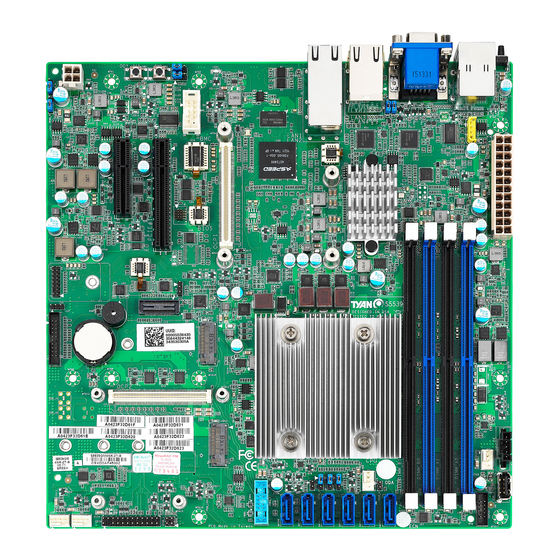
Page 9: Board Image
All manuals and user guides at all-guides.com 2.1 Board Image S5539GM4NR-D41-2T This picture is representative of the latest board revision available at the time of publishing. The board you receive may not look exactly like the above picture. http://www.tyan.com... -
Page 10: Block Diagram
All manuals and user guides at all-guides.com 2.2 Block Diagram S5539 Block Diagram http://www.tyan.com... -
Page 11: Motherboard Mechanical Drawing
All manuals and user guides at all-guides.com 2.3 Motherboard Mechanical Drawing http://www.tyan.com... -
Page 12: Board Parts, Jumpers And Connectors
All manuals and user guides at all-guides.com 2.4 Board Parts, Jumpers and Connectors This diagram is representative of the latest board revision available at the time of publishing. The board you receive may not look exactly like the above diagram. The DIMM slot numbers shown above can be used as a reference when reviewing the DIMM population guidelines shown later in the manual. - Page 13 All manuals and user guides at all-guides.com Motherboard Components Connectors 1. LAN port#5 (IPMI) and USB 3.0 ports 14. 4-pin Fan Connector(J24) 2. VGA Port & COM Port 15. 7-pin Vertical SATA3.0 Connector (SATA5) 3. LAN Port#3(LAN3)&LAN Port#4(LAN4) 16. 7-pin Vertical SATA3.0 Connector (SATA4) 4.
- Page 14 All manuals and user guides at all-guides.com SYS_FAN1/2/3/4_FAN: 4-Pin FAN Connector Signal +12V FAN_TACH FAN_PWM Use this header to connect the cooling fan to your motherboard to keep the system stable and reliable. Note: A 4-pin fan is required for fan speed control. FPIO: Front Panel Connector Signal...
- Page 15 All manuals and user guides at all-guides.com USB1: Vertical (Type_A) USB2.0 Connector Signal USBD- USBD+ Front Fan Connector (Reserved for Barebone) Signal Signal TACH1 TACH6 TACH2 TACH7 TACH3 TACH8 TACH4 TACH9 TACH5 TACH10 PWM2 PWM1 TACH11 SMB_DATA TACH12 SMB_CLK VCC3_AUX PWM3 SATA0~5 : 7-pin vertical SATA3.0 Connector(Blue)
- Page 16 All manuals and user guides at all-guides.com COM2: COM Header Signal Signal SOUT IPMB Connector Signal Signal BMC_SMB_DATA BMC_SMB_CLK 2PHD_3: Chassis Intrusion Header Signal BDX_INTRUDER_N Open (Default) Open: Use this header to disable the system chassis intrusion alarm. Short: Use this header to trigger the system chassis intrusion alarm.
- Page 17 All manuals and user guides at all-guides.com 3PHD_1: System RTC Clear CMOS set RST_SRTCR RST_RTCRST_N Ground ST_N Pin 1-2 Closed: Normal Mode (Default) Pin 2-3 Closed: BIOS Reset Mode Caution: The jumpers are only using for engineering debug. We don‟t suggest customers change the jumpers‟...
-
Page 18: Installing The Processor And Heatsink
® the latest list of validated Intel processors for this specific motherboard. NOTE: MiTAC is not liable for damage as a result of operating an unsupported configuration. Processor Installation (for Intel Broadwell-DE CPU) ® When you receive the motherboard, both Intel Broadwell-D processors and heat sinks have been installed in advance in the factory. -
Page 19: Tips On Installing Motherboard In Chassis
All manuals and user guides at all-guides.com 2.6 Tips on Installing Motherboard in Chassis Before installing your motherboard, make sure your chassis has the necessary motherboard support studs installed. These studs are usually metal and are gold in color. Usually, the chassis manufacturer will pre-install the support studs. If you are unsure of stud placement, simply lay the motherboard inside the chassis and align the screw holes of the motherboard to the studs inside the case. - Page 20 All manuals and user guides at all-guides.com Some chassis include plastic studs instead of metal. Although the plastic studs are usable, MiTAC recommends using metal studs with screws that will fasten the motherboard more securely in place. Below is a chart detailing what the most common motherboard studs look like and how they should be installed.
-
Page 21: Installing The Memory
All manuals and user guides at all-guides.com 2.7 Installing the Memory Before installing memory, ensure that the memory you have is compatible with the motherboard and processor. Check the TYAN Web site at http://www.tyan.com details of the type of memory recommended for your motherboard. ... - Page 22 All manuals and user guides at all-guides.com Recommended Memory Population Table (Single CPU) Single CPU Installed Quantity of memory installed √ √ √ √ CPU_DIMM_A0 √ √ √ CPU_DIMM_A1 √ √ CPU_DIMM_B0 CPU_DIMM_B1 √ NOTE: 1.√ indicates a populated DIMM slot. 2.
- Page 23 All manuals and user guides at all-guides.com NOTE 1: 1DPC => One dimm per channel NOTE 2: 2DPC => Two dimm per channel Physical Ranks are used to calculate DIMM Capacity. Supported DRAM Densities are 4Gb, 8Gb,16Gb,32Gb *Based on CPU model, for example QDF number QK8B(1.4GHz,Y0 stepping)can support 2400 speed http://www.tyan.com...
- Page 24 All manuals and user guides at all-guides.com Memory Installation Procedure Follow these instructions to install memory modules into the S5539. Unlock a DIMM socket by Press the retaining clip outwardly in the following illustration. Align the memory module with the socket,such that the DIMM NOTCH match the KEY SLOT on the socket.
-
Page 25: Attaching Drive Cables
All manuals and user guides at all-guides.com 2.8 Attaching Drive Cables Attaching SATA Cables The following illustrates how to make a SATA Cable connection. If you are in need of SATA/SAS cables or power adapters please contact your local sales representative. -
Page 26: Installing Add-In Cards
All manuals and user guides at all-guides.com 2.9 Installing Add-In Cards Before installing add-in cards, it‟s helpful to know if they are fully compatible with your motherboard. For this reason, we‟ve provided the diagrams below, showing the slots that may appear on your motherboard. Slot OCP1/2 (J8/J15): OCP Mezzanine card connector 2. -
Page 27: Connecting External Devices
All manuals and user guides at all-guides.com 2.10 Connecting External Devices Connecting external devices to the motherboard is an easy task. The motherboard supports a number of different interfaces through connecting peripherals. See the following diagrams for the details. LAN5 (dedicated for IPMI) VGA Port LAN4 (i210) -
Page 28: Installing The Power Supply
All manuals and user guides at all-guides.com 2.11 Installing the Power Supply There are One (1) power connectors on your S5539 motherboard. The S5539 supports EPS 12V power supply. PWR1: SSI 24-Pin Power Connector Signal Signal V3P3 V3P3 V3P3 -12V PS_ON# PWROK 5VSB... -
Page 29: Chapter 3: Bios Setup
All manuals and user guides at all-guides.com Chapter 3: BIOS Setup 3.1 About the BIOS The BIOS is the basic input/output system, the firmware on the motherboard that enables your hardware to interface with your software. The BIOS determines what a computer can do without accessing programs from a disk. - Page 30 Chipset section unless you are absolutely sure of what you are doing. The Chipset defaults have been carefully chosen either by MiTAC or your system manufacturer for best performance and reliability. Even a seemingly small change to the Chipset setup options may cause the system to become unstable or unusable.
-
Page 31: Main Menu
All manuals and user guides at all-guides.com 3.2 Main Menu In this section, you can alter general features such as the date and time. Note that the options listed below are for options that can directly be changed within the Main Setup screen. BIOS Information It displays BIOS related information. -
Page 32: Advanced Menu
All manuals and user guides at all-guides.com 3.3 Advanced Menu This section facilitates configuring advanced BIOS options for your system. Trusted Computing(optional function) Trusted Computing (TPM) settings. NOTE: If no TPM chipset is on, the Trusted Computing submenu will not appear. ACPI Settings System ACPI Parameters. - Page 33 All manuals and user guides at all-guides.com SIO Configuration System Super IO Chip parameters S5 RTC Wake Settings S5 RTC Wake Settings Serial Port Console Redirection Serial Port Console Redirection PCI Subsystem Settings PCI, PCI-X and PCI Express Settings CSM Configuration CSM Configuration, Enable/Disable Option ROM execution setting, etc USB Configuration USB Configuration Parameters.
- Page 34 All manuals and user guides at all-guides.com 3.3.1 Trusted Computing (optional function) NOTE: If no TPM chipset is on, the Trusted Computing submenu will not appear. Security Device Support Enable or disable BIOS support for security device. O.S. will not show Security device.
- Page 35 All manuals and user guides at all-guides.com 3.3.2 ACPI Settings Enable ACPI Auto Configuration Enable or disable BIOS ACPI Auto Configuration. Disabled / Enabled Enable Hibernation Enables or disables System ability to Hibernate (OS/S4 Sleep State). This option may not be effective with some OS. Disabled / Enabled http://www.tyan.com...
- Page 36 All manuals and user guides at all-guides.com 3.3.3 Hardware Health Configuration Auto Fan Control Auto Fan Control help. Disabled / Enabled NOTE: Auto Fan Control must be set to [Enable] PWM Minimal Duty Cycle menu will appear. PWM Minimal Duty Cycle PWM Minima Duty Cycle 30% Duty Cycle / 45% Duty Cycle / 60% Duty Cycle BMC Alert Beep...
- Page 37 All manuals and user guides at all-guides.com 3.3.3.1 Sensor Data Register Monitoring When you enter the Sensor Data Register Monitoring submenu, you will see the following dialog window pop out. Please wait 8~10 seconds. NOTE 1: SDR can not be modified. Read only. http://www.tyan.com...
- Page 38 All manuals and user guides at all-guides.com http://www.tyan.com...
- Page 39 All manuals and user guides at all-guides.com 3.3.4 Onboard Device Configuration Onboard LAN1 (X557) optional Enable/Disable Onboard LAN Devices Enabled / Disabled LAN1 OPROM Enable/Disable Load Option ROM For OnBoard LAN Enabled with PXE / Disabled Onboard LAN2 (X557) optional Enable/Disable OnBoard LAN Devices Enabled / Disabled LAN2 OPROM...
- Page 40 All manuals and user guides at all-guides.com LAN3 OPROM Select LAN3 oprom Enabled with iSCSI / Enabled with PXE / Disabled Onboard LAN4 (I210) Enable or disable the I210 Controller. Enabled / Disabled LAN4 OPROM Select LAN4 oprom Enabled with PXE / Disabled NOTE: The ISCSI function is only supported in LAN#3.
- Page 41 All manuals and user guides at all-guides.com 3.3.5 PCIe Slot Configuration PCIE Slot Configuration PCIE SAS Header Link Width PCIE SAS Header Link Width Seperate x4x4 Or Total x8 x4x4 / x8 PCIE Slot 1 Link Width x4x4 / x8 PCIE Slot Option ROM Setting OCP1 LAN Mezzanine Slot Enable/Disable Load Oprom for OCP PCIE Slot...
- Page 42 All manuals and user guides at all-guides.com PCIE Slot2 Enable/Disable Load Oprom for PCIE Slot Enabled / Disabled PCIE Slot Link Speed Configuration OCP1 LAN Mezzanine Slot OCP PCIE Slot Link Speed Configuration Auto / Gen1(2.5 GT/s) / Gen2(5 GT/s) / Gen3(8 GT/s) OCP2 SAS Mezzanine Slot PCLe Slot Link Speed Configuration (Gen1/Gen2/Gen3) Auto / Gen1(2.5 GT/s) / Gen2(5 GT/s) / Gen3(8 GT/s)
- Page 43 All manuals and user guides at all-guides.com 3.3.6 Watchdog Timer Configuration Watch Dog Mode Watch Dog Mode Help. Disabled / POST / OS / PowerON NOTE: Watch Dog Timer will appear when Watch Dog Mode is not set to [Disabled]. Watch Dog Timer Watch Dog Timer Help.
- Page 44 All manuals and user guides at all-guides.com 3.3.7 SIO Configuration Super IO Chip Read only. http://www.tyan.com...
- Page 45 All manuals and user guides at all-guides.com 3.3.7.1 Serial Port 1 Configuration Serial Port Enable or disable Serial Port (COM). Enabled / Disabled Device Settings Read only. Change Settings Select an optimal setting for Super IO Device. Auto / IO=3F8h; IRQ=4; / IO=3F8h, IRQ=3, 4, 5, 6, 7, 9, 10, 11, 12;...
- Page 46 All manuals and user guides at all-guides.com 3.3.7.2 Serial Port 2 Configuration Serial Port Enable or disable Serial Port (COM). Enabled / Disabled Device Settings Read only. Change Settings Select an optimal setting for Super IO Device. Auto / IO=3F8h; IRQ=4; / IO=3F8h, IRQ=3, 4, 5, 6, 7, 9, 10, 11, 12;...
- Page 47 All manuals and user guides at all-guides.com 3.3.8 S5 RTC Wake Settings Wake system from S5 Enable or disable system wake on alarm event. Select Fixed time, system will wake on the hr::min::sec specified. Select dynamic time, system will wake on the current time+ increase minute(s) Disabled / Fixed time / Dynamic time http://www.tyan.com...
- Page 48 All manuals and user guides at all-guides.com 3.3.9 Serial Port Console Redirection COM1 Console Redirection Console redirection enable or disable. Disabled / Enabled COM2 Console Redirection Console redirection enable or disable. Disabled / Enabled Serial Port for Out-Of-Band Management/Windows Emergency Services (EMS) Console Redirection Console redirection enable or disable.
- Page 49 All manuals and user guides at all-guides.com 3.3.9.1 Console Redirection Settings Terminal Type Emulation: ANSI: Extended ASCII charset. VT100: ASCII charset. VT100+: Extends VT100 to support color function keys, etc. VT-UTF8: Uses UTF8 encoding to map Unicode chars onto 1 or more bytes. VT-UTF8 / VT100 / VT100+ / ANSI Bits per Second Select serial port transmission speed.
- Page 50 All manuals and user guides at all-guides.com Stop Bits Stop bits indicate the end of a serial data packet. (A start bit indicates the beginning). The standard setting is 1 stop bit. Communication with slow devices may require more than 1 stop bit. 1 / 2 Flow Control Flow Control can prevent data loss from buffer overflow.
- Page 51 All manuals and user guides at all-guides.com 3.3.9.2 Legacy Serial Redirection Settings Legacy Serial Redirection Port Select a COM Port to display redirection of Legacy OS and Legacy OPROM Messages COM1 / COM2 http://www.tyan.com...
- Page 52 All manuals and user guides at all-guides.com 3.3.9.3 Serial Port for Out-Of-Band Management/Windows Emergency Services (EMS) Console Redirection Settings Out-of Band Mgmt Port Microsoft Windows Emergency Management Services (EMS) allows for remote management of a Windows Server OS through a serial port. COM1 Terminal Type VT-UTF8 is the preferred terminal type for out-of-band management.
- Page 53 All manuals and user guides at all-guides.com Flow Control Flow Control can prevent data loss from buffer overflow. When sending data, if the receiving buffers are full, a „stop‟ signal can be sent to stop the data flow. Once the buffers are empty, a „start‟...
- Page 54 All manuals and user guides at all-guides.com 3.3.10 PCI Subsystem Above 4G Decoding Enables or Disables 64bit capable Devices to be decoded in Above 4G Address Space(Only if System supports 64 bit PCI decoding). Enable / Disabled SR-IOV Supporting If system has SR-IOV capable PCIe devices, this option Enable or Disable Single root IO virtualization Support Enable / Disabled http://www.tyan.com...
- Page 55 All manuals and user guides at all-guides.com 3.3.10.1 PCI Express settings Maximum Payload Set maximum payload of PCI express device or allow system BIOS to select the value. Auto / 128 Bytes / 256 Bytes http://www.tyan.com...
- Page 56 All manuals and user guides at all-guides.com 3.3.11 CSM Configuration CSM support Enable/Disable CSM Support Enabled / Disabled Option ROM Messages Set display mode for Option ROM Force BIOS / Keep Current Network Controls the execution of UEFI and legacy PXE OpROM Do not launch / UEFI / legacy Storage Controls the execution of UEFI and legacy PXE OpROM...
- Page 57 All manuals and user guides at all-guides.com 3.3.12 USB Configuration Legacy USB Support Enable USB legacy support. AUTO option disables legacy support if no USB devices are connected. DISABLE option will keep USB devices available only for EFI applications. Enabled / Disabled / Auto XHCI Hand-off This is a workaround for OSes without XHCI hand-off support.
- Page 58 All manuals and user guides at all-guides.com USB transfer time-out The time-out value for Control, Bulk and Interrupt transfers. 20 sec / 10 sec / 5 sec / 1 sec Device reset time-out USB mass storage device Start Unit command time-out. 20 sec / 10 sec / 30 sec / 40 sec Device power-up delay Maximum time the device will take before it properly reports itself to the Host...
-
Page 59: Intel Rcsetup Menu
All manuals and user guides at all-guides.com 3.4 Intel RCSetup Menu Processor Configuration Displays and provides option to change the processor settings. Advanced Power Management Configuration Displays and provides option to change power management settings. Common RefCode Configuration Displays and provides option to change Common RefCode settings. Memory Configuration Displays and provides option to change Memory settings I/O Configuration... - Page 60 All manuals and user guides at all-guides.com Runtime Error Logging Displays and provides option to change Runtime Error Logging 3.4.1 Processor Configuration Hyper Threading (ALL) Enabled for Windows XP and Linux (OS optimized for Hyper Threading Technology) and disabled for other OS (OS not optimized for Hyper Threading Technology). When disabled only one thread Enable / Disabled Execute Disable Bit...
- Page 61 All manuals and user guides at all-guides.com Enable Intel TXT Support Enables Intel Trusted Execution technology Configuration. Please disable “EV DFX Features” when TXT is enabled. Enabled Disable Enables the vanderpool technology, take effect after reboot Enabled Disabled http://www.tyan.com...
- Page 62 All manuals and user guides at all-guides.com 3.4.1.1 CPU Socket 0 Configuration Read only http://www.tyan.com...
- Page 63 All manuals and user guides at all-guides.com http://www.tyan.com...
- Page 64 All manuals and user guides at all-guides.com 3.4.2 Advanced Power Management Configuration Power Technology Enable the power management features. Custom / Disabled / Energy Efficient NOTE: The items CPUP/C State Control are available only when Power Technology is set to [Custom]. http://www.tyan.com...
- Page 65 All manuals and user guides at all-guides.com 3.4.2.1 CPU P State Control EIST (P-states) When enabled,OS sets CPU frequency according load. When disabled, CPU frequency is set at max non-turbo. Enable Disabled Turbo Mode Turbo mode allows a CPU logical processor to execute a higher frequency when Enough power is available not exceed CPU defined limits.
- Page 66 All manuals and user guides at all-guides.com 3.4.2.2 CPU C State Control Package C State Limit C0/C1 state / C2 state / C6 (non Retention) state / C6 (Retention State) CPU C3 Report Enable/Disable CPU C3 (ACPI C2) report to OS. Recommended to be disabled Enable / Disable CPU C6 Report Enable/Disable CPU C6 (ACPI C3) report to OS.
- Page 67 All manuals and user guides at all-guides.com 3.4.3 Common RefCode Configuraion MMIOHBase MMIOH Base [63:32]; must be between 4032 - 4078 56T / 48T / 24T /16T / 4T MMIO High Size Select MMIO High Size 256G /128G / 512G /1024G Numa Enable or Disable none uniform Memory Access.
- Page 68 All manuals and user guides at all-guides.com 3.4.4 Memory Configuration Enforce POR Enable to enforce POR restrictions for DDR frequency and voltage programming Auto / Disabled http://www.tyan.com...
- Page 69 All manuals and user guides at all-guides.com 3.4.4.1 Memory Topology Configuration Read only http://www.tyan.com...
- Page 70 All manuals and user guides at all-guides.com 3.4.4.2 Memory Thermal Configuration Set Throttling Mode Configure Thermal throttling mode. Select OLTT or CLTT mode. Disabled / CLTT / OLTT http://www.tyan.com...
- Page 71 All manuals and user guides at all-guides.com 3.4.4.3 Memory RAS Configuration Correctable Error Threshold Correctable Error Threshold (1-32767) used for sparing, tagging, and leaky bucket. http://www.tyan.com...
- Page 72 All manuals and user guides at all-guides.com 3.4.5 I/O Configuration Submenu Read only http://www.tyan.com...
- Page 73 All manuals and user guides at all-guides.com ® 3.4.5.1 Intel VT for Directed I/O Configuration Submenu ® Intel VT for directed I/O (VT-d) ® Enable/Disable Intel I/O Virtualization Technology for Directed I/O(VT-d) by reporting the I/O device assignment to VMM through IMAR ACPI Tables. Disable / Enable http://www.tyan.com...
- Page 74 All manuals and user guides at all-guides.com 3.4.6 PCH Configuration http://www.tyan.com...
- Page 75 All manuals and user guides at all-guides.com 3.4.6.1 PCH Devices Configuration PCH State after G3 Select S0/S5 for ACPI state after a G3. S0 / S5 / Last State http://www.tyan.com...
- Page 76 All manuals and user guides at all-guides.com 3.4.6.2 PCH SATA Configuration http://www.tyan.com...
- Page 77 All manuals and user guides at all-guides.com SATA Controller Enable or Disable SATA Controller Disabled / Enabled Configure SATA as Indentify the SATA port is connected to Solid State Drive or Hard Disk Drive IDE / AHCI / RAID Support Aggressive Link Power Mana Enable or Disable Aggressive Link Power Mana Disabled / Enabled SATA Port 0/1/2/3/4/5...
- Page 78 All manuals and user guides at all-guides.com 3.4.7 USB Configuration xHCI Mode Mode of operation of xHCI controller. Auto / Smart Auto / Disabled http://www.tyan.com...
- Page 79 All manuals and user guides at all-guides.com 3.4.8 Miscellaneous Configuration Active Video Select active video type Onboard Device / Offboard Device http://www.tyan.com...
- Page 80 All manuals and user guides at all-guides.com 3.4.9 Runtime Error Logging Configuration System Errors System error enabling and logging setup option Disable / Enable http://www.tyan.com...
- Page 81 All manuals and user guides at all-guides.com 3.4.9.1 Memory Error Enabling Configuration Memory corrected Error enabling Enable/ disable Memory corrected errors Disable / Enable Spare interrupt Select SMI/CMCI/Error Pin for spare interrupt SMI / CMCI http://www.tyan.com...
-
Page 82: Server Management
All manuals and user guides at all-guides.com 3.5 Server Management Press <Enter> to change the SEL configuration. Enable/Disable interfaces to communicate with BMC. http://www.tyan.com... - Page 83 All manuals and user guides at all-guides.com 3.5.1 System Event Log SEL Components Change this to enable or disable all features of System Event Logging during boot. Disabled / Enabled Erase SEL Choose options for erasing SEL. No / Yes, on next reset / No, on every reset When SEL is Full Choose options for reactions to a full SEL.
- Page 84 All manuals and user guides at all-guides.com 3.5.2 BMC Network Configuration Lan Channel 1/2 Configuration Address Source Select the configure LAN channel parameters statically or dynamically (by BIOS or BMC). Unspecified option will not modify any BMC network parameters during BIOS phase.
-
Page 85: Security
All manuals and user guides at all-guides.com 3.6 Security Administrator Password Install or change the password. User Password Install or change the password. http://www.tyan.com... -
Page 86: Boot
All manuals and user guides at all-guides.com 3.7 Boot Bootup NumLock State Select the keyboard NumLock state. Off / On Quiet Boot Enable or disable Quiet Boot option. Disabled / Enabled Boot Option #1/Boot Option #2 Select the first boot device. Device Name / Disabled Wait For “ESC”... - Page 87 All manuals and user guides at all-guides.com New Boot Option Policy Controlls the placement of newly detected UEFI boot options Default / place first / place last 3.7.1 Delete Boot Option Configuration Delete Boot Option Sets the system boot order. Device Name / Select one to Delete http://www.tyan.com...
-
Page 88: Save & Exit
All manuals and user guides at all-guides.com 3.8 Save & Exit Save Changes and Exit Exit system setup after saving the changes. Discard Changes and Exit Exit system setup without saving any changes. Save Changes and Reset Reset the system after saving the changes. Discard Changes and Reset Reset system setup without saving any changes. - Page 89 All manuals and user guides at all-guides.com Save as User Defaults Save the changes done so far as User Defaults. Restore User Defaults Restore the User Defaults to all the setup options. Boot Override Device Name http://www.tyan.com...
-
Page 90: Chapter 4: Diagnostics
All manuals and user guides at all-guides.com Chapter 4: Diagnostics NOTE: if you experience problems with setting up your system, always check the following things in the following order: Memory, Video, CPU By checking these items, you will most likely find out what the problem might have been when setting up your system. -
Page 91: Amibios Post Code (Aptio)
All manuals and user guides at all-guides.com 4.2 AMIBIOS Post Code (Aptio) The POST code checkpoints are the largest set of checkpoints during the BIOS pre- boot process. The following table describes the type of checkpoints that may occur during the POST portion of the BIOS: Checkpoint Ranges Status Code Range Description... - Page 92 All manuals and user guides at all-guides.com SEC Error Codes 0x0C – 0x0D Reserved for future AMI SEC error codes 0x0E Microcode not found 0x0F Microcode not found SEC Phase None PEI Phase Status Code Description Progress Codes 0x10 PCI Core is started 0x11 Pre-memory CPU initialization is started 0x12...
- Page 93 All manuals and user guides at all-guides.com Status Code Description CPU post-memory initialization. Boot Strap Processor (BSP) 0x35 selection CPU post-memory initialization. System Management Mode (SMM) 0x36 initialization 0x37 Post-Memory North Bridge initialization is started. Post-Memory North Bridge initialization (North Bridge module 0x38 specific) Post-Memory North Bridge initialization (North Bridge module...
- Page 94 All manuals and user guides at all-guides.com Status Code Description S3 Resume Error Codes 0xE8 S3 Resume failed 0xE9 S3 Resume PPI not found 0xEA S3 Resume Boot Script error 0xEB S3 OS wake error 0xEC – 0xEF Reserved for future AMI error codes Recovery Progress Codes 0xF0 Recovery condition triggered by firmware (Auto recovery)
- Page 95 All manuals and user guides at all-guides.com Status Code Description 0x63 CPU DXE initialization is started. 0x64 CPU DXE initialization (CPU module specific) 0x65 CPU DXE initialization (CPU module specific) 0x66 CPU DXE initialization (CPU module specific) 0x67 CPU DXE initialization (CPU module specific) 0x68 PCI host bridge initialization 0x69...
- Page 96 All manuals and user guides at all-guides.com Status Code Description 0x9B USB Reset 0x9C USB Detect 0x9D USB Enable 0x9E -0x9F Reserved for future AMI codes 0xA0 IDE initialization is started 0xA1 IDE Reset 0xA2 IDE Detect 0xA3 IDE Enable 0xA4 SCSI initialization is started.
- Page 97 All manuals and user guides at all-guides.com Status Code Description 0xD5 No Space for Legacy Option ROM 0xD6 No Console Output Devices are found. 0xD7 No Console Input Devices are found. 0xD8 Invalid password 0xD9 Error loading Boot Option (LoadImage returned error) 0xDA Boot Option is failed (StartImage returned error).
-
Page 98: Appendix I: Fan And Temp Sensors
All manuals and user guides at all-guides.com Appendix I: Fan and Temp Sensors This section aims to help readers identify the locations of some specific FAN and Temp Sensors on the motherboard. A table of BIOS Temp sensor name explanation is also included for readers‟ reference. NOTE: The red dot indicates the sensor. - Page 99 All manuals and user guides at all-guides.com BIOS Temp Sensor Name Explanation: CPU_DTS_Temp Temperature of the CPU Digital Temperature Sensor CPU_PECI_Value Temperature of the CPU Platform Environment Control Interface SYS_ Air_Inlet Temperature of the SYS_Air_Inlet Area M/B_Air_Inlet Temperature of the MB_Air_ Inlet Area CPU0_DIMM_A0 Temperature of CPU0 DIMM A0 Slot CPU0_DIMM_A1...
- Page 100 All manuals and user guides at all-guides.com NOTE http://www.tyan.com...
-
Page 101: Glossary
All manuals and user guides at all-guides.com Glossary ACPI (Advanced Configuration and Power Interface): a power management specification that allows the operating system to control the amount of power distributed to the computer‟s devices. Devices not in use can be turned off, reducing unnecessary power expenditure. - Page 102 All manuals and user guides at all-guides.com Bus: a data pathway. The term is used especially to refer to the connection between the processor and system memory, and between the processor and PCI or ISA local buses. Bus mastering: allows peripheral devices and IDEs to access the system memory without going through the CPU (similar to DMA channels).
- Page 103 All manuals and user guides at all-guides.com DRAM (Dynamic RAM): widely available, very affordable form of RAM which looses data if it is not recharged regularly (every few milliseconds). This refresh requirement makes DRAM three to ten times slower than non-recharged RAM such as SRAM.
- Page 104 All manuals and user guides at all-guides.com I/O (Input/Output): the connection between your computer and another piece of hardware (mouse, keyboard, etc.) IRQ (Interrupt Request): an electronic request that runs from a hardware device to the CPU. The interrupt controller assigns priorities to incoming requests and delivers them to the CPU.
- Page 105 All manuals and user guides at all-guides.com RAID (Redundant Array of Independent Disks): a way for the same data to be stored in different places on many hard drives. By using this method, the data is stored redundantly and multiple hard drives will appear as a single drive to the operating system.
- Page 106 All manuals and user guides at all-guides.com Standby mode: in this mode, the video and hard drives shut down; all other devices continue to operate normally. UltraDMA-33/66/100: a fast version of the old DMA channel. UltraDMA is also called UltraATA. Without a proper UltraDMA controller, your system cannot take advantage of higher data transfer rates of the new UltraDMA/UltraATA hard drives.
-
Page 107: Technical Support
All manuals and user guides at all-guides.com Technical Support If a problem arises with your system, you should first turn to your dealer for direct support. Your system has most likely been configured or designed by them and they should have the best idea of what hardware and software your system contains. - Page 108 All manuals and user guides at all-guides.com NOTE: A receipt or copy of your invoice marked with the date of purchase is required before any warranty service can be rendered. You may obtain service by calling the manufacturer for a Return Merchandise Authorization (RMA) number.
Need help?
Do you have a question about the TYAN S5539 and is the answer not in the manual?
Questions and answers