Table of Contents
Advertisement
Quick Links
Copyright
Copyright © 2023 MITAC COMPUTING TECHNOLOGY CORPORATION. All rights
reserved. No part of this manual may be reproduced or translated without prior
written consent from MITAC COMPUTING TECHNOLOGY CORPORATION.
Trademark
All registered and unregistered trademarks and company names contained in this
manual are property of their respective owners including, but not limited to the
following.
®
TYAN
is a trademark of MITAC COMPUTING TECHNOLOGY CORPORATION.
®
AMD
is a trademark of AMD
Intel
®
is a trademark of Intel
AMI, AMI BIOS are trademarks of AMI Technologies.
®
Microsoft
, Windows
®
Nuvoton
is a trademark of Nuvoton Technology Corporation.
Notice
Information contained in this document is furnished by MITAC COMPUTING
TECHNOLOGY CORPORATION and has been reviewed for accuracy and reliability
prior to printing. MITAC assumes no liability whatsoever, and disclaims any express
or implied warranty, relating to sale and/or use of TYAN
or warranties relating to fitness for a particular purpose or merchantability. MITAC
retains the right to make changes to product descriptions and/or specifications at
any time, without notice. In no event will MITAC be held liable for any direct or
indirect, incidental or consequential damage, loss of use, loss of data or other
malady resulting from errors or inaccuracies of information contained in this
document.
S7130
Version 1.0b
®
Corporation.
®
Corporation.
®
are trademarks of Microsoft Corporation.
http://www.tyan.com
®
products including liability
1
Advertisement
Table of Contents

Related Manuals for MiTAC TYAN S7130


Summary of Contents for MiTAC TYAN S7130
- Page 1 In no event will MITAC be held liable for any direct or indirect, incidental or consequential damage, loss of use, loss of data or other malady resulting from errors or inaccuracies of information contained in this document.
- Page 2 http://www.tyan.com...
-
Page 3: Table Of Contents
Contents Before you begin… ..................4 Chapter 1: Instruction ................5 1.1 Congratulations ................. 5 1.2 Hardware Specifications ..............5 1.3 Software Specifications ..............7 Chapter 2: Board Installation ..............9 2.1 Board Image ..................10 ... -
Page 4: Before You Begin
Before you begin… Check the box contents! The retail motherboard package should contain the following: 1 x S7130 Motherboard 2 x SATA Signal Cable 2 x XCC CPU Carrier 2 x MCC CPU Carrier 1 x IO Shielding 1 x S7130 Quick reference guide IMPORTANT NOTE: Sales sample may not come with the accessory listed above. -
Page 5: Chapter 1: Instruction
TYAN ® products as well as all the supporting documentation, FAQs, Drivers and BIOS upgrades. 1.2 Hardware Specifications TYAN S7130 (S7130GM2NR-2T) Q'ty / Socket Type (2) LGA4677 Supported CPU Series 4th Gen. Intel Xeon Scalable Processors / Processor 5th Gen. - Page 6 Controller Intel X710-AT2 Realtek RTL8211F Connector (10) SATA Controller Intel C741 Storage SATA Speed 6Gb/s RAID RAID 0/1/10/5 (Intel RSTe) Storage NVMe Connector (M.2) (1) 2280 (PCIe x4 interface) Connector type D-Sub 15-pin Graphic VGA Resolution Up to 1920x1200 Chipset Aspeed AST2600 (1) USB2.0 port ( Type-A ) / (2) USB3.1 Gen.1 ports / (1) USB3.1 Gen.1 header...
-
Page 7: Software Specifications
FCC (SDoC) Class A CE (DoC) Class A Regulation Class A VCCI Class A Operating Temp. 10° C ~ 35° C (50° F~ 95° F) Operating Non-operating Temp. - 40° C ~ 70° C (-40° F ~ 158° F) Environment In/Non-operating Humidity 90%, non-condensing at 35°... - Page 8 NOTE http://www.tyan.com...
-
Page 9: Chapter 2: Board Installation
Unplug the power from your computer power supply and then touch a safely grounded object to release static charge (i.e. power supply case). For the safest conditions, MITAC recommends wearing a static safety wrist strap. (2) Hold the motherboard by its edges and do not touch the bottom of the board, or flex the board in any way. -
Page 10: Board Image
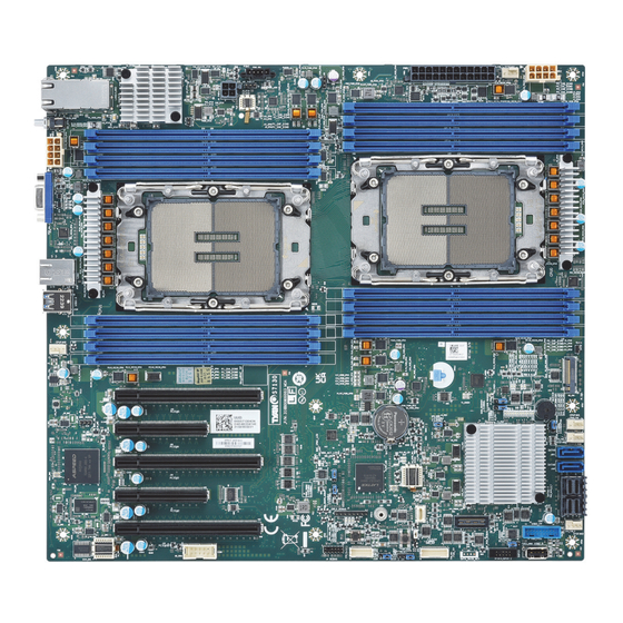
2.1 Board Image S7130 This picture is representative of the latest board revision available at the time of publishing. The board you receive may not look exactly like the above picture. http://www.tyan.com... -
Page 11: Block Diagram
2.2 Block Diagram S7130 Block Diagram http://www.tyan.com... -
Page 12: Mainboard Mechanical Drawing
2.3 Mainboard Mechanical Drawing http://www.tyan.com... -
Page 13: Board Parts, Jumpers And Connectors
2.4 Board Parts, Jumpers and Connectors This diagram is representative of the latest board revision available at the time of publishing. The board you receive may not look exactly like the above diagram. But for the DIMM number please refer to the above placement for memory installation. For the latest board revision, please visit our web site at http://www.tyan.com. - Page 14 Jumpers & Connectors Connectors 1. X710 LAN Connector (J511) 9. SATA 0-7 Connector (PCH_SATA_0_7) 2. 8-pin, CPU1 and CPU1 MEM Power 10. SATA 8 Connector (J107) Connector (12V input) (PW2) 3. VGA Connector (VGA_1) 11. SATA 9 Connector (J210) 4. IPMI LAN Connector (J133) 12.
- Page 15 Slots Buttons A CPU0 PCIE 1 x16 slot (J10) ID LED and Button (IDLED_BTN1) B CPU1 PCIE 2 x8 slot (J9) II Power Button (PWR_BTN1) C CPU1 PCIE 3 x16 slot (J34) III Reset Button (RST_BTN1) D CPU0 PCIE 4 x8 slot (J20) E CPU0 PCIE 5 x16 slot (J40) Jumper Legend OPEN - Jumper OFF...
- Page 16 CPU0_FAN, CPU1_FAN, SYS_FAN1~3: 4-pin FAN Connector Signal P12V FAN_TACH FAN_PWM Use this header to connect the cooling fan to your motherboard to keep the system stable and reliable. FPIO_1: Front Panel Pin Header Signal Signal FP_PW_LED_PW VCC_FPB (P3V3_AUX) FP_ID_LED_PW FP_PW_LED_GND FP_ID_LED_N HDD_LED_PW BMC_HW_FAULT_N...
- Page 17 USB3_FPIO1: Front USB3.1 Gen1 Header Signal Signal USB3_N1_RX_FPB USB3_P1_RX_FPB USB3_N0_RX_FPB USB3_P0_RX_FPB USB3_N1_TX_C_FPB USB3_P1_TX_C_FPB USB3_N0_TX_C_FPB USB3_P0_TX_C_FPB USB2_N4_FPB_R USB2_P4_FPB_R USB2_N6_FPB_R USB3_FPB_OC_N_R USB2_P6_FPB_R FAN_HD1: Fan Connector (Reserved for Barebone) Signal Signal TACH1 TACH6 TACH2 TACH7 TACH3 TACH8 TACH4 TACH9 TACH5 TACH10 PWM_FRONT3 PWM_FRONT12 TACH11 FAN_SDA TACH12...
- Page 18 HD_COM1: COM Port Header Signal Signal COM1_DCD COM1_DSR COM1_RXD COM1_RTS COM1_TXD COM1_CTS COM1_DTR COM1_NRI IDLED_BTN1: ID LED Button with LED Pin1,2 Pin3,4 Pin5 Pin6 FP_IDLED_BTN_N REAR_ID_LED_N REAR_IDLED_PW PWR_BTN1: Power Button Signal Signal PWR_BTN_N RST_BTN1: Reset Button Signal Signal RST_BTN_N J1_PCH: BIOS Recovery Mode Jumper Pin1 Pin2 Pin3...
- Page 19 J3_PCH: ME Recovery Jumper Pin1 Pin2 Pin3 10K-Pull hi FM_ME_RCVR_N 1K-Pull down (Default) Pin1-2 closed: Normal Mode Pin2-3 closed: ME Recovery J4_PCH: Manufacture Mode Jumper Pin1 Pin2 Pin3 1K-Pull hi FM_MFG_MODE 10K-Pull down Pin1-2 closed: MFG DISABLE (Default) Pin2-3 closed: MFG ENABLE J5_PCH: BIOS ADVANCE FUNCTIONS Jumper Pin1 Pin2...
- Page 20 J14: System Buzzer Jumper Pin1 Pin2 Pin3 Pin4 VCC5_BZ BUZ_1 BUZ_2 (Default) Pin3-4 closed: Normal Mode Pin2-3 closed: Disable PC Beep Pin1-4 closed: Use the external speaker http://www.tyan.com...
-
Page 21: Led Definitions
2.5 LED Definitions http://www.tyan.com... - Page 22 Signal P3V3_STBY State Description The LED shuts off when the Heart Beat D1_BMC BMC controller cannot be detected or properly initiated. The LED blinks per second to Green indicate that the BMC controller is working normally. Signal P3V3_AUX State Description CPLD The LED shuts off when the Heart Beat...
- Page 23 Signal P3V3_AUX PSU Alert State Description PSMI_LED1 The LED shuts off when the PSU is normal. The LED lights up when the PSU Orange is abnormal. Signal P3V3 State Description ERROR0 System working normally. Hardware correctable error. Signal P3V3 ERROR1 State Description System working normally.
-
Page 24: Installing The Processor And Heat Sink
Specifications on page 5. Check our website at http://www.tyan.com for latest processor support. NOTE: MITAC TYAN is not liable for damage as a result of operating an unsupported configuration. Processor Installation for Intel LGA4677 Socket Follow the steps below to install the processors and heat sinks. - Page 25 1. Align the Air Flow arrow on top of the heatsink with the rear I/O ports of the system. Then install the carrier on the bottom of the heatsink until the latches are snapped under the edge of the heatsink. Make sure the triangle mark on the carrier is pointing to the same direction as the Air Flow arrow on the heatsink.
- Page 26 4. Carefully flip the heatsink assembly. Align the heatsink with the CPU socket by the guide pins. Make also sure that the triangle edge of the carrier is aligned correctly with the triangle mark on the CPU socket. Then place the heatsink assembly onto the top of the CPU socket.
- Page 27 7. Connect the heatsink power cable to the mainboard connector. NOTE: A new heatsink comes with pre-applied thermal grease. Once the heatsink has been removed from the processor, you need to clean the processor and heatsink using an alcohol solvent. Then apply new thermal grease before reinstalling the heatsink.
-
Page 28: Tips On Installing Motherboard In Chassis
Some chassis include plastic studs instead of metal. Although the plastic studs are usable, MITAC recommends using metal studs with screws that will fasten the motherboard more securely in place. Below is a chart detailing what the most common motherboard studs look like and how they should be installed. - Page 29 http://www.tyan.com...
-
Page 30: Installing The Memory
2.8 Installing the Memory Before installing memory, ensure that the memory you have is compatible with the http://www.tyan.com motherboard and processor. Check the TYAN Web site at for details of the type of memory recommended for your motherboard. Supports 2,048GB RDIMM/RDIMM-3DS DDR5 5600/4800 (Follow latest Intel DDR5 Memory POR) ... - Page 31 Recommended Memory Population Table Quantity of memory installed Single CPU Installed (Reference Intel Memory Population #610826) √ P0_CHA_DIM0 √ √ √ √ √ √ P0_CHB_DIM0 √ √ √ √ √ P0_CHC_DIM0 √ √ √ √ √ √ P0_CHD_DIM0 √ √ √...
- Page 32 Quantity of memory installed Dual CPU Installed (Reference Intel Memory Population #610826) √ P0_CHA_DIM0 √ √ √ √ √ √ P0_CHB_DIM0 √ √ √ √ √ P0_CHC_DIM0 √ √ √ √ √ √ P0_CHD_DIM0 √ √ √ √ √ P0_CHE_DIM0 √...
- Page 33 Memory Installation Procedure Follow these instructions to install memory modules into the S7130. Unlock the clips as shown in the illustration. Insert the memory module firmly into the socket by gently pressing down until it sits flush with the socket. Lock the clips to secure the memory module into place.
-
Page 34: Attaching Drive Cables
2.9 Attaching Drive Cables Attaching Serial ATA Cables S7130 is equipped with ten (10) Serial ATA (SATA) channel. Connections for the drives are very simple. There is no need to set Master/Slave jumpers on SATA drives. If you are in need of SATA/SAS cables or power adapters please contact your place of purchase. -
Page 35: Installing Add-In Cards
2.10 Installing Add-In Cards Before installing add-in cards, it’s helpful to know if they are fully compatible with your motherboard. For this reason, we’ve provided the diagrams below, showing the slots that may appear on your motherboard. Simply find the appropriate slot for your add-in card and insert the card firmly. Do not force any add-in cards into any slots if they do not seat in place. -
Page 36: Connecting External Devices
2.11 Connecting External Devices Connecting external devices to the motherboard is an easy task. The motherboard supports a number of different interfaces through connecting peripherals. See the following diagrams for the details. NOTE: Peripheral devices can be plugged straight into any of these ports but software may be required to complete the installation. - Page 37 X710-AT2 100 Mbps / 1 Gbps / 10 Gbps LAN Link/Activity LED Scheme Description Left LED (Link/Activity) Right LED (Speed) No Link Link Solid Green 100 Mbps Active Blinking Green Link Solid Green Solid Yellow 1 Gbps Active Blinking Green Solid Yellow Link Solid Yellow...
-
Page 38: Installing The Power Supply
2.12 Installing the Power Supply There are four (4) power connectors on your S7130 motherboard. The S7130 supports EPS 12V power supply. NOTE: You must unplug the power supply before plugging the power cables to motherboard connectors. Warning: The mainboard supports up to 270W CPU TDP with the use of 16AWG... -
Page 39: Finishing Up
J6: 4-Pin PCIE Slots Power Connector Pin1 Pin2 Pin3 Pin4 P12V_IN P12V_IN 2.13 Finishing Up Congratulations on making it this far! You have finished setting up the hardware aspect of your computer. Before closing up your chassis, make sure that all cables and wires are connected properly, especially IDE cables and most importantly, jumpers. -
Page 40: Chapter 3: Bios Setup
Chapter 3: BIOS Setup 3.1 About the BIOS The BIOS is the basic input/output system, the firmware on the motherboard that enables your hardware to interface with your software. The BIOS determines what a computer can do without accessing programs from a disk. The BIOS contains all the code required to control the keyboard, display screen, disk drives, serial communications, and a number of miscellaneous functions. - Page 41 Chipset section unless you are absolutely sure of what you are doing. The Chipset defaults have been carefully chosen either by MITAC or your system manufacturer for best performance and reliability. Even a seemingly small change to the Chipset setup options may cause the system to become unstable or unusable.
-
Page 42: Main Menu
3.2 Main Menu In this section, you can alter general features such as the date and time. Note that the options listed below are for options that can directly be changed within the Main Setup screen. System Language Choose the system default language. English / Simplified Chinese / Japanese System Date Set the Date. -
Page 43: Advanced Menu
3.3 Advanced Menu This section facilitates configuring advanced BIOS options for your system. NOTE: This is a sample screenshot of the Advanced Menu. The HII network drivers displayed here depend on the card(s) you installed and the functions you enabled. Network Stack Configuration Network Stack Settings. - Page 44 Super IO Configuration System Super IO Chip Parameters. Hardware Health Configuration Hardware health Configuration Parameters. PCI Subsystem Settings PCI, PCI-X and PCI Express Settings. NVMe Configuration NVMe Devices Information. Trusted Computing Trusted Computing Settings. CSM Computing Enable/Disable, Option ROM execution settings, etc. Redfish Host Interface Settings Redfish Host Interface Parameters.
- Page 45 3.3.1 Network Stack Configuration NOTE: The BIOS will automatically read the onboard LAN controller. Network Stack Enable/Disable UEFI Network Stack. Disabled / Enabled NOTE: The following items are available when Network Stack is set to [Enabled]. Ipv4 PXE Support Enable Ipv4 PXE Boot Support. If disabled IPv4 PXE boot support will not be available.
- Page 46 Ipv6 HTTP Support Enable Ipv6 HTTP Boot Support. If disabled IPV6 HTTP boot support will not be available. Disabled / Enabled PXE boot wait time Wait time to press ESC key to abort the PXE boot. Media detect count Number of times the presence of media will be checked. Use either +/- or numeric keys to set the value.
- Page 47 3.3.2 S5 RTC Wake Settings Wake system from S5 Enable or disable System wake on alarm event. Select FixedTime, system will wake on the hr::min::sec specified. Select DynamicTime, system will wake on the current time + Increase minute(s). Disabled / Fixed Time / Dynamic Time When Wake system from S5 is set to [Fixed Time] Wake up hour Select 0-23.
- Page 48 3.3.3 Serial Port Console Redirection Console Redirection / Console Redirection EMS Console redirection enable or disable. Disabled / Enabled Legacy Console Redirection Settings Legacy Console redirection settings. Console Redirection Settings The settings specify how the host computer (which the user is using) will exchange data.
- Page 49 3.3.3.1 COM1 Console Redirection Settings Terminal Type Emulation: ANSI: Extended ASCII char set. VT100: ASCII char set. VT100+: Extends VT100 to support color, function keys, etc. VT-UTF8: Uses UTF8 encoding to map Unicode chars onto 1 or more bytes. VT100+ / VT100 / VT-UTF8 / ANSI Bits per Second Select serial port transmission speed.
- Page 50 Stop Bits Stop bits indicate the end of a serial data packet. (A start bit indicates the beginning). The standard setting is 1 stop bit. Communication with slow devices may require more than 1 stop bit. 1 / 2 Flow Control Flow Control can prevent data loss from buffer overflow.
- Page 51 3.3.3.2 Legacy Console Redirection Settings Legacy Serial Redirection Port Select a COM port to display redirection of Legacy OS and Legacy OPROM Messages. COM1 Resolution On Legacy OS, the Number of Rows and Columns supported redirection. 80x24 / 80x25 Redirect After POST When BootLoader is selected, then Legacy Console Redirection is disabled before booting to legacy OS, When Always Enable is selected, then Legacy Console Redirection is enabled for legacy OS.
- Page 52 3.3.3.3 Serial Port for Out-Of-Band Management/Windows Emergency Services (EMS) Console Redirection Settings Out-of-Band Mgmt Port Microsoft Windows Emergency Management Services (EMS) allows for remote management of a Windows Server OS through a serial port. COM1 Terminal Type VT-UTF8 is the preferred terminal type for out-of-band management. The next best choice is VT100+ and then VT100.
- Page 53 Flow Control Flow Control can prevent data loss from buffer overflow. When sending data, if the receiving buffers are full, a ‘stop’ signal can be sent to stop the data flow. Once the buffers are empty, a ‘start’ signal can be sent to restart the flow. Hardware flow control uses two wires to send start/stop signal.
- Page 54 3.3.4 PCIe Device Configuration http://www.tyan.com...
- Page 55 3.3.4.1 Option ROM Dispatch Policy LAN1 Option ROM Enable or Disable LAN1 Option ROM Enabled / Disabled LAN2 Option ROM Enable or Disable LAN2 Option ROM Enabled / Disabled PCIE#1~5 Option ROM Enable or Disable Option ROM execution for selected Slot. Enabled / Disabled http://www.tyan.com...
- Page 56 3.3.5 USB Configuration Legacy USB Support Enables USB legacy support. AUTO option disables legacy support if no USB devices are connected. DISABLE option will keep USB devices available only for EFI applications. Disabled / Enabled / Auto XHCI Hand-off This is a workaround for OSes without XHCI hand-off support. The XHCI ownership change should be claimed by XHCI driver.
- Page 57 USB transfer time-out The time-out value for Control, Bulk and Interrupt transfers. 1 sec / 5 sec / 10 sec / 20 sec Device reset time-out USB mass storage device Start Unit command time-out. 10 sec / 20 sec / 30 sec / 40 sec Device power-up delay Maximum time the device will take before it properly reports itself to the Host Controller.
- Page 58 3.3.6 Onboard Device Configuration Onboard VGA Enable/Disable ASPEED VGA. Enabled / Disabled LAN1 & LAN2 (X710) LAN Enable/Disable control function. Enabled / Disabled Primary Display Select active Video type. Onboard / External NMI Function Enable or Disable NMI function. Enabled / Disabled Chassis Intrusion Detection Enabled: When a chassis open event is detected, the BIOS will display the event.
- Page 59 3.3.7 Super IO Configuration Serial Port 1 Configuration Set Parameters of Serial Port 1 (COMA). http://www.tyan.com...
- Page 60 3.3.7.1 Serial Port 1 Configuration Serial Port Enable or disable Serial Port (COM). Enabled / Disabled Device Settings Read only. Change Settings Select an optimal setting for Super IO Device. Auto / IO=3F8h; IRQ=4; / IO=2F8h, IRQ=4; / IO=3E8h, IRQ=4; / IO=2E8h, IRQ=4;...
- Page 61 3.3.8 Hardware Health Configuration Fan Speed Control Fan Speed Control. Manual / Full Speed PWM Minimal Duty Cycle PWM Minimal Duty Cycle (%).This item is available when Fan Speed Control is set to [Manual]. BMC Alert Beep Enable/Disable BMC Alert Beep. On / Off PMBus support PMBus Support.
- Page 62 3.3.8.1 Sensor Data Register Monitoring http://www.tyan.com...
- Page 63 NOTE: SDR can not be modified. Read only. http://www.tyan.com...
- Page 64 3.3.9 PCI Subsystem Settings Above 4G Decoding Enables or Disables 64bit capable Devices to be Decoded in Above 4G Address Space (Only if System Supports 64 bit PCI Decoding). Enabled / Disabled SR-IOV Support If system has SR-IOV capable PCIe Devices, this option Enables or Disables Single Root IO Virtualization Support.
- Page 65 3.3.9.1 PCI Express Settings Max Payload Set Maximum Payload of PCI Express Device or allow System BIOS to select the value. Auto / 128 Bytes / 256 Bytes / 512 Bytes / 1024 Bytes / 2048 Bytes / 4096 Bytes http://www.tyan.com...
- Page 66 3.3.10 NVMe Configuration This page shows the Device Name you installed. Press Enter to read the device information. If no NVME device is installed, it shows no NVME device is found. Read only. http://www.tyan.com...
- Page 67 3.3.11 Trusted Computing Security Device Support Enables or Disables BIOS support for security device. O.S. will not show Security Device. TCG EFI protocol and INT1A interface will not be available. Enabled / Disabled http://www.tyan.com...
- Page 68 3.3.12 CSM Configuration CSM support Enable/Disable CSM Support Enabled / Disabled NOTE: The following items are available when CMS support is set to [Enabled]. Option ROM Messages Set display mode for Option ROM Force BIOS / Keep Current Network Controls the execution of UEFI and Legacy PXE OpROM UEFI / Legacy Storage Controls the execution of UEFI and Legacy Storage OpROM...
- Page 69 Video Controls the execution of UEFI and Legacy Video OpROM UEFI / Legacy Other PCI devices Determines OpRom execution policy for devices other than network, storage, or video UEFI / Legacy http://www.tyan.com...
- Page 70 3.3.13 Redfish Host Interface Settings Redfish Enable/Disable AMI Redfish. Enabled / Disabled BMC Redfish Version / BIOS Redfish Version Read only. IP Address Enter IP address. IP Mask Address Enter IP Mask address. IP Port Enter IP Port. http://www.tyan.com...
- Page 71 3.3.14 T1s Auth Configuration Server CA Configuration Press <Enter> to configure Server CA. Client Cert Configuration Press <Enter> to configure Client Cert. http://www.tyan.com...
- Page 72 3.3.14.1 Server CA Configuration Enroll Cert Press <Enter> to enroll cert. Delete Cert Press <Enter> to delete cert. http://www.tyan.com...
- Page 73 3.3.14.1.1 Enroll Cert Enroll Cert Using File Enroll Cert Using File. Cert GUID Input digit character in 11111111-2222-3333-4444-1234567890ab format. Commit Changes and Exit Commit Changes and Exit. Discard Changes and Exit Discard Changes and Exit. http://www.tyan.com...
- Page 74 3.3.14.1.2 Delete Cert XXXXX GUID for CERT. Disabled / Enabled http://www.tyan.com...
- Page 75 3.3.15 iSCSI Configuration Please follow the instructions to initiate the iSCSI function. Step 1. Select Advanced CSM Configuration Network [UEFI]. Step 2. Select Advanced Network Stack Configuration Network Stack [Enabled] Step 3. Save changes and reboot. Host iSCSI Configuration Host iSCSI Configuration http://www.tyan.com...
- Page 76 3.3.15.1 Host iSCSI Configuration iSCSI Initiator Name The worldwide unique name of iSCSI Initiator. Only IQN format is accepted. Enter [iqn.xxx]. xxx ranges from 4 to 223. For example: http://www.tyan.com...
- Page 77 Add an Attempt Add an Attempt. Delete Attempts Delete one or more attempts. Change Attempt Order Change the order of Attempts using +/- keys. Use arrow keys to select the attempt then press +/- to move the attempt up/down in the attempt order list. http://www.tyan.com...
- Page 78 3.3.15.1.1 Add an Attempt The screen shows the network protocols installed. If no network protocols are installed, the screen displays the message “Necessary network protocols are not available to retrieve….” MAC xx:xx:xx:xx:xx:xx (Intel® Ethernet Network Adapter) PFA: Bus 184 / Dev 0 / Func 0. http://www.tyan.com...
- Page 79 3.3.15.1.1.1 MAC XXX Intel® Ethernet Network Adapter iSCSI Attempt Name The human name defined for this attempt. Maximum length is up to 12 characters. Attempt 1 / Attempt # iSCSI Mode Disabled, Enabled, Enabled for MPIO. Disabled / Enabled / Enabled for MPIO Internet Protocol Initiator IP address is system assigned in IP6 mode.
- Page 80 Connection Establishing Timeout The timeout value in milliseconds. The minimum value is 100 milliseconds and the maximum is 20 seconds. Configure ISID OUI-format ISID in 6 bytes, default value is derived from MAC address. Only last 3 bytes are configurable. Example: update 0ABBCCDDEEFF to OABBCCF07901 by input F07901.
- Page 81 3.3.15.1.2 Delete Attempts Commit Changes and Exit Commit Changes and Exit. Discard Changes and Exit Discard Changes and Exit. http://www.tyan.com...
- Page 82 3.3.15.1.3 Change Attempt Order Commit Changes and Exit Commit Changes and Exit. Discard Changes and Exit Discard Changes and Exit. http://www.tyan.com...
- Page 83 3.3.16 VLAN Configuration (MAC:xxxxxxxxxxxx) Enter Configuration Menu Press ENTER to enter configuration menu for VLAN configuration. http://www.tyan.com...
- Page 84 3.3.16.1 Enter Configuration Menu VLAN ID VLAN ID of new VLAN or existing VLAN, valid value is 0~4094. Priority 802.1Q Priority, valid value is 0~7. Add VLAN Create a new VLAN or update existing VLAN. Remove VLAN Remove selected VLANs. http://www.tyan.com...
- Page 85 3.3.17 MAC:xxxxxxxxxxxx - IPv4 Network Configuration Configured Indicate whether network address configured successfully or not. Disabled / Enabled Save Changes and Exit Save Changes and Exit. http://www.tyan.com...
- Page 86 3.3.18 MAC:xxxxxxxxxxxx - IPv6 Network Configuration Enter Configuration Menu Press ENTER to enter configuration menu for IPv6 configuration. http://www.tyan.com...
- Page 87 3.3.18.1 Enter Configuration Menu Interface ID The 64 bit alternative interface ID for the device. The string is colon separated, e.g. ff:dd:88:66:cc:1:2:3 xx:xx:x:xx:xx:xx:xx:xx DAD Transmit Count The number of consecutive Neighbor Solicitation messages sent while performing Duplicate Address Detection on a tentative address. A value of zero indicates that Duplicate Address Detection is not performed.
- Page 88 Save Changes and Exit Save Changes and Exit. http://www.tyan.com...
- Page 89 3.3.18.1.1 Advanced Configuration New IPv6 address Manual IP address can only be configured under manual policy. Separate the IP address with blank space to configure more than one address. e.g. 2002::1/64 2002::2/64 New Gateway addresses Gateway IP address can only be configured under manual policy. e.g. 2002::3. Separate the IP address with blank space to configure more than one address.
- Page 90 3.3.19 Intel® Ethernet Network Adapter – xx:xx:xx:xx:xx:xx Firmware Image Properties View device firmware version information. NIC Configuration Click to configure the network device port. Blink LEDs Blink LEDs for a duration up to 15 seconds. http://www.tyan.com...
- Page 91 3.3.19.1 Firmware Image Properties Option ROM version / Unique NVM/EEPROM ID / NVM Version Read only. http://www.tyan.com...
- Page 92 3.3.19.2 NIC Configuration Link Speed Specifies the port speed used for the selected boot protocol. Auto Negotiated / 10 Mbps Half / 10Mbps Full / 100Mbps Half / 100Mbps Full Wake On LAN Enables power on of the system via LAN. Note that configuring Wake on LAN in the operating system does not change the value of this setting, but does override the behavior of Wake on LAN in OS controlled power states.
- Page 93 3.3.20 VLAN Configuration (MAC:xxxxxxxxxxxx) Enter Configuration Menu Press ENTER to enter configuration menu for VLAN configuration. http://www.tyan.com...
- Page 94 3.3.20.1 Enter Configuration Menu VLAN ID VLAN ID of new VLAN or existing VLAN, valid value is 0~4094. Priority 802.1Q Priority, valid value is 0~7. Add VLAN Create a new VLAN or update existing VLAN. Remove VLAN Remove selected VLANs. http://www.tyan.com...
- Page 95 3.3.21 MAC:xxxxxxxxxxxx - IPv4 Network Configuration Configured Indicate whether network address configured successfully or not. Disabled / Enabled Save Changes and Exit Save Changes and Exit. http://www.tyan.com...
- Page 96 3.3.22 MAC:xxxxxxxxxxxx - IPv6 Network Configuration Enter Configuration Menu Press ENTER to enter configuration menu for IPv6 configuration. http://www.tyan.com...
- Page 97 3.3.22.1 Enter Configuration Menu Interface ID The 64 bit alternative interface ID for the device. The string is colon separated, e.g. ff:dd:88:66:cc:1:2:3 xx:xx:x:xx:xx:xx:xx:xx DAD Transmit Count The number of consecutive Neighbor Solicitation messages sent while performing Duplicate Address Detection on a tentative address. A value of zero indicates that Duplicate Address Detection is not performed.
- Page 98 Save Changes and Exit Save Changes and Exit. http://www.tyan.com...
- Page 99 3.3.22.1.1 Advanced Configuration New IPv6 address Manual IP address can only be configured under manual policy. Separate the IP address with blank space to configure more than one address. e.g. 2002::1/64 2002::2/64 New Gateway addresses Gateway IP address can only be configured under manual policy. e.g. 2002::3. Separate the IP address with blank space to configure more than one address.
-
Page 100: Cpu
3.4 CPU Processor Configuration Displays and provides option to change the Processor Settings. Common RefCode Configuration Displays and provides option to change the Common RefCode Settings. Uncore Configuration Displays and provides option to change the Uncore Settings. Memory Configuration Displays and provides option to change the Memory Settings. IIO Configuration Displays and provides option to change the IIO Settings. - Page 101 3.4.1 Processor Configuration http://www.tyan.com...
- Page 102 Enabled LP (Global) Enabled Logical processor (Software Method to Enabled/Disabled Logical Processor threads) (Hyper-Threading). All LPs / Single LP Enable Intel® TXT Enable Intel® TXT. Disabled / Enabled Hardware Prefetcher =MLC Streamer Prefetcher (MSR 1A4h Bit [0]). Disabled / Enabled Adjacent Cache Prefetch =MLC Spatial Prefetcher (MSR 1A4h Bit [1]).
- Page 103 3.4.2 Common RefCode Configuration Numa Enable or Disable Non uniform Memory Access (NUMA). Disabled / Enabled http://www.tyan.com...
- Page 104 3.4.3 Uncore Configuration Uncore General Configuration Displays and provides option to change the Uncore General Settings. http://www.tyan.com...
- Page 105 3.4.3.1 Uncore General Configuration Uncore Status Uncore Status Help. Link Speed Mode Select the UPI link speed as either the POR speed (Fast) or default speed (Slow). Slow / Fast Link Frequency Select Allows for selecting the UPI Link Frequency. 9.6GT/s / 10.4GT/s / 11.2GT/s / Auto / Use Per Link Setting Link L0p Enable Enable --- Set the c_l0p_en,...
- Page 106 Link L1 Enable Enable --- Set the c_l1_en, Disable --- Reset it, Auto --- Auto decides based on Si Compatibility. Disabled / Enable / Auto SNC (Sub NUMA) SNC disable will support 1-cluster (XPT/KTI Prefetch enable) 4-IMC may interleave. SNC2 Enable supports 2-clusters SNC and 2-way IMC interleave. SNC4 Enable supports 4-clusters SNC and 1-way IMC interleave.
- Page 107 3.4.3.1.1 Uncore Status Read only http://www.tyan.com...
- Page 108 3.4.4 Memory Configuration Memory Frequency Maximum Memory Frequency Selections in Mhz. If Enforce POR is disabled, user will be able to run at higher frequencies than the memory support (limited by processor support). Do not select Reserved. Auto / 4000 / 4400 / 4800 Memory Topology Displays memory topology with Dimm population information.
- Page 109 3.4.4.1 Memory Topology Read only. http://www.tyan.com...
- Page 110 3.4.4.2 Memory RAS Configuration Dynamic ECC Mode Selection Enabled/Disabled Dynamic ECC Mode Selection. Disabled / Enabled Mirror Mode Full Mirror Mode will set entire 1LM memory in system to be mirrored, consequently reducing the memory capacity by half. Partial Mirror Mode will enable the required size of memory to be mirrored.
- Page 111 Patrol Scrub Enable/Disable Patrol Scrub. Disabled / Enabled Patrol Scrub Interval Selects the number of hours (1-24) required to complete full scrub. A value of zero means auto! http://www.tyan.com...
- Page 112 3.4.5 IIO Configuration http://www.tyan.com...
- Page 113 Intel® VT for Directed I/O (VT-d) Press <Enter> to bring up the Intel® VT for Directed I/O (VT-d) Configuration menu. Intel® VMD Technology Press <Enter> to bring up the Intel® VMD for Volume Management Device Configuration menu. PCIe Hot Plug Enable/Disable PCIe Hot Plug globally.
- Page 114 3.4.5.1 Socket 0 Configuration IOU0 (IIO PCIe Port 1) Selects PCIe port Bifurcation for selected slot(s).Fort Format: xDxCxBxA The port can further be x2x2. Auto / x4x4x4x4 / x4x4_x8 / x_x8x4x4 / x_x8x_x8 / x_x_x_x_x16 IOU1 (IIO PCIe Port 2) Selects PCIe port Bifurcation for selected slot(s).Fort Format: xDxCxBxA The port can further be x2x2.
- Page 115 IOU4 (IIO PCIe Port 5) Selects PCIe port Bifurcation for selected slot(s).Fort Format: xDxCxBxA The port can further be x2x2. Auto / x4x4x4x4 / x4x4_x8 / x_x8x4x4 / x_x8x_x8 / x_x_x_x_x16 Port 1A/2A/3A/3E/4A/4C/4E/4G/5A/5C/5E/5G Settings related to PCI Express Ports (0/1A/1B/1C/1D/2A/2B/2C/2D/3A/3B/3C/3D/4A/4B/4C/4D/5A/5B/5C/5D). http://www.tyan.com...
- Page 116 3.4.5.1.1 Port 1A/2A/3A/3E/4A/4C/4E/4G/5A/5C/5E/5G PCI-E Port In auto mode the BIOS will remove the EXP port if there is no device or errors on that device and the device is not HP capable. Disable is used to disable the port and hide its CFG space. Auto / Disabled / Enabled Hot Plug Capable This option specifies if the link is considered Hot Plug capable.
- Page 117 Override Max Link Width Override the max link width that was set by bifurcation. Auto / x1 / x2 / x4 / x8 / x16 PCIE Port DeEmphasis De-Emphasis control (LNKCON2[6]) for this PCIe port. -6.0 dB / -3.5 dB PCI-E ASPM Support This option enables/disables the ASPM (L1) support for the downstream devices.
- Page 118 3.4.5.2 Socket 1 Configuration IOU0 (IIO PCIe Port 1) Selects PCIe port Bifurcation for selected slot(s).Fort Format: xDxCxBxA The port can further be x2x2. Auto / x4x4x4x4 / x4x4_x8 / x_x8x4x4 / x_x8x_x8 / x_x_x_x_x16 IOU1 (IIO PCIe Port 2) Selects PCIe port Bifurcation for selected slot(s).Fort Format: xDxCxBxA The port can further be x2x2.
- Page 119 IOU4 (IIO PCIe Port 5) Selects PCIe port Bifurcation for selected slot(s).Fort Format: xDxCxBxA The port can further be x2x2. Auto / x4x4x4x4 / x4x4_x8 / x_x8x4x4 / x_x8x_x8 / x_x_x_x_x16 Port 1A/2A/3A/3E/4A/4C/4E/4G/5A/5C/5E/5G Settings related to PCI Express Ports (0/1A/1B/1C/1D/2A/2B/2C/2D/3A/3B/3C/3D/4A/4B/4C/4D/5A/5B/5C/5D). http://www.tyan.com...
- Page 120 3.4.5.1.1 Port 1A/2A/3A/3E/4A/4C/4E/4G/5A/5C/5E/5G PCI-E Port In auto mode the BIOS will remove the EXP port if there is no device or errors on that device and the device is not HP capable. Disable is used to disable the port and hide its CFG space. Auto / Disabled / Enabled Hot Plug Capable This option specifies if the link is considered Hot Plug capable.
- Page 121 Override Max Link Width Override the max link width that was set by bifurcation. Auto / x1 / x2 / x4 / x8 / x16 PCIE Port DeEmphasis De-Emphasis control (LNKCON2[6]) for this PCIe port. -6.0 dB / -3.5 dB PCI-E ASPM Support This option enables/disables the ASPM (L1) support for the downstream devices.
- Page 122 3.4.5.3 Intel® VT for Directed I/O (VT-d) Intel® VT for Directed I/O (VT-d) Enable/Disable Intel® Virtualization Technology for Directed I/O (VT-d) by reporting the I/O device assignment to VMM through DMAR ACPI Tables. Disabled / Enabled Pre-boot DMA Protection Enabled DMA Protection in Pre-boot environment (If DMAR table is installed in DXE and If VTD_INFO_PPI is installed in PEI.) Disabled / Enabled PCIe ACSCTL...
- Page 123 Translation Blocking When set, the component blocks all upstream Memory Requests whose Address Translation (AT) field is not set to the default value. Disabled / Enabled P2P Request Redirect This bit determines when the component redirects peer-to-peer Requests upstream. Disabled / Enabled P2P Completion Redirect Determines when the component redirects peer-to-peer completions upstream, applicable only to Read completions whose Relaxed ordering Attribute is clear.
- Page 124 3.4.5.4 Intel® VMD Technology http://www.tyan.com...
- Page 125 3.4.5.4.1 Intel VMD for Volume Management for Socket 0 VMD Config for IOU0 Enable/Disable VMD Enable/Disable VMD in this Stack. Disabled / Enabled VMD Config for IOU1 Enable/Disable VMD Enable/Disable VMD in this Stack. Disabled / Enabled VMD Config for IOU2 Enable/Disable VMD Enable/Disable VMD in this Stack.
- Page 126 VMD Config for IOU4 Enable/Disable VMD Enable/Disable VMD in this Stack. Disabled / Enabled NOTE: The following items are available when Enabled/Disable VMD is set to [Enabled]. VMD Port A/B/C/D/E/F/G/H Enable/Disable Intel® Volume Management Device Technology on specific root port. Disabled / Enabled Hot Plug Capable Enable/Disable Hot Plug for PCIe Root Ports.
- Page 127 3.4.5.4.2 Intel VMD for Volume Management for Socket 1 VMD Config for IOU0 Enable/Disable VMD Enable/Disable VMD in this Stack. Disabled / Enabled VMD Config for IOU1 Enable/Disable VMD Enable/Disable VMD in this Stack. Disabled / Enabled VMD Config for IOU2 Enable/Disable VMD Enable/Disable VMD in this Stack.
- Page 128 VMD Config for IOU4 Enable/Disable VMD Enable/Disable VMD in this Stack. Disabled / Enabled NOTE: The following items are available when Enabled/Disable VMD is set to [Enabled]. VMD Port A/B/C/D/E/F/G/H Enable/Disable Intel® Volume Management Device Technology on specific root port. Disabled / Enabled Hot Plug Capable Enable/Disable Hot Plug for PCIe Root Ports.
- Page 129 VMD for Direct Assign Enable/Disable VMD for Direct Assign. Disabled / Enabled http://www.tyan.com...
- Page 130 3.4.6 Advanced Power Management Configuration CPU P State Control P State Control Configuration Sub Menu, include Turbo, XE and etc. Hardware PM State Control Hardware P-State setting. CPU C State Control CPU C State setting. Package C State Control Package C State setting. CPU Advanced PM Tuning Setting Energy Per Bias, Pwr_Ctl, PP0 Current SWLTD, SAPM etc.
- Page 131 3.4.6.1 CPU P State Control http://www.tyan.com...
- Page 132 SpeedStep (Pstates) Enable/Disable EIST (P-States). Disabled / Enabled Boot performance mode Select the performance state that the BIOS will set before OS hand off. Max Performance / Max Efficient / Set by Intel Node Manager Energy Efficient Turbo Energy Efficient Turbo Disable, MSR 0x1FC [19]. Disabled / Enabled Turbo Mode Enable/Disable processor Turbo Mode (requires EMTTM enabled too).
- Page 133 3.4.6.2 Hardware PM State Control Hardware P-States Disable: Hardware chooses a P-state based on OS Request (Legacy P-States). Native Mode: Hardware chooses a P-state based on OS guidance. Out of Band Mode: Hardware autonomously chooses a P-state (no OS guidance). Disabled / Native Mode / Out of Band Mode / Native Mode with No Legacy Support http://www.tyan.com...
- Page 134 3.4.6.3 CPU C State Control CPU C1 auto demotion Allows CPU to automatically demote to C1. Takes effect after reboot. Disabled / Enabled CPU C6 report Enable/Disable CPU C6 (ACPI C3) report to OS. Disabled / Enabled / Auto Enhanced Halt State (C1E) Core C1E auto promotion Control.
- Page 135 3.4.6.4 Package C State Control Package C State Package C State limit. C0/C1 state / C2 state / C6 (non Retention) state / C6 (Retention) state / No Limit / Auto http://www.tyan.com...
- Page 136 3.4.6.5 CPU Advanced PM Tuning Power Performance Tuning Options decides who controls EPB. In OS mode: IA32_ENERGY_PERF_BIAS is used In BIOS mode: ENERGY_PERF_BIAS_CONFIG is used In PECI mode: PCS53 is used OS Controls EPB / BIOS Controls EPB / PECI Controls EPB http://www.tyan.com...
- Page 137 3.4.6.6 CPU Advanced PM Tuning Current Limit Override Disable --- Default, do nothing; Enable, override current limitation in 1/8 A increments. Disabled / Enabled Current Limitation (available if Current Limit Override is set to [Enabled]) Current limitation in 1/8 A increments. This field is locked by VR_CURRENT_CONFIG [LOCK].
- Page 138 3.4.6.7 SOCKET RAPL Config PL1 Limit PL1 Power Limit is Watts. The value may vary from 0 to Fused Value. If the value is 0, the fused value will be programmed. A value greater than fused TDP value will not be programmed. PL1 Time Window PL1 Power Limit is Watts.
- Page 139 PL2 Power Limit PL2 Power Limit in Watts. The value may vary from 0 to Fused value. If the value is 0, BIOS programs 120% * TDP. PL2 Time Window PL2 value in seconds. The value may vary from 0 to 0.438. Indicates the time window over which TDP value should be maintained.
-
Page 140: Chipset
3.5 Chipset PCH-IO Configuration PCH Parameters. Server ME Configuration Configure Server ME Technology Parameters. http://www.tyan.com... - Page 141 3.5.1 PCH-IO Configuration PCI Express Configuration PCI Express Configuration settings. SATA And RST Configuration Device Option Settings. Deep Sx Configuration Deep Sx Option Settings. Restore AC Power Loss Specify what state to go to when power is re-applied after a power failure (G3 state). Power On / Power Off / Last State http://www.tyan.com...
- Page 142 3.5.1.1 PCI Express Configuration PCI Express Root Port 7 PCI Express Root Port 7. http://www.tyan.com...
- Page 143 3.5.1.1.1 PCI Express Root Port 7 PCI Express Root Port 7 Control the PCI Express Root Port. Disabled / Enabled ASPM PCI Express Active State Power Management settings. Disabled / L1 L1 Substates PCI Express L1 Substates settings. Disabled / L1.1 / L1.2 / L1.1 & L1.2 PCIe Speed Configure PCIe Speed.
- Page 144 3.5.1.2 SATA And RST Configuration Controller 1 SATA And RST Configuration SATA Controller 1 Device Options Settings. Controller 2 SATA And RST Configuration SATA Controller 2 Device Options Settings. http://www.tyan.com...
- Page 145 3.5.1.2.1 Controller 1 SATA And RST Configuration SATA Controller Enable or Disable SATA Controller. Disabled / Enabled SATA Mode Selection Determines how SATA controller(s) operate. AHCI / RAID Support Aggressive Link Power Management Enables/Disables SALP. Disabled / Enabled Port 4/5/6/7 Enable or Disable SATA Port.
- Page 146 Spin Up Device If enabled for any of ports Staggered Spin Up will be performed and only the drives witch have this option enabled will spin up at boot. Otherwise all drives spin up at boot. Disabled / Enabled SATA Device Type Identify the SATA port is connected to Solid State Drive or Hard disk Drive.
- Page 147 3.5.1.2.2 Controller 2 SATA And RST Configuration SATA Controller Enable or Disable SATA Controller. Disabled / Enabled SATA Mode Selection Determines how SATA controller(s) operate. AHCI / RAID Support Aggressive Link Power Management Enables/Disables SALP. Disabled / Enabled Port 2/3/4/5/6/7 Enable or Disable SATA Port.
- Page 148 Spin Up Device If enabled for any of ports Staggered Spin Up will be performed and only the drives witch have this option enabled will spin up at boot. Otherwise all drives spin up at boot. Disabled / Enabled SATA Device Type Identify the SATA port is connected to Solid State Drive or Hard disk Drive.
- Page 149 3.5.1.2.3 Deep Sx Configuration DeepSx Power Policies Configure the DeepSx Mode configuration. Disabled / Enabled in S5 / Enabled in S4-S5 / Enabled in S3-S4-S5 NOTE: The following items are not available when DeepSx Power Policies is set [Disabled]. Platform Deep S5 Mode Enabled –...
- Page 150 3.5.2 Server ME Configuration Read only. http://www.tyan.com...
-
Page 151: Server Management
3.6 Server Management FRB-2 Timer Enable or Disable FRB-2 timer (POST timer). Enabled / Disabled NOTE: FRB-2 Timer timeout and FRB-2 Timer Policy are available when FRB-2 Timer is set to [Enabled]. FRB-2 Timer timeout Enter value Between 3 to 6 min for FRB-2 Timer Expiration value. Not available if FRB-2 Timer is disabled. - Page 152 OS Watchdog Timer If enabled, starts a BIOS timer which can only be shut off by Management Software after the OS loads. Helps determine that the OS successfully loaded or follows the OS Boot Watchdog Timer policy. Enabled / Disabled NOTE: OS Wtd Timer timeout and OS Wtd Timer Policy are available when OS Watchdog Timer is set to [Enabled].
- Page 153 3.6.1 System Event Log SEL Components Change this to enable or disable all features of System Event Logging during boot. Disabled / Enabled NOTE: When SEL Components is set to [Disabled], the following items are read only. Erase SEL Choose options for erasing SEL. No / Yes, on next reset / Yes, on every reset Log EFI Status Codes Disable the logging of EFI Status Codes or log only error code or only progress...
- Page 154 3.6.2 BMC Network Configuration Configure IPV4 support Management Port 1 Configuration Address Source Select the configure LAN channel parameters statically or dynamically (by BIOS or BMC). Unspecified option will not modify any BMC network parameters during BIOS phase. Unspecified / Static / DynamicBmcDhcp / DynamicBmcNonDhcp Management Port 2 Enable/Disable BMC Share NIC.
- Page 155 Configure IPV6 support Management Port 1 IPV6 Support Enable or Disable LAN1 IPV6 Support. Enabled / Disabled Configuration Address Source Select the configure LAN channel parameters statically or dynamically (by BIOS or BMC). Unspecified option will not modify any BMC network parameters during BIOS phase.
- Page 156 3.6.3 BMC User Settings Add User Press <Enter> to Add a user. Delete User Press <Enter> to Delete a user. Change User Settings Press <Enter> to change User Settings. http://www.tyan.com...
- Page 157 3.6.2.1 Add User User Name Enter BMC User Name. User Password Enter New Password to change. Password at least 8 characters. User Access Enable/Disable the BMC User’s Access. Enabled / Disabled Channel No Enter BMC Channel Number. N/A / 1 / 8 User Privilege Limit Enter BMC User Privilege Limit for Selected Channel.
- Page 158 3.6.2.2 Delete User User Name Enter BMC User Name. User Password Enter New Password to change. Password at least 8 characters. http://www.tyan.com...
- Page 159 3.6.2.3 Change User Settings User Name Enter BMC User Name. User Password Enter New Password to change. Password at least 8 characters. Change User Password Enter New Password to change. Password at least 8 characters. User Access Enable/Disable the BMC User’s Access. Enabled / Disabled Channel No Enter BMC Channel Number.
-
Page 160: Security
3.7 Security Administrator Password Set administrator password in the Create New Password window. After you key in the password, the Confirm New Password window will pop out to ask for confirmation. User Password Set user password in the Create New Password window. After you key in the password, the Confirm New Password window will pop out to ask for confirmation. - Page 161 3.7.1 Secure Boot Secure Boot Secure Boot feature is Active if Secure Boot is Enabled. Platform Key (PK) is enrolled and the System is in User mode. The mode change requires platform reset. Enabled / Disabled Secure Boot Mode Secure Boot mode selector: Standard/Custom. In Custom mode Secure Boot Variables can be configured without authentication.
- Page 162 3.7.1.1 Key Management Factory Key Provision Install factory default Secure Boot keys after the platform reset and while the System is in Setup mode. Enabled / Disabled Restore Factory Keys Force System to User Mode. Install factory default Secure Boot key databases. Press ‘Yes’...
- Page 163 Export Secure Boot variables Copy NVRAM content of Secure Boot variables to files in a root folder on a file system device. Platform Key (PK) Enroll Factory Defaults or load certificates from a file: 1. Public Key Certificate in: a) EFI_SIGNATURE_LIST b) EFI_CERT_X509 (DER) c) EFI_CERT_RSA2048 (bin) d) EFI_CERT_SHAXXX...
- Page 164 2. Authenticated UEFI Variable 3. EFI PE/C0FF Image (SHA256) Key source: Factory, External, Mixed Update / Append Authorized TimeStamps Enroll Factory Defaults or load certificates from a file: 1. Public Key Certificate in: a) EFI_SIGNATURE_LIST b) EFI_CERT_X509 (DER) c) EFI_CERT_RSA2048 (bin) d) EFI_CERT_SHAXXX 2.
-
Page 165: Boot
3.8 Boot Setup Prompt Timeout Number of seconds to wait for setup activation key. 65535 (0xFFFF) means indefinite waiting. Bootup NumLock State Select the keyboard NumLock state. Off / On Quiet Boot Enable or disable Quiet Boot option. Enabled / Disabled Wait for ‘ESC’... - Page 166 Boot Option Priorities Boot Option #1~#4 Select the system boot order. Device Name / Disabled Add New Boot Option Add an EFI boot option to the boot order. Delete Boot Option Remove an EFI boot option from the boot order. http://www.tyan.com...
- Page 167 3.8.1 Add New Boot Option Add boot option Create new boot option. Path for boot option Enter the path to the boot option in the format fs0:\path\filename.efi ARRAY 29GB / HDD SATA 598MB / HDD SATA 96MB Create Creates the newly formed boot option. http://www.tyan.com...
- Page 168 3.8.2 Delete Boot Option Delete Boot Option Remove an EFI boot option from the boot order. Select one to delete / Device Name http://www.tyan.com...
-
Page 169: Save & Exit
3.9 Save & Exit Save Changes and Exit Exit system setup after saving the changes. Discard Changes and Exit Exit system setup without saving any changes. Save Changes and Reset Reset the system after saving the changes. Discard Changes and Reset Reset system setup without saving any changes. - Page 170 Save as User Defaults Save the changes done so far as User Defaults. Restore User Defaults Restore the User Defaults to all the setup options. Boot Override Read only. http://www.tyan.com...
- Page 171 NOTE http://www.tyan.com...
-
Page 172: Chapter 4: Diagnostics
Chapter 4: Diagnostics NOTE: if you experience problems with setting up your system, always check the following things in the following order: Memory, Video, CPU By checking these items, you will most likely find out what the problem might have been when setting up your system. -
Page 173: Amibios Post Code (Aptio)
4.2 AMIBIOS Post Code (Aptio) The POST code checkpoints are the largest set of checkpoints during the BIOS pre- boot process. The following table describes the type of checkpoints that may occur during the POST portion of the BIOS: Checkpoint Ranges Status Code Range Description 0x01 –... - Page 174 SEC Error Codes 0x0C – 0x0D Reserved for future AMI SEC error codes 0x0E Microcode not found 0x0F Microcode not found SEC Beep Codes None PEI Phase Status Code Description Progress Codes 0x10 PEI Core is started 0x11 Pre-memory CPU initialization is started 0x12 Pre-memory CPU initialization (CPU module specific) 0x13...
- Page 175 Status Code Description 0x38 Post-Memory North Bridge initialization (North Bridge module specific) 0x39 Post-Memory North Bridge initialization (North Bridge module specific) 0x3A Post-Memory North Bridge initialization (North Bridge module specific) 0x3B Post-Memory South Bridge initialization is started 0x3C Post-Memory South Bridge initialization (South Bridge module specific) 0x3D Post-Memory South Bridge initialization (South Bridge module specific) 0x3E...
- Page 176 Recovery Progress Codes 0xF0 Recovery condition triggered by firmware (Auto recovery) 0xF1 Recovery condition triggered by user (Forced recovery) 0xF2 Recovery process started 0xF3 Recovery firmware image is found 0xF4 Recovery firmware image is loaded 0xF5 – 0xF7 Reserved for future AMI progress codes Recovery Error Codes 0xF8 Recovery PPI is not available...
- Page 177 Status Code Description 0x76 South Bridge DXE initialization (South Bridge module specific) 0x77 South Bridge DXE initialization (South Bridge module specific) 0x78 ACPI module initialization 0x79 CSM initialization 0x7A – 0x7F Reserved for future AMI DXE codes 0x80 – 0x8F OEM DXE initialization codes 0x90 Boot Device Selection (BDS) phase is started...
- Page 178 Status Code Description 0xAF Exit Boot Services event 0xB0 Runtime Set Virtual Address MAP Begin 0xB1 Runtime Set Virtual Address MAP End 0xB2 Legacy Option ROM initialization 0xB3 System Reset 0xB4 USB hot plug 0xB5 PCI bus hot plug 0xB6 Clean-up of NVRAM 0xB7 Configuration Reset (reset of NVRAM settings)
- Page 179 Status Code Description 0x40 System is waking up from the S4 sleep state 0xAC System has transitioned into ACPI mode. Interrupt controller is in PIC mode. 0xAA System has transitioned into ACPI mode. Interrupt controller is in APIC mode. http://www.tyan.com...
-
Page 180: Appendix I: How To Recover Uefi Bios
Appendix I: How to recover UEFI BIOS Important Notes: The emergency UEFI BIOS Recovery process is only used to rescue a system with a failed or corrupted BIOS image that fails to boot to an OS. It is not intended to be used as a general purpose BIOS flashing procedure and should not be used as such. - Page 181 5.The system will boot to BIOS setup. A new menu item will appear at the far right of the screen. Scroll to the 'Recovery' tab, move the curser to “Proceed with flash update” and press the "Enter" key on the keyboard to start the BIOS recovery process.
-
Page 182: Appendix Ii: Fan And Temp Sensors
Appendix II: Fan and Temp Sensors This section aims to help readers identify the locations of some specific FAN and Temp Sensors on the motherboard. A table of BIOS Temp sensor name explanation is also included for readers’ reference. Figure 1: Sensor Location NOTE: The red spot indicates the sensor. - Page 183 BIOS Temp Sensor Name Explanation: http://www.tyan.com...
- Page 184 http://www.tyan.com...
- Page 185 BIOS Temp Sensor Name Explanation P0_Temp CPU0 Tempterature P0_DTS_Margin Temperature of the CPU0 Digital Temperature Sensor P0_MOSFET_1 Max Temperature of CPU0_MOSFET Area 1 P0_MOSFET_2 Max Temperature of CPU0_MOSFET Area 2 P0_MOSFET_3 Max Temperature of CPU0_MOSFET Area 3 P1_Temp CPU1 Tempterature P1_DTS_Margin Temperature of the CPU1 Digital Temperature Sensor P1_MOSFET_1...
-
Page 186: Glossary
Glossary ACPI (Advanced Configuration and Power Interface): a power management specification that allows the operating system to control the amount of power distributed to the computer’s devices. Devices not in use can be turned off, reducing unnecessary power expenditure. AGP (Accelerated Graphics Port): a PCI-based interface which was designed specifically for demands of 3D graphics applications. - Page 187 Bus: a data pathway. The term is used especially to refer to the connection between the processor and system memory, and between the processor and PCI or ISA local buses. Bus mastering: allows peripheral devices and IDEs to access the system memory without going through the CPU (similar to DMA channels).
- Page 188 DRAM (Dynamic RAM): widely available, very affordable form of RAM which looses data if it is not recharged regularly (every few milliseconds). This refresh requirement makes DRAM three to ten times slower than non-recharged RAM such as SRAM. ECC (Error Correction Code or Error Checking and Correcting): allows data to be checked for errors during run-time.
- Page 189 I/O (Input/Output): the connection between your computer and another piece of hardware (mouse, keyboard, etc.) IRQ (Interrupt Request): an electronic request that runs from a hardware device to the CPU. The interrupt controller assigns priorities to incoming requests and delivers them to the CPU. It is important that there is only one device hooked up to each IRQ line;...
- Page 190 RAID (Redundant Array of Independent Disks): a way for the same data to be stored in different places on many hard drives. By using this method, the data is stored redundantly and multiple hard drives will appear as a single drive to the operating system.
- Page 191 Standby mode: in this mode, the video and hard drives shut down; all other devices continue to operate normally. UltraDMA-33/66/100: a fast version of the old DMA channel. UltraDMA is also called UltraATA. Without a proper UltraDMA controller, your system cannot take advantage of higher data transfer rates of the new UltraDMA/UltraATA hard drives.
-
Page 192: Technical Support
Technical Support If a problem arises with your system, you should first turn to your dealer for direct support. Your system has most likely been configured or designed by them and they should have the best idea of what hardware and software your system contains. - Page 193 FCC Declaration ● Notice for the USA Compliance Information Statement (Supplier's Declaration of Conformity, SDoC) This device complies with Part 15 of the FCC Rules. Operation is subject to the following conditions: ‧This device may not cause harmful interference. ‧This device must accept any interference received, including interference that may cause undesired operation.
Need help?
Do you have a question about the TYAN S7130 and is the answer not in the manual?
Questions and answers