Table of Contents
Advertisement
S8030
(for PCB OOY)
Version 1.0i
Copyright
Copyright © 2020 MITAC COMPUTING TECHNOLOGY CORPORATION. All rights
reserved. No part of this manual may be reproduced or translated without prior
written consent from MITAC COMPUTING TECHNOLOGY CORPORATION.
Trademark
All registered and unregistered trademarks and company names contained in this
manual are property of their respective owners including, but not limited to the
following.
®
TYAN
is a trademark of MITAC COMPUTING TECHNOLOGY CORPORATION.
®
®
AMD
is a trademark of AMD
Corporation.
AMI, AMI BIOS are trademarks of AMI Technologies.
Microsoft
®
, Windows
®
are trademarks of Microsoft Corporation.
®
Nuvoton
is a trademark of Nuvoton Technology Corporation.
Notice
Information contained in this document is furnished by MITAC COMPUTING
TECHNOLOGY CORPORATION and has been reviewed for accuracy and reliability
prior to printing. MITAC assumes no liability whatsoever, and disclaims any express
®
or implied warranty, relating to sale and/or use of TYAN
products including liability
or warranties relating to fitness for a particular purpose or merchantability. MITAC
retains the right to make changes to product descriptions and/or specifications at
any time, without notice. In no event will MITAC be held liable for any direct or
indirect, incidental or consequential damage, loss of use, loss of data or other
malady resulting from errors or inaccuracies of information contained in this
document.
1
http://www.tyan.com
Advertisement
Table of Contents

Subscribe to Our Youtube Channel
Related Manuals for MiTAC TYAN S8030


Summary of Contents for MiTAC TYAN S8030
- Page 1 In no event will MITAC be held liable for any direct or indirect, incidental or consequential damage, loss of use, loss of data or other malady resulting from errors or inaccuracies of information contained in this document.
- Page 2 http://www.tyan.com...
-
Page 3: Table Of Contents
Contents Before you begin… ..................4 Chapter 1: Instruction ................5 1.1 Congratulations ................. 5 1.2 Hardware Specifications ..............5 1.3 Software Specifications ..............10 Chapter 2: Board Installation ..............11 2.1 Board Image ..................12 ... -
Page 4: Before You Begin
Before you begin… Check the box contents! The retail motherboard package should contain the following: 1 x S8030 Motherboard 2 x SATA Signal Cable 2 x M.2 Snap Clip Kit 1 x Rear I/O Shield SlimSAS 8i to 2*U.2 (NVMe) cable x 2 (Optional) FRU# FRU-CS-1230 miniSAS HD to 4*SATA cable x3 (Optional) FRU# FRU-CS-1240... -
Page 5: Chapter 1: Instruction
Chapter 1: Instruction 1.1 Congratulations ® You have purchased the powerful TYAN S8030 motherboard. The S8030 is designed to support single AMD EPYC™ 7002/7003 Series Processor, and up to 512GB RDIMM / 1,024GB LRDIMM / 2,048GB LRDIMM 3DS DDR4 memory. ®... - Page 6 Controller Intel I210 Realtek RTL8211E (2) SATA, (3) SFF-8643 Connector for (12) SATA ports Direct from AMD EPYC Controller SATA Speed 6Gb/s Storage RAID (2) 22110/2280 Connector (M.2) (by PCI-E Gen. 3 x4/SATA interface) NVMe Connector (Slim (2) SFF-8654 for (4) SAS) NVMe ports Connector type...
- Page 7 2.0 virtual hub IPMI 2.0 compliant baseboard AST2500 IPMI management controller (BMC), Feature 10/100/1000 Mb/s MAC interface Brand / ROM size AMI, 32MB Hardware Monitor, Boot from USB device/PXE via LAN/Storage, User BIOS Configurable FAN PWM Duty Cycle, Feature Console Redirection, ACPI sleeping states S0, S5, ACPI 6.2, SMBIOS 3.2/PnP/Wake on LAN Form Factor...
- Page 8 DDR4 ECC RDIMM/RDIMM DIMM Type / Speed 3DS/LRDIMM/LRDIMM 3DS 3200 Up to 512GB RDIMM/ 1,024GB LRDIMM/ 2,048GB LRDIMM 3DS Capacity *Follow latest AMD DDR4 Memory Memory channel 8 Channels per CPU Memory voltage 1.2V Expansion Slots PCI-E (5) PCI-E Gen4 x16 slots (2) 10GbE ports, (2) GbE ports, Q'ty / Port (1) GbE dedicated for IPMI...
- Page 9 Chipset Aspeed AST2500 Total (4) 4-pin headers Monitors temperature for CPU & Temperature memory & system environment Monitors voltage for CPU, memory, System Monitoring Voltage chipset & power supply Fan fail LED indicator, Over temperature warning indicator, Fan & PSU fail LED indicator Others Watchdog timer support 24-bit high quality video...
-
Page 10: Software Specifications
(2) SATA signal Cable SATA cables 1.3 Software Specifications ® For OS (operation system) support, please check with TYAN support for latest information. http://www.tyan.com... -
Page 11: Chapter 2: Board Installation
Unplug the power from your computer power supply and then touch a safely grounded object to release static charge (i.e. power supply case). For the safest conditions, MITAC recommends wearing a static safety wrist strap. (2) Hold the motherboard by its edges and do not touch the bottom of the board, or flex the board in any way. -
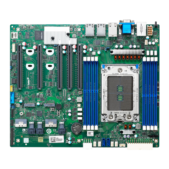
Page 12: Board Image
2.1 Board Image S8030 This picture is representative of the latest board revision available at the time of publishing. The board you receive may not look exactly like the above picture. http://www.tyan.com... -
Page 13: Block Diagram
2.2 Block Diagram S8030 Block Diagram http://www.tyan.com... -
Page 14: Mainboard Mechanical Drawing
2.3 Mainboard Mechanical Drawing http://www.tyan.com... -
Page 15: Board Parts, Jumpers And Connectors
2.4 Board Parts, Jumpers and Connectors This diagram is representative of the latest board revision available at the time of publishing. The board you receive may not look exactly like the above diagram. But for the DIMM number please refer to the above placement for memory installation. For the latest board revision, please visit our web site at http://www.tyan.com. - Page 16 Jumpers & Connectors Connectors 1 Micro SD Connector (J19) 16 System Fan Connector (J21) 2 System Fan Connector (J42) 17 SATA Connector (J22) 3 NVMe/SATA M.2 Slot (CN3) 18 SATA Connector (J14) 4 IPMB Header (J67) 19 System Fan Connector (J17) 5 Front USB3.1 Header (J32) 20 2x12pin PWR Connector (J60) 6 TPM Header (J40)
- Page 17 SYS_FAN1 (J17)/SYS_FAN2 (J21)/SYS_FAN3 (J18): System FAN Header Signal TACH Use this header to connect the cooling fan to your motherboard to keep the system stable and reliable. CPU_FAN (J34): CPU FAN Header Signal TACH Use this header to connect the cooling fan to your motherboard to keep the system stable and reliable.
- Page 18 J67: IPMB Pin Header Signal BMC_SMB_IPMB_5VS_DAT BMC_SMB_IPMB_5VS_CLK VDD_33_DUAL J40: LPC Debug Port and TPM Header Signal Signal VDD_33_RUN DBG_LFRAME_N DBG_LPC0 DBG_LPC1 DBG_PLTRST_N DBG_LPC2 DBG_LPC3 DBG_CLK DBG_SERIRQ DBG_PRES_N VDD_33_DUAL VDD_33_DUAL DBG_TPM_PP_EN J32: Front USB3.1 Header Signal Signal VDD_5_USB_REAR P0_USB_0_SS_0RX_ESD_L VDD_5_USB_REAR P0_USB_0_SS_0RX_ESD_H P0_USB_0_SS_1RX_ESD_L P0_USB_0_SS_1RX_ESD_H P0_USB_0_SS_0TX_ESD_L...
- Page 19 CN2 (NVME0_1) / CN4 (NVME2_3): Slim SAS 8x Connector Signal Name Pin Pin Signal Name NVME[0]/[2]_RX_P0 NVME[0]/[2]_TX_P0 NVME[0]/[2]_RX_N0 NVME[0]/[2]_TX_N0 NVME[0]/[2]_RX_P1 NVME[0]/[2]_TX_P1 NVME[0]/[2]_RX_N1 NVME[0]/[2]_TX_N1 CPU_HP_SMBUS_SCL[CN2/CN4] CPU_HP_SMBUS_SDA[CN2/CN4] A10 B10 NVME[0]/[2]_CLK_DP A11 B11 NVME[0]/[2]_PERST_L NVME[0]/[2]_CLK_DN A12 B12 A13 B13 NVME[0]/[2]_RX_P2 A14 B14 NVME[0]/[2]_TX_P2 NVME[0]/[2]_RX_N2 A15 B15 NVME[0]/[2]_TX_N2...
- Page 20 CN2 Link CN4 SMBus_SDA A27 B27 NVME[0,1]/[2,3]_SDA A28 B28 NVME[1]/[3]_CLK_DP A29 B29 NVME[1]/[3]_PERST_L NVME[1]/[3]_CLK_DN A30 B30 A31 B31 NVME[1]/[3]_RX_P2 A32 B32 NVME[1]/[3]_TX_P2 NVME[1]/[3]_RX_N2 A33 B33 NVME[1]/[3]_TX_N2 A34 B34 NVME[1]/[3]_RX_P3 A35 B35 NVME[1]/[3]_TX_P3 NVME[1]/[3]_RX_N3 A36 B36 NVME[1]/[3]_TX_N3 A37 B37 J25/J26/J27: Mini SAS HD Connector Signal Signal GND1...
- Page 21 J19: Micro SD Card Connector Signal DAT2 DAT3 VDD(3.3V) DAT0 DATA1 FAN_FP (J42): System Fan Connector (Reserved for Barebone) Signal Name Signal Name SYS_FAN_T1 SYS_FAN_T6 SYS_FAN_T2 SYS_FAN_T7 SYS_FAN_T3 SYS_FAN_T8 SYS_FAN_T9 SYS_FAN_T5 SYS_FAN_T10 BMC_PWM_BUF_FAN3 BMC_PWM_BUF_FAN2 SYS_FAN_T11 FAN_SDA SYS_FAN_T12 FAN_SCL VDD_33_DUAL BMC_PWM_BUF_FAN4 VDD_33_DUAL SYS_FAN_T13 SYS_FAN_T15...
- Page 22 CN1 / CN3: M.2 Slot Signal Signal VCC3 VCC3 RXN3 RXP3 LED1 TXN3 VCC3 TXP3 VCC3 VCC3 RXN2 VCC3 RXP2 TXN2 TXP2 RXN1 RXP1 TXN1 TXP1 DEVSLP I2C_M2_SCL RXN0/SATA-B+ I2C_M2_SDA RXP0/SATA-B- TXN0/SATA-A- TXP0/SATA-A+ CLK_N CLK_P SET PCIE/SATA VCC3 VCC3 VCC3 http://www.tyan.com...
- Page 23 Jumper Legend OPEN - Jumper OFF Without jumper cover CLOSED - Jumper ON With jumper cover J36: Clear CMOS Jumper You can reset the CMOS settings by using this jumper. This can be useful if you have forgotten your system/setup password, or need to clear the system BIOS setting.
- Page 24 J41: Reset Select Jumper Pin 1-2 Closed: FP Reset Button=System Reset (Default) Pin 2-3 Closed: FP Reset Button=BMC Reset J55/J56: BMC COM Select Jumper Pin 1-2 Closed: BMC COM Port1 (Default) Pin 2-3 Closed: BMC Console Port5 J43: Bypass BMC Jumper Pin 1-2 Closed: Bypass BMC Pin 2-3 Closed: FPGA waits for BMC ready (Default) J101: ID Button Switch...
-
Page 25: Led Definitions
2.5 LED Definitions Location State Description Note Interface shows on The blue System Identification LED is Interface shows off used to help identify a system for servicing ID LED when it is installed within a high density Blinking rack or cabinet that is populated with several other similar systems. -
Page 26: Installing The Processor And Heat Sink
Specifications on page 5. Check our website at http://www.tyan.com for latest processor support. NOTE: MITAC TYAN is not liable for damage as a result of operating an unsupported configuration. Processor Installation for AMD Socket SP3 Follow the steps below to install the processors and heat sinks. NOTE: Please save and replace the CPU protection cap when returning for service. - Page 27 Remove the external cap from the rail frame. Align and install the carrier frame with package into the slot on the rail frame. NOTE: During installation, observe the following: Make sure to push the carrier frame with package towards the end of the rail frame until it clicks into place.
- Page 28 Carefully close the rail frame with the installed package. Then push both edges of the rail frame firmly until it locks in place. Close the force frame. Then use a T20 Torx screwdriver to tighten the screws to secure the force frame in a sequential order (123). Align and install the CPU heatsink onto the top of the CPU socket.
- Page 29 Use a T20 Torx screwdriver to tighten the heatsink screws. Connect the heatsink power cable to the mainboard connector. NOTE: Always check with the manufacturer of the heat sink & processor to ensure that the thermal interface material is compatible with the processor and meets the manufacturer’s warranty requirements.
-
Page 30: Tips On Installing Motherboard In Chassis
Some chassis include plastic studs instead of metal. Although the plastic studs are usable, MITAC recommends using metal studs with screws that will fasten the motherboard more securely in place. Below is a chart detailing what the most common motherboard studs look like and how they should be installed. - Page 31 http://www.tyan.com...
-
Page 32: Installing The Memory
2.8 Installing the Memory Before installing memory, ensure that the memory you have is compatible with the http://www.tyan.com motherboard and processor. Check the TYAN Web site at for details of the type of memory recommended for your motherboard. This platform supports (4)+(4) DDR4 ECC RDIMM/RDIMM 3DS/LRDIMM/ LRDIMM 3DS 3200 ... - Page 33 NOTE: 1. √ indicates a populated DIMM slot. 2. Use paired memory installation for max performance. 3. Populate the same DIMM type in each channel, specifically - Use the same DIMM size - Use the same # of ranks per DIMM Memory Population Table Quantity of Memory Module Populated Single CPU Populated...
- Page 34 Memory Installation Procedure Follow these instructions to install memory modules into the S8030. Unlock the clips as shown in the illustration. Insert the memory module firmly into the socket by gently pressing down until it sits flush with the socket. Lock the clips to secure the memory module into place.
-
Page 35: Attaching Drive Cables
2.9 Attaching Drive Cables Attaching Serial ATA Cables S8030 is equipped with two (2) Serial ATA (SATA) channel. Connections for the drives are very simple. There is no need to set Master/Slave jumpers on SATA drives. If you are in need of SATA/SAS cables or power adapters please contact your place of purchase. -
Page 36: Installing Add-In Cards
2.10 Installing Add-In Cards Before installing add-in cards, it’s helpful to know if they are fully compatible with your motherboard. For this reason, we’ve provided the diagrams below, showing the slots that may appear on your motherboard. PCI-E Gen4 x16 slot Simply find the appropriate slot for your add-in card and insert the card firmly. -
Page 37: Connecting External Devices
2.11 Connecting External Devices Connecting external devices to the motherboard is an easy task. The motherboard supports a number of different interfaces through connecting peripherals. See the following diagrams for the details. NOTE: Peripheral devices can be plugged straight into any of these ports but software may be required to complete the installation. -
Page 38: Installing The Power Supply
2.12 Installing the Power Supply There are three (3) power connectors on your S8030 motherboard. The S8030 supports EPS 12V power supply. J60: ATX 24-pin Main Power Connector Signal Signal VDD_33_RUN VDD_33_RUN VDD_33_RUN N12V VDD_5_RUN PS_ON_L VDD_5_RUN PWRGD_PS VDD_5_STBY_PSU VDD_5_RUN VDD_12_RUN VDD_5_RUN VDD_12_RUN... -
Page 39: Finishing Up
2.13 Finishing Up Congratulations on making it this far! You have finished setting up the hardware aspect of your computer. Before closing up your chassis, make sure that all cables and wires are connected properly, especially IDE cables and most importantly, jumpers. - Page 40 NOTE http://www.tyan.com...
-
Page 41: Chapter 3: Bios Setup
Chapter 3: BIOS Setup 3.1 About the BIOS The BIOS is the basic input/output system, the firmware on the motherboard that enables your hardware to interface with your software. The BIOS determines what a computer can do without accessing programs from a disk. The BIOS contains all the code required to control the keyboard, display screen, disk drives, serial communications, and a number of miscellaneous functions. - Page 42 Chipset section unless you are absolutely sure of what you are doing. The Chipset defaults have been carefully chosen either by MITAC or your system manufacturer for best performance and reliability. Even a seemingly small change to the Chipset setup options may cause the system to become unstable or unusable.
-
Page 43: Main Menu
3.2 Main Menu In this section, you can alter general features such as the date and time. Note that the options listed below are for options that can directly be changed within the Main Setup screen. System Language Choose the system default language. English / Simplified Chinese / Japanese System Date Set the Date. -
Page 44: Advanced Menu
3.3 Advanced Menu This section facilitates configuring advanced BIOS options for your system. Tls Auth Configuration Press <Enter> to select Tls Auth Configuration. iSCSI Configuration Configure the iSCSI parameters. VLAN Configuration (MAC: 5AB600CEFD03) VLAN Configuration (MAC: 5AB600CEFD03) MAC: 5AB600CEFD03 --- IPV4 Network Configuration Configure IPV4 network parameters. - Page 45 CPU Configuration CPU Configuration Parameters. ACPI Settings System ACPI Parameters. S5 RTC Wake Settings Enable system to wake from S5 using RTC alarm. Serial Port Console Redirection Serial Port Console Redirection. PCI Subsystem Settings PCI, PCI-X and PCI Express Settings. CSM Configuration CSM configuration: Enable/Disable, Option ROM execution settings, etc.
- Page 46 3.3.1 T1s Auth Configuration Server CA Configuration Press <Enter> to configure Server CA. Client Cert Configuration Press <Enter> to configure Client Cert. http://www.tyan.com...
- Page 47 3.3.1.1 Server CA Configuration Enroll Cert Press <Enter> to enroll cert. Delete Cert Press <Enter> to delete cert. http://www.tyan.com...
- Page 48 3.3.1.1.1 Enroll Cert Enroll Cert Using File Enroll Cert Using File. Cert GUID Input digit character in 11111111-2222-3333-4444-1234567890ab format. Commit Changes and Exit Commit Changes and Exit. Discard Changes and Exit Discard Changes and Exit. http://www.tyan.com...
- Page 49 3.3.1.2 Delete Cert FE9C6606-8849-44A3-8868-DEA3A0E0324D GUID for CERT. Disabled / Enabled http://www.tyan.com...
- Page 50 3.3.2 iSCSI Configuration Please follow the instructions to initiate the iSCSI function. Step 1. Select Advanced CSM Configuration Network [UEFI]. Step 2. Select Advanced Network Stack Configuration Network Stack [Enabled] Step 3. Save changes and reboot. iSCSI Initiator Name The worldwide unique name of iSCSI Initiator.
- Page 51 3.3.2.1 Add an Attempt Read only. NOTE: Only LAN1 supports iSCSI function. http://www.tyan.com...
- Page 52 3.3.2.1.1 MAC 5A:B6:00:CE:FD:03 iSCSI Attempt Name The human name defined for this attempt. Maximum length is up to 12 characters. Attempt 1 / Attempt # iSCSI Mode Disabled, Enabled, Enabled for MPIO. Disabled / Enabled / Enabled for MPIO Internet Protocol Initiator IP address is system assigned in IP6 mode.
- Page 53 Connection Establishing Timeout The timeout value in milliseconds. The minimum value is 100 milliseconds and the maximum is 20 seconds. Configure ISID OUI-format ISID in 6 bytes, default value is derived from MAC address. Only last 3 bytes are configurable. Example: update 0ABBCCDDEEFF to OABBCCF07901 by input F07901.
- Page 54 3.3.2.2 Delete Attempts Attempt 1 MAC: 5A:B6:00:CE:FD:03, PFA: Bus 6/ Dev 0 / Func 3, iSCSI mode: Disabled, IP version: IPv4. Disabled / Enabled Commit Changes and Exit Commit Changes and Exit. Discard Changes and Exit Discard Changes and Exit. http://www.tyan.com...
- Page 55 3.3.2.3 Change Attempt Order Change Attempt Order Change the order of Attempts using +/- keys. Use arrow keys to select the attempt then press +/- to move the attempt up/down in the attempt order list. Attempt 1 / Attempt # Commit Changes and Exit Commit Changes and Exit.
- Page 56 3.3.3 VLAN Configuration (MAC:5AB600CEFD03) Enter Configuration Menu Press ENTER to enter configuration menu for VLAN configuration. http://www.tyan.com...
- Page 57 3.3.3.1 Enter Configuration Menu VLAN ID VLAN ID of new VLAN or existing VLAN, valid value is 0~4094. Priority 802.1Q Priority, valid value is 0~7. Add VLAN Create a new VLAN or update existing VLAN. Remove VLAN Remove selected VLANs. http://www.tyan.com...
- Page 58 3.3.4 MAC:5AB600CEFD03-IPv4 Network Configuration Configured Indicate whether network address configured successfully or not. Disabled / Enabled Save Changes and Exit Save Changes and Exit. http://www.tyan.com...
- Page 59 3.3.5 MAC:5AB600CEFD03-IPv6 Network Configuration Enter Configuration Menu Press ENTER to enter configuration menu for IPv6 configuration. http://www.tyan.com...
- Page 60 3.3.5.1 Enter Configuration Menu Interface ID The 64 bit alternative interface ID for the device. The string is colon separated, e.g. ff:dd:88:66:cc:1:2:3 58:86:0:FF:FE:CE:FD:3 DAD Transmit Count The number of consecutive Neighbor Solicitation messages sent while performing Duplicate Address Detection on a tentative address. A value of zero indicates that Duplicate Address Detection is not performed.
- Page 61 3.3.5.1.1 Advanced Configuration New IPv6 address Manual IP address can only be configured under manual policy. Separate the IP address with blank space to configure more than one address. e.g. 2002::1/64 2002::2/64 New Gateway addresses Gateway IP address can only be configured under manual policy. e.g. 2002::3. Separate the IP address with blank space to configure more than one address.
- Page 62 3.3.6 Network Stack Configuration NOTE: The BIOS will automatically read the onboard LAN controller. Network Stack Enable/Disable UEFI Network Stack. Disabled / Enabled Ipv4 PXE Support Enable Ipv4 PXE Boot Support. If disabled IPV$ PXE boot option will not be created. Disabled / Enabled Ipv4 HTTP Support Enable Ipv4 HTTP Boot Support.
- Page 63 Ipv6 HTTP Support Enable Ipv6 HTTP Boot Support. If disabled IPV6 HTTP boot option will not be created. Disabled / Enabled IPSEC Certificate Support to Enable/Disable IPSEC certificate for Ikev. Disabled / Enabled PXE boot wait time Wait time to press ESC key to abort the PXE boot. Media detect count Number of times presence of media will be checked.
- Page 64 3.3.7 CPU Configuration SVM Mode Enable/disable CPU Virtualization. Disabled / Enabled SMEE Control secure memory encryption enable. Disabled / Enabled CPU 0 Information View Information related to CPU 0. http://www.tyan.com...
- Page 65 3.3.7.1 CPU 0 Information Read only. http://www.tyan.com...
- Page 66 3.3.8 ACPI Settings Enable ACPI Auto Configuration Enable or disable BIOS ACPI Auto Configuration. Disabled / Enabled http://www.tyan.com...
- Page 67 3.3.9 S5 RTC Wake Settings Wake system from S5 Enable or disable System wake on alarm event. Select Fixed Time, system will wake on the hr:min:sec specified. Select Dynamic Time, system will wake on the current time + increase minute(s). Disabled / Fixed Time / Dynamic Time When Wake system from S5 is set to [Fixed Time] Wake up hour...
- Page 68 3.3.10 Serial Port Console Redirection COM1 / Serial Port for Out-Of-Band Management/Windows Emergency Services (EMS) Console Redirection Console redirection enable or disable. Disabled / Enabled Legacy Console Redirection Settings Legacy Console redirection settings. Console Redirection Settings The settings specify how the host computer (which the user is using) will exchange data.
- Page 69 3.3.10.1 COM1 Console Redirection Settings Terminal Type Emulation: ANSI: Extended ASCII char set. VT100: ASCII char set. VT100+: Extends VT100 to support color, function keys, etc. VT-UTF8: Uses UTF8 encoding to map Unicode chars onto 1 or more bytes. VT100+ / VT100 / VT-UTF8 / ANSI Bits per Second Select serial port transmission speed.
- Page 70 Stop Bits Stop bits indicate the end of a serial data packet. (A start bit indicates the beginning). The standard setting is 1 stop bit. Communication with slow devices may require more than 1 stop bit. 1 / 2 Flow Control Flow Control can prevent data loss from buffer overflow.
- Page 71 3.3.10.2 Legacy Console Redirection Settings Legacy Serial Redirection Port Select a COM port to display redirection of Legacy OS and Legacy OPROM Messages. COM1 Resolution On Legacy OS, the Number of Rows and Columns supported redirection. 80x24 / 80x25 Redirect After POST When BootLoader is selected, then Legacy Console Redirection is disabled before booting to legacy OS, When Always Enable is selected, then Legacy Console Redirection is enabled for legacy OS.
- Page 72 3.3.10.3 Serial Port for Out-Of-Band Management/Windows Emergency Services (EMS) Console Redirection Settings Out-of-Band Mgmt Port Microsoft Windows Emergency Management Services (EMS) allows for remote management of a Windows Server OS through a serial port. COM1 Terminal Type VT-UTF8 is the preferred terminal type for out-of-band management. The next best choice is VT100+ and then VT100.
- Page 73 Flow Control Flow Control can prevent data loss from buffer overflow. When sending data, if the receiving buffers are full, a ‘stop’ signal can be sent to stop the data flow. Once the buffers are empty, a ‘start’ signal can be sent to restart the flow. Hardware flow control uses two wires to send start/stop signal.
- Page 74 3.3.11 PCI Subsystem Settings Above 4G Decoding Enables or Disables 64bit capable Devices to be Decoded in Above 4G Address Space (Only if System Supports 64 bit PCI Decoding). Enabled / Disabled SR-IOV Support If system has SR-IOV capable PCIe Devices, this option Enables or Disables Single Root IO Virtualization Support.
- Page 75 3.3.11.1 PCI Express Settings Maximum Payload Set Maximum Payload of PCI Express Device or allow System BIOS to select the value. Auto / 128 Bytes / 256 Bytes / 512 Bytes / 1024 Bytes / 2048 Bytes / 4096 Bytes http://www.tyan.com...
- Page 76 3.3.12 CSM Configuration CSM support Enable/Disable CSM Support Enabled / Disabled Option ROM Messages Set display mode for Option ROM Force BIOS / Keep Current Network Controls the execution of UEFI and Legacy PXE OpROM UEFI / Legacy Storage Controls the execution of UEFI and Legacy Storage OpROM UEFI / Legacy Video Controls the execution of UEFI and Legacy Video OpROM...
- Page 77 Other PCI devices Determines OpRom execution policy for devices other than network, storage, or video UEFI / Legacy http://www.tyan.com...
- Page 78 3.3.13 USB Configuration Legacy USB Support Enables USB legacy support. AUTO option disables legacy support if no USB devices are connected. DISABLE option will keep USB devices available only for EFI applications. Enabled / Disabled / Auto XHCI Hand-off This is a workaround for OSes without XHCI hand-off support. The XHCI ownership change should be claimed by XHCI driver.
- Page 79 USB transfer time-out The time-out value for Control, Bulk and Interrupt transfers. 1 sec / 5 sec / 10 sec / 20 sec Device reset time-out USB mass storage device Start Unit command time-out. 10 sec / 20 sec / 30 sec / 40 sec Device power-up delay Maximum time the device will take before it properly reports itself to the Host Controller.
- Page 80 3.3.14 Onboard Device Configuration Onboard VGA Enable or disable onboard VGA. Enabled / Disabled Active Video Select between onboard or external VGA support. Onboard / Offboard LAN1 LAN Enable/Disable control function. Enabled / Disabled LAN2 LAN Enable/Disable control function. Enabled / Disabled LAN3 (for S8030GM4NE-2T SKU only) LAN Enable/Disable control function.
- Page 81 LAN4 (for S8030GM4NE-2T SKU only) LAN Enable/Disable control function. Enabled / Disabled NMI Button Enable or Disable NMI button. Enabled / Disabled Clock Spread Spectrum Enable/Disable CG1_PLL Spread Spectrum. Enabled / Disabled http://www.tyan.com...
- Page 82 3.3.15 NVMe Configuration Read only. http://www.tyan.com...
- Page 83 3.3.16 SATA Configuration Read only. http://www.tyan.com...
- Page 84 3.3.17 Trusted Computing Security Device Support Enables or Disables BIOS support for security device. O.S. will not show Security Device. TCG EFI protocol and INT1A interface will not be available. Enabled / Disabled http://www.tyan.com...
- Page 85 3.3.18 PCIE Slot Configuration PCIe Slot Bifurcation Configuration PCIE#1~PCIE#5 Selects PCIe port Bifurcation for PCIE#1~PCIE#5 slot. x16 / x8x8 / x4x4x4x4 PCIe Slot Link Speed Configuration PCIE#1~PCIE#5 Maximum Link Speed for PCIE#1~PCIE#5 slot. Auto / Gen1 (2.5GT/s) / Gen2 (5GT/s) / Gen3 (8GT/s) / Gen4 (16GT/s) http://www.tyan.com...
- Page 86 3.3.19 Option ROM Dispatch Policy LAN1 (for S8030GM4NE-2T SKU only) Enable or Disable LAN1 Option ROM. Enabled / Disabled LAN2 (for S8030GM4NE-2T SKU only) Enable or Disable LAN2 Option ROM. Enabled / Disabled LAN3 Enable or Disable LAN3 Option ROM. Enabled / Disabled LAN4 Enable or Disable LAN4 Option ROM.
- Page 87 3.3.20 AST2500 Super IO Configuration Super IO Chip Read only. Serial Port 1 Configuration Set Parameters of Serial Port 1 (COMA). http://www.tyan.com...
- Page 88 3.3.20.1 Serial Port 1 Configuration Serial Port Enable or disable Serial Port (COM). Enabled / Disabled Device Settings Read only. Change Settings Select an optimal setting for Super IO Device. Auto / IO=3F8h; IRQ=4; / IO=3F8h, IRQ=3, 4, 5, 6, 7, 9, 10, 11, 12; / IO=2F8h;...
- Page 89 3.3.21 Hardware Health Configuration Fan Speed Control Fan Speed Control. Manual / Full Speed NOTE: Change the “Fan Speed Control” BIOS setting from [Manual] to [Full Speed] when installing the Nvidia GeForce / Quardro GPU and any VGA card. PWM Minimal Duty Cycle PWM Minimal Duty Cycle (%).
- Page 90 3.3.21.1 Sensor Data Register Monitoring NOTE: SDR can not be modified. Read only. http://www.tyan.com...
- Page 91 3.3.22 Redfish Host Interface Settings BMC Redfish Version Redfish version supported by BMC. 1.5.b BIOS Redfish Version Redfish version supported by BIOS. 1.5.b IP Address Read only. IP Mask Address Read only. IP Port Read only. http://www.tyan.com...
-
Page 92: Chipset Menu
3.4 Chipset Menu PCIe Compliance Mode PCIe Link Compliance Mode. Disabled / Enabled North Bridge North Bridge Parameters http://www.tyan.com... - Page 93 3.4.1 North Bridge Configuration Socket 0 Configuration View Information related to Socket 0. http://www.tyan.com...
- Page 94 3.4.1.1 Socket 0 Information Read only. http://www.tyan.com...
-
Page 95: Amd Cbs
3.5 AMD CBS CPU Common Options CPU Common Options. DF Common Options DF Common Options. UMC Common Options UMC Common Options. NBIO Common Options NBIO Common Options. FCH Common Options FCH Common Options. http://www.tyan.com... - Page 96 3.5.1 CPU Common Options CCD/Core/Thread Enablement CCD/Core/Thread Enablement. Prefetcher Settings Prefetcher Settings. Platform First Error Handling Enable/disable PFEH, cloak individual banks, and mask deferred error interrupts from each bank. Enabled / Disabled / Auto Core Performance Boost Disable CPB. Disabled / Auto Global C-state Control Controls IO based C-state generation and DF C-states.
- Page 97 SEV-ES ASID Space Limit Control SEV-ES ASID Space Limit Control. Auto / Manual NOTE: SEV-ES ASID Space Limit is available when SEV-ES ASID Space Limit Control is set to [Manual]. SEV-ES ASID Space Limit ASIDs from SEV-ES ASID Space Limit to (SEV ASID Count +1) can only be used with SEV VMs.
- Page 98 3.5.1.1 Core/Thread Enablement CCD control Sets the number of CCDs to be used. Once this option has been used to remove any CCDs, a POWER CYCLE is required in order for future selections to take effect. Auto / 2 CCDs / 3 CCDs / 4 CCDs / 6 CCDs Core control Sets the number of cores to be used.
- Page 99 3.5.1.2 Prefetcher Settings L1 Stream HW Prefetcher Option to Enable / Disable L1 Stream HW Prefetcher. Enabled / Disabled / Auto L2 Stream HW Prefetcher Option to Enable / Disable L2 Stream HW Prefetcher. Enabled / Disabled / Auto http://www.tyan.com...
- Page 100 3.5.2 DF Common Options Scrubber Scrubber. Memory Addressing Memory Addressing. ACPI ACPI. http://www.tyan.com...
- Page 101 3.5.2.1 Scrubber DRAM scrub time Provide a value that is the number of hours to scrub memory. Disabled / 1 hour / 4 hours / 8 hours / 16 hours / 24 hours / 48 hours / Auto Poison scrubber control Poison scrubber control.
- Page 102 3.5.2.2 Memory Addressing NUMA nodes per socket Specifies the number of desired NUMA nodes per socket. Zero will attempt to interleave the two sockets together. NPS0 / NPS1 / NPS2 / NPS4 / Auto Memory interleaving Allows for disabling memory interleaving. Note that NUMA nodes per socket will be honored regardless of this setting.
- Page 103 3.5.2.3 ACPI ACPI SRAT L3 Cache As NUMA Domain Enabled: Each CCX in the system will be declared as a separate NUMA domain. Disabled: Memory Addressing \ NUMA nodes per socket will be declared. Disabled / Enabled / Auto http://www.tyan.com...
- Page 104 3.5.3 UMC Common Options DDR4 Common Options DDR4 Common Options. DRAM Memory Mapping DRAM Memory Mapping. NVDIMM NVDIMM. http://www.tyan.com...
- Page 105 3.5.3.1 DDR4 Common Options DRAM Timing Configuration DRAM Timing Configuration. Common RAS Common RAS. Security Security. http://www.tyan.com...
- Page 106 3.5.3.1.1 DRAM Timing Configuration Overclock Memory Overclock Settings. Enabled / Auto Memory Clock Speed Specifies the memory clock frequency. 2666MT/s / 2933MT/s / 3200MT/s / Auto http://www.tyan.com...
- Page 107 3.5.3.1.2 Common RAS Data Poisoning Enable/disable data poisoning: Enabled / Disabled / Auto ECC Configuration ECC Configuration. http://www.tyan.com...
- Page 108 3.5.3.1.2.1 ECC Configuration DRAM ECC Symbol Size DRAM ECC Symbol Size (x4/x8/x16) . x4 / x8 / x16 / Auto DRAM ECC Enable Use this option to enable/disable DRAM ECC. Auto will set ECC to enable. Enabled / Disabled / Auto http://www.tyan.com...
- Page 109 3.5.3.1.3 Security TSME Transparent SME. Enabled / Disabled / Auto Data Scramble Data scrambling. Enabled / Disabled / Auto http://www.tyan.com...
- Page 110 3.5.3.2 DRAM Memory Mapping Chipselect Interleaving Interleave memory blocks across the DRAM chip selects for node 0. Disabled / Auto BankGroupSwap Bank Group Swap settings. Enabled / Disabled / Auto http://www.tyan.com...
- Page 111 3.5.3.3 NVDIMM NVDIMM-N Feature Disable NVDIMM-N feature for memory margin tool. Disabled / Enabled http://www.tyan.com...
- Page 112 3.5.4 NBIO Common Options IOMMU Enable/Disable IOMMU. Enabled / Disabled / Auto ACS Enable AER must be enabled for ACS enable to work. Enabled / Disabled / Auto PCIe ARI Support Enables Alternative Routing-ID Interpretation. Enabled / Disabled / Auto SMU Common Options SMU Common Options.
- Page 113 The following item is available when Preferred IO is set to [Manual]. Preferred IO Bus Preferred IO Bus Number 0x0-0xFF: Bus Number http://www.tyan.com...
- Page 114 3.5.4.1 SMU Common Options Determinism Control Auto = Use the fused Determinism Manual = User can set customized Determinism Manual / Auto NOTE: Determinism Slider is available when Determinism Control is set to [Manual]. Determinism Slider Auto = Use default performance determinism settings Power Performance Auto / Power / Performance...
- Page 115 cTDP cTDP [W] 0 = Invalid value. Package Power Limit Control Auto = Use the fused PPT Manual = User can set customized PPT ***PPT will be used as the ACIS power limit*** Manual / Auto NOTE: Package Power Limit is available when Package Power Limit Control is set to [Manual].
- Page 116 3.5.5 FCH Common Options AC Power Loss Options AC Power Loss Options. http://www.tyan.com...
- Page 117 3.5.4.1 AC Power Loss Options Restore AC Power Loss Select Restore AC Power Loss Method. Power Off / Power On / Last State http://www.tyan.com...
-
Page 118: Server Management
3.6 Server Management FRB-2 Timer Enable or Disable FRB-2 timer (POST timer). Enabled / Disabled FRB-2 Timer timeout Enter value Between 3 to 6 min for FRB-2 Timer Expiration value. Not available if FRB-2 Timer is disabled. 3 minutes / 4 minutes / 5 minutes / 6 minutes FRB-2 Timer Policy Configure how the system should respond if the FRB-2 Timer expires. - Page 119 OS Wtd Timer timeout Configure the length of the OS Boot Watchdog Timer. Not available if OS Boot Watchdog timer is disabled. 5 minutes / 10 minutes / 15 minutes / 20 minutes OS Wtd Timer Policy Configure how the system should respond if the OS Boot Watchdog Timer expires. Not available if OS Boot Watchdog timer is disabled.
- Page 120 3.6.1 System Event Log SEL Components Change this to enable or disable all features of System Event Logging during boot. Disabled / Enabled NOTE: When SEL Components is set to [Disabled], the following items are read only. Erase SEL Choose options for erasing SEL. No / Yes, on next reset / Yes, on every reset When SEL is Full Choose options for reactions to a full SEL.
- Page 121 3.6.2 BMC Network Configuration Configuration Address Source Select the configure LAN channel parameters statically or dynamically (by BIOS or BMC). Unspecified option will not modify any BMC network parameters during BIOS phase. Unspecified / Static / DynamicBmcDhcp / DynamicBmcNonDhcp Management Port 2 (for S8030GM4NE-2T SKU only) Enable/Disable BMC Share NIC.
- Page 122 3.6.3 BMC User Settings Add User Press <Enter> to Add a user. Delete User Press <Enter> to Delete a user. Change User Settings Press <Enter> to change User Settings. http://www.tyan.com...
- Page 123 3.6.3.1 Add User User Name Enter BMC User Name. Change User Password Enter New Password to change. Password at least 8 characters. User Access Enable/Disable the BMC User’s Access. Enabled / Disabled Channel No Enter BMC Channel Number. 1 – Dedicated LAN 8 –...
- Page 124 3.6.3.2 Delete User User Name Enter BMC User Name. Change User Password Enter New Password to change. Password at least 8 characters. http://www.tyan.com...
- Page 125 3.6.3.3 Change User Settings User Name Enter BMC User Name. Change User Password Enter New Password to change. Password at least 8 characters. User Access Enable/Disable the BMC User’s Access. Enabled / Disabled Channel No Enter BMC Channel Number. 1 – Dedicated LAN 8 –...
-
Page 126: Security
3.7 Security Administrator Password Set administrator password in the Create New Password window. After you key in the password, the Confirm New Password window will pop out to ask for confirmation. User Password Set user password in the Create New Password window. After you key in the password, the Confirm New Password window will pop out to ask for confirmation. - Page 127 3.7.1 Secure Boot Secure Boot Secure Boot feature is Active if Secure Boot is Enabled. Platform Key (PK) is enrolled and the System is in User mode. The mode change requires platform reset. Enabled / Disabled Secure Boot Mode Secure Boot mode selector: Standard/Custom. In Custom mode Secure Boot Variables can be configured without authentication.
- Page 128 3.7.1.1 Key Management Factory Key Provision Install factory default Secure Boot keys after the platform reset and while the System is in Setup mode. Enabled / Disabled Restore Factory Keys Force System to User Mode. Install factory default Secure Boot key databases. Press ‘Yes’...
- Page 129 Enroll Efi Image Allow the image to run in Secure Boot mode. Enroll SHA256 Hash certificate of a PE image into Authorized Signature Database (db). Remove ‘UEFI CA’ from DB Device Guard ready system must not list ‘Microsoft UEFI CA’ Certificate in Authorized Signature database (db).
- Page 130 Details / Export / Update / Append / Delete Forbidden Signatures Enroll Factory Defaults or load certificates from a file: 1. Public Key Certificate in: a) EFI_SIGNATURE_LIST b) EFI_CERT_X509 (DER) c) EFI_CERT_RSA2048 (bin) d) EFI_CERT_SHAXXX 2. Authenticated UEFI Variable 3. EFI PE/C0FF Image (SHA256) Key source: Factory, External, Mixed Details / Export / Update / Append / Delete Authorized TimeStamps...
-
Page 131: Boot
3.8 Boot Setup Prompt Timeout Number of seconds to wait for setup activation key. 65535 (0xFFFF) means indefinite waiting. Bootup NumLock State Select the keyboard NumLock state. Off / On Quiet Boot Enable or disable Quiet Boot option. Enabled / Disabled Endless Boot Enable or disable Endless Boot. - Page 132 Wait for ‘ESC’ If Error Wait for ‘ESC’ key to be pressed if error occurs. Enabled / Disabled Boot Option Priorities Boot Option #1 Select the first/second boot device. Device Name / Disabled Delete Boot Option Remove an EFI boot option from the boot order. http://www.tyan.com...
- Page 133 3.8.1 Delete Boot Option Delete Boot Option Remove an EFI boot option from the boot order. Select one to delete / UEFI: Built-in EFI Shell http://www.tyan.com...
-
Page 134: Save & Exit
3.9 Save & Exit Save Changes and Exit Exit system setup after saving the changes. Discard Changes and Exit Exit system setup without saving any changes. Save Changes and Reset Reset the system after saving the changes. Discard Changes and Reset Reset system setup without saving any changes. - Page 135 Restore Defaults Restore/Load Default values for all the setup options. Save as User Defaults Save the changes done so far as User Defaults. Restore User Defaults Restore the User Defaults to all the setup options. Boot Override Read only. http://www.tyan.com...
- Page 136 NOTE http://www.tyan.com...
-
Page 137: Chapter 4: Diagnostics
Chapter 4: Diagnostics NOTE: if you experience problems with setting up your system, always check the following things in the following order: Memory, Video, CPU By checking these items, you will most likely find out what the problem might have been when setting up your system. -
Page 138: Amibios Post Code (Aptio)
4.2 AMIBIOS Post Code (Aptio) The POST code checkpoints are the largest set of checkpoints during the BIOS pre- boot process. The following table describes the type of checkpoints that may occur during the POST portion of the BIOS: Checkpoint Ranges Status Code Range Description 0x01 –... - Page 139 SEC Error Codes 0x0C – 0x0D Reserved for future AMI SEC error codes 0x0E Microcode not found 0x0F Microcode not found SEC Beep Codes None PEI Phase Status Code Description Progress Codes 0x10 PEI Core is started 0x11 Pre-memory CPU initialization is started 0x12 Pre-memory CPU initialization (CPU module specific) 0x13...
- Page 140 Status Code Description 0x38 Post-Memory North Bridge initialization (North Bridge module specific) 0x39 Post-Memory North Bridge initialization (North Bridge module specific) 0x3A Post-Memory North Bridge initialization (North Bridge module specific) 0x3B Post-Memory South Bridge initialization is started 0x3C Post-Memory South Bridge initialization (South Bridge module specific) 0x3D Post-Memory South Bridge initialization (South Bridge module specific) 0x3E...
- Page 141 Recovery Progress Codes 0xF0 Recovery condition triggered by firmware (Auto recovery) 0xF1 Recovery condition triggered by user (Forced recovery) 0xF2 Recovery process started 0xF3 Recovery firmware image is found 0xF4 Recovery firmware image is loaded 0xF5 – 0xF7 Reserved for future AMI progress codes Recovery Error Codes 0xF8 Recovery PPI is not available...
- Page 142 Status Code Description 0x76 South Bridge DXE initialization (South Bridge module specific) 0x77 South Bridge DXE initialization (South Bridge module specific) 0x78 ACPI module initialization 0x79 CSM initialization 0x7A – 0x7F Reserved for future AMI DXE codes 0x80 – 0x8F OEM DXE initialization codes 0x90 Boot Device Selection (BDS) phase is started...
- Page 143 Status Code Description 0xAF Exit Boot Services event 0xB0 Runtime Set Virtual Address MAP Begin 0xB1 Runtime Set Virtual Address MAP End 0xB2 Legacy Option ROM initialization 0xB3 System Reset 0xB4 USB hot plug 0xB5 PCI bus hot plug 0xB6 Clean-up of NVRAM 0xB7 Configuration Reset (reset of NVRAM settings)
- Page 144 Status Code Description 0x40 System is waking up from the S4 sleep state 0xAC System has transitioned into ACPI mode. Interrupt controller is in PIC mode. 0xAA System has transitioned into ACPI mode. Interrupt controller is in APIC mode. http://www.tyan.com...
-
Page 145: Appendix I: Fan And Temp Sensors
Appendix I: Fan and Temp Sensors This section aims to help readers identify the locations of some specific FAN and Temp Sensors on the motherboard. A table of BIOS Temp sensor name explanation is also included for readers’ reference. Figure 1: Sensor Location NOTE: The red spot indicates the sensor. - Page 146 BIOS Temp Sensor Name Explanation: http://www.tyan.com...
- Page 147 BIOS Temp Sensor Name Explanation CPU_Tctl_Value CPU Tempterature SYS_Air_Inlet Sensor connected to the Front Panel MB_Air_Inet Temperature of the M/B Air Inlet Area SYS_Air_Outlet Temperature of the System Air Outlet Area X550_Temp Temperature of Intel LAN X550 chipset CPU_CORE_MOSFET Max Temperature of CPU_CORE_MOSFET CPU_SOC_MOSFET Max Temperature of CPU_SOC_ MOSFET DIMM_MOSFET_1...
- Page 148 SYS_FAN_6 Fan Speed of SYS_FAN_6 SYS_FAN_7 Fan Speed of SYS_FAN_7 SYS_FAN_8 Fan Speed of SYS_FAN_8 SYS_FAN_9 Fan Speed of SYS_FAN_9 SYS_FAN_10 Fan Speed of SYS_FAN_10 SYS_FAN_11 Fan Speed of SYS_FAN_11 SYS_FAN_12 Fan Speed of SYS_FAN_12 PSU0_STATUS Current status of PSU0 PSU0_Temp Temperature of PSU0 PSU0_FAN...
-
Page 149: Appendix Ii: M.2 Latch Installation
Appendix II: M.2 Latch Installation This section provides a step-by-step demonstration on how to install a M.2 latch. 1. Take out the M.2 latch packs from the Accessory Box. 2. Insert the M.2 latch into the hole and then turn 90 degrees to the left as shown below. - Page 150 NOTE: The arrow sign on the blue knob is now turned left. 3. Push the blue knob slightly to the left as the arrow shows to lock the M.2 card in place. http://www.tyan.com...
- Page 151 4. The installation of the M.2 latch is now complete. http://www.tyan.com...
- Page 152 NOTE http://www.tyan.com...
-
Page 153: Glossary
Glossary ACPI (Advanced Configuration and Power Interface): a power management specification that allows the operating system to control the amount of power distributed to the computer’s devices. Devices not in use can be turned off, reducing unnecessary power expenditure. AGP (Accelerated Graphics Port): a PCI-based interface which was designed specifically for demands of 3D graphics applications. - Page 154 Bus: a data pathway. The term is used especially to refer to the connection between the processor and system memory, and between the processor and PCI or ISA local buses. Bus mastering: allows peripheral devices and IDEs to access the system memory without going through the CPU (similar to DMA channels).
- Page 155 DRAM (Dynamic RAM): widely available, very affordable form of RAM which looses data if it is not recharged regularly (every few milliseconds). This refresh requirement makes DRAM three to ten times slower than non-recharged RAM such as SRAM. ECC (Error Correction Code or Error Checking and Correcting): allows data to be checked for errors during run-time.
- Page 156 I/O (Input/Output): the connection between your computer and another piece of hardware (mouse, keyboard, etc.) IRQ (Interrupt Request): an electronic request that runs from a hardware device to the CPU. The interrupt controller assigns priorities to incoming requests and delivers them to the CPU. It is important that there is only one device hooked up to each IRQ line;...
- Page 157 RAID (Redundant Array of Independent Disks): a way for the same data to be stored in different places on many hard drives. By using this method, the data is stored redundantly and multiple hard drives will appear as a single drive to the operating system.
- Page 158 Standby mode: in this mode, the video and hard drives shut down; all other devices continue to operate normally. UltraDMA-33/66/100: a fast version of the old DMA channel. UltraDMA is also called UltraATA. Without a proper UltraDMA controller, your system cannot take advantage of higher data transfer rates of the new UltraDMA/UltraATA hard drives.
-
Page 159: Technical Support
Technical Support If a problem arises with your system, you should first turn to your dealer for direct support. Your system has most likely been configured or designed by them and they should have the best idea of what hardware and software your system contains. - Page 160 NOTE: A receipt or copy of your invoice marked with the date of purchase is required before any warranty service can be rendered. You may obtain service by calling the manufacturer for a Return Merchandise Authorization (RMA) number. The RMA number Should be prominently displayed on the outside of the shipping carton and the package should be mailed prepaid.
Need help?
Do you have a question about the TYAN S8030 and is the answer not in the manual?
Questions and answers