Table of Contents
Advertisement
Quick Links
Copyright
Copyright © 2017 MITAC COMPUTING TECHNOLOGY CORPORATION. All rights
reserved. No part of this manual may be reproduced or translated without prior
written consent from MITAC COMPUTING TECHNOLOGY CORPORATION.
Trademark
All registered and unregistered trademarks and company names contained in this
manual are property of their respective owners including, but not limited to the
following.
®
TYAN
is a trademark of MITAC COMPUTING TECHNOLOGY CORPORATION.
®
Intel
is a trademark of Intel
AMI, AMI BIOS are trademarks of AMI Technologies.
®
Microsoft
, Windows
®
Nuvoton
is a trademark of Nuvoton Technology Corporation.
Notice
Information contained in this document is furnished by MITAC COMPUTING
TECHNOLOGY CORPORATION and has been reviewed for accuracy and reliability
prior to printing. MiTAC assumes no liability whatsoever, and disclaims any express
or implied warranty, relating to sale and/or use of TYAN
or warranties relating to fitness for a particular purpose or merchantability. MiTAC
retains the right to make changes to product descriptions and/or specifications at
any time, without notice. In no event will MiTAC be held liable for any direct or
indirect, incidental or consequential damage, loss of use, loss of data or other
malady resulting from errors or inaccuracies of information contained in this
document.
S5542
Version 1.0d
®
Corporation.
®
are trademarks of Microsoft Corporation.
http://www.tyan.com
®
products including liability
1
Advertisement
Table of Contents

Subscribe to Our Youtube Channel
Related Manuals for MiTAC Tyan S5542


Summary of Contents for MiTAC Tyan S5542
- Page 1 In no event will MiTAC be held liable for any direct or indirect, incidental or consequential damage, loss of use, loss of data or other malady resulting from errors or inaccuracies of information contained in this document.
- Page 2 http://www.tyan.com...
-
Page 3: Table Of Contents
Contents Before you begin… ..................4 Chapter 1: Instruction ................5 1.1 Congratulations ................. 5 1.2 Hardware Specifications ..............5 1.3 Software Specifications ..............18 Chapter 2: Board Installation ..............19 2.1 Board Image ..................20 ... -
Page 4: Before You Begin
Before you begin… Check the box contents! The retail motherboard package should contain the following: 1 x S5542 Motherboard 2 x SATA Cable 1 x Rear IO Shield 1 x S5542 Quick reference guide ® 1 x TYAN Driver’s and Utilities DVD IMPORTANT NOTE: Sales sample may not come with the accessory listed above. -
Page 5: Chapter 1: Instruction
® find all the information on all TYAN products as well as all the supporting documentation, FAQs, Drivers and BIOS upgrades. 1.2 Hardware Specifications TYAN S5542 (S5542G2NR-UHE) Socket Type / Q'ty LGA1151, (1) Supported CPU Intel Xeon processor E3-1200 Processor... - Page 6 Controller Intel I210-AT Connector (8) SATA Controller Intel C236 Storage SATA Speed 6.0 Gb/s RAID 0/1/10/5 (Intel RAID RST) Connector type D-Sub 15-pin Graphic Chipset Intel Processor Graphics(pGFX) (3) USB2.0 ports (2 via cable, 1 Type-A), (6) USB3.0 ports (4 at rear, 2 via cable) (2) ports (1 at rear, 1 via cable) (1) D-Sub 15-pin VGA port...
- Page 7 (1) S5542 Motherboard (1) Web User's manual, (1) Quick Package Contains Manual Installation Guide Installation CD (1) TYAN installation CD TYAN S5542 (S5542G2NR-UHE-M2) Socket Type / Q'ty LGA1151, (1) Supported CPU Intel Xeon processor E3-1200 Processor Series v6/v5 product family...
- Page 8 RAID 0/1/10/5 (Intel RAID RST) (1)M.2 connector M.2 connector (2242 only) Connector type D-Sub 15-pin Graphic Chipset Intel Processor Graphics(pGFX) (3) USB2.0 ports (2 via cable, 1 Type-A), (6) USB3.0 ports (4 at rear, 2 via cable) (2) ports (1 at rear, 1 via cable) (1) D-Sub 15-pin VGA port Input /Output RJ-45...
- Page 9 (1) S5542 Motherboard (1) Web User's manual, (1) Quick Package Contains Manual Installation Guide Installation CD (1) TYAN installation CD TYAN S5542 (S5542GM2NR) Socket Type / Q'ty LGA1151, (1) Supported CPU Intel Xeon processor E3-1200 Processor Series v6/v5 product family...
- Page 10 RST) Connector type D-Sub 15-pin Graphic Resolution Up to 1920x1200 Chipset Aspeed AST2400 (3) USB2.0 ports (2 via cable, 1 Type-A), (6) USB3.0 ports (4 at rear, 2 via cable) (2) ports (1 at rear, 1 via cable) (1) D-Sub 15-pin VGA port Input /Output (2) GbE ports, (1) Dedicated for RJ-45...
- Page 11 (1) S5542 Motherboard (1) Web User's manual, (1) Quick Package Contains Manual Installation Guide Installation CD (1) TYAN installation CD TYAN S5542 (S5542GM4NR) Socket Type / Q'ty LGA1151, (1) Supported CPU Intel Xeon processor E3-1200 Processor Series v6/v5 product family...
- Page 12 (dedicated for IPMI connection) Connector (6) SATA Controller Intel C232 Storage SATA Speed 6.0 Gb/s RAID 0/1/10/5 (Intel RAID RST) Connector type D-Sub 15-pin Graphic Resolution Up to 1920x1200 Chipset Aspeed AST2400 (3) USB2.0 ports (2 via cable, 1 Type-A), (6) USB3.0 ports (4 at rear, 2 via cable) (2) ports (1 at rear, 1 via cable) (1) D-Sub 15-pin VGA port...
- Page 13 (1) S5542 Motherboard (1) Web User's manual, (1) Quick Package Contains Manual Installation Guide Installation CD (1) TYAN installation CD TYAN S5542 (S5542WGM2NR) Socket Type / Q'ty LGA1151, (1) Supported CPU Intel Xeon processor E3-1200 Processor Series v6/v5 product family...
- Page 14 (1) PCI-E Gen.3 x16 slot (w/ x8 link), Expansion Slots PCI-E (2) PCI-E Gen.3 x1 slot (2) GbE ports + (1) dedicated for Port Q'ty IPMI Controller Intel I210-AT Broadcom BCM5221 PHY (dedicated for IPMI connection) (2) Mini-SAS HD Connector connectors (totally support 8 ports) Controller...
- Page 15 RoHS 6/6 Compliant Please refer to our Intel OS Operating System OS supported list supported list. Motherboard (1) S5542 Motherboard (1) Web User's manual, (1) Quick Package Contains Manual Installation Guide Installation CD (1) TYAN installation CD TYAN S5542 (S5542WGM4NR) http://www.tyan.com...
- Page 16 Socket Type / Q'ty LGA1151, (1) Supported CPU Intel Xeon processor E3-1200 Processor Series v6/v5 product family Thermal Design Max up to 80W Power (TDP) wattage Chipset Intel C232 Supported DIMM Qty (4) DIMM slots Unbuffered ECC UDIMM DDR4 DIMM Type / Speed 2133/2400 Memory Capacity...
- Page 17 (2) GbE ports, (1) Dedicated for RJ-45 IPMI (2) Mini-SAS HD (4-in-1) connectors SATA (6) SATA-III connectors PSMI (1) 1x5-pin header Others (1) Reset button/ (1) Power button Chipset Aspeed AST2400 Total (4) 4-pin headers Monitors temperature for CPU & Temperature memory &...
-
Page 18: Software Specifications
Humidity RoHS RoHS 6/6 Compliant Please refer to our Intel OS Operating System OS supported list supported list. Motherboard (1) S5542 Motherboard (1) Web User's manual, (1) Quick Package Contains Manual Installation Guide Installation CD (1) TYAN installation CD 6 SKU Comparison Table Expand. -
Page 19: Chapter 2: Board Installation
Unplug the power from your computer power supply and then touch a safely grounded object to release static charge (i.e. power supply case). For the safest conditions, MiTAC recommends wearing a static safety wrist strap. (2) Hold the motherboard by its edges and do not touch the bottom of the board, or flex the board in any way. -
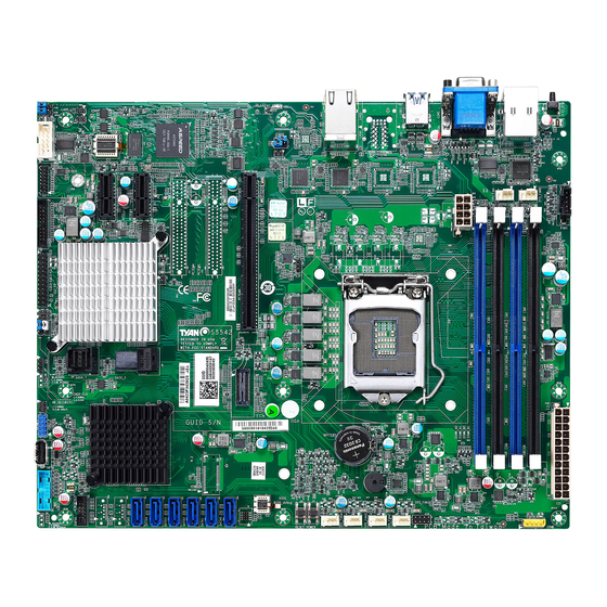
Page 20: Board Image
2.1 Board Image S5542 This picture is representative of the latest board revision available at the time of publishing. The board you receive may not look exactly like the above picture. http://www.tyan.com... -
Page 21: Block Diagram
2.2 Block Diagram S5542 Block Diagram http://www.tyan.com... -
Page 22: Mainboard Mechanical Drawing
2.3 Mainboard Mechanical Drawing http://www.tyan.com... -
Page 23: Board Parts, Jumpers And Connectors
2.4 Board Parts, Jumpers and Connectors This diagram is representative of the latest board revision available at the time of publishing. The board you receive may not look exactly like the above diagram. But for the DIMM number please refer to the above placement for memory installation. For the latest board revision, please visit our web site at http://www.tyan.com. - Page 24 Connectors/Slots 16 SATA Port (SATA 3.0, 6 Gbit/s) 1 ID LED Button (ID_BTN) (SATA6, J40) 17 SATA Port (SATA 3.0, 6 Gbit/s) 2 LAN5 Port / USB Port (USB 3.0)*2 (J2) (SATA5, J41) 3 VGA Port (D-Sub) / COM Port (RS-232) 18 SATA Port (SATA 3.0, 6 Gbit/s) (J10) (SATA4, J42)
-
Page 25: Led Indicators
Jumpers LED Indicators SPI Bus Select Jumper (J111) ID LED, Blue (LED3) CMOS Clear Jumper (J26) BMC Heart Beat LED, Green (LED2) LSI SAS3008 Action LED, Green ME Firmware Update Jumper (J256) (LED1) LSI SAS3008 Error LED, Red (LED4) M.2 Action LED, Green (SSD_LED1) BMC Caterr Error LED, Red (LED5) Jumper Legend OPEN - Jumper OFF... - Page 26 J9: COM2 Port Header Signal Signal KEY-Pin J14(CPU FAN) / J50, J49, J48, J47, J15 (SYS_FAN1~5) :4-pin FAN Connector Signal +12V Use this header to connect the cooling fan to your motherboard to keep the system stable and reliable. J20: Front Panel Header Signal Signal PWRLED+...
- Page 27 J23: LAN2 LED Signal Signal VCC3_AUX ACT# J24: LAN3 LED Signal Signal VCC3_AUX ACT# J34: SATA SGPIO Pin Header Signal Signal SMBCLK SDATAOUT0 SMBDATA SDATAOUT1 SLOAD SCLOCK INTRD1: Chassis Intrusion Pin Header Signal Signal INTRUSION# FP_USB_1 Front USB2.0 Header (blue) Signal Signal USBD-...
- Page 28 J35: USB3.0 Header Signal Signal VCCUSB3_FRONT VCCUSB3_FRONT USB30RX_4N_R USB30RX_3N_R USB30RX_4P_R USB30RX_3P_R USB30TX_4N_R USB30TX_3N_R USB30TX_4P_R USB30TX_3P_R USB_PCH DN2_R USB_PCH_DN4_R USB_PCH DP2_R USB_PCH_DP4_R USB_PCH_OC24_N_ID J13: TYAN Module Header Signal Signal VCC3 FRAME LAD0 LAD1 RESET# LAD2 LAD3 LSIRQ0# TPM_PRSNT VCC3_AUX J33 Vertical Type-A USB2.0onnector Signal USB 5V Power USB Data-...
- Page 29 J19: Fan Connector Reserved for Barebone Signal Signal TACH1 TACH6 TACH2 TACH7 TACH3 TACH8 TACH4 TACH9 TACH5 TACH10 PWM2 PWM1 TACH11 SMBDATA TACH12 SMBCLK VCC3_AUX PWM3 J26: Clear CMOS Jumper You can reset the CMOS settings by using this jumper. This can be useful if you have forgotten your system/setup password, or need to clear the system BIOS setting.
-
Page 30: Led Definitions
2.5 LED Definitions http://www.tyan.com... - Page 31 Signal +VCC3 State Description The LED shuts off when the SAS controller not active and can not LED1 SAS3008 be detected or properly initiated. Action LED The LED blinks per second to Blinking Green indicate that the SAS controller is active and working normally Signal +3V_AUX...
- Page 32 Signal +VCC3 State Description CAT Error The LED shuts off when System LED5 and BMC is running normally. The LED lighted up when the system has experienced a fatal or catastrophic error and can not continue to operate. Signal +VCC3 State Description M.2 Action...
-
Page 33: Installing The Processor And Heat Sink
Specifications on page 5. Check our website at for latest processor support. NOTE: MiTAC TYAN is not liable for damage as a result of operating an unsupported configuration. Processor Installation (SNB_H4 (LGA1151) for Intel Skylake CPU) Follow the steps below to install the processors and heat sinks. - Page 34 Remove the CPU protection cap. Install the processor and make sure the gold arrow is located in the right direction with two notches properly aligned. Close the CPU socket cover. Press the socket lever down to lock the CPU in place. http://www.tyan.com...
- Page 35 Heat sink Installation After installing the processor, you should proceed to install the heat sink. The CPU heat sink will ensure that the processor do not overheat and continue to operate at maximum performance for as long as you own them. The overheated processor is dangerous to the motherboard.
- Page 36 Secure the heat sink screws. Connect the fan cable to complete the installation. http://www.tyan.com...
-
Page 37: Thermal Interface Material
2.7 Thermal Interface Material There are two types of thermal interface materials designed for use with the processors. The most common material comes as a small pad attached to the heat sink at the time of purchase. There should be a protective cover over the material. -
Page 38: Tips On Installing Motherboard In Chassis
Some chassis include plastic studs instead of metal. Although the plastic studs are usable, MiTAC recommends using metal studs with screws that will fasten the motherboard more securely in place. Below is a chart detailing what the most common motherboard studs look like and how they should be installed. - Page 39 http://www.tyan.com...
-
Page 40: Installing The Memory
2.9 Installing the Memory Before installing memory, ensure that the memory you have is compatible with the motherboard and processor. Check the TYAN Web site at http://www.tyan.com details of the type of memory recommended for your motherboard. Supports up to 64GB of un-buffered non-ECC UDIMM DDR4 2133/2400MHz memory... - Page 41 Recommended Memory Population Table Single CPU Installed Quantity of memory installed √ √ √ √ DIMM_A0 √ √ DIMM_A1 √ √ √ DIMM_B0 √ DIMM_B1 NOTE: 1. √ indicates a populated DIMM slot. 2. Use paired memory installation for max performance. 3.
-
Page 42: Memory Installation Procedure
Memory Installation Procedure Follow these instructions to install memory modules into the S5542. Unlock the clips as shown in the illustration. Insert the memory module firmly into the socket by gently pressing down until it sits flush with the socket. Lock the clips to secure the memory module into place. -
Page 43: Attaching Drive Cables
2.10 Attaching Drive Cables Attaching Serial ATA Cables eight (8) S5542 is equipped with Serial ATA (SATA) channel. Connections for the drives are very simple. There is no need to set Master/Slave jumpers on SATA drives. If you are in need of SATA/SAS cables or power adapters please contact your place of purchase. -
Page 44: Installing Add-In Cards
2.11 Installing Add-In Cards Before installing add-in cards, it’s helpful to know if they are fully compatible with your motherboard. For this reason, we’ve provided the diagrams below, showing the slots that may appear on your motherboard. PCI-E x 16 slot PCI-E x 8 slot PCI-E x 1 slot Simply find the appropriate slot for your add-in card and insert the card firmly. -
Page 45: Connecting External Devices
2.12 Connecting External Devices Connecting external devices to the motherboard is an easy task. The motherboard supports a number of different interfaces through connecting peripherals. See the following diagrams for the details. S5542GM4NR LAN5 (BMC) LAN4 LAN2 ID LED Button LAN1 USB3.0 Ports COM1... -
Page 46: Installing The Power Supply
2.13 Installing the Power Supply two (2) There are power connectors on your S5542 motherboard. The S5542 supports EPS 12V power supply. J32 (PW1): ATX 24-pin Power Supply Connector Signal Signal +3.3V +3.3V +3.3V +12V Ground Ground PS-ON Ground Ground Ground Ground ... -
Page 47: Chapter 3: Bios Setup
Chapter 3: BIOS Setup 3.1 About the BIOS The BIOS is the basic input/output system, the firmware on the motherboard that enables your hardware to interface with your software. The BIOS determines what a computer can do without accessing programs from a disk. The BIOS contains all the code required to control the keyboard, display screen, disk drives, serial communications, and a number of miscellaneous functions. - Page 48 Chipset section unless you are absolutely sure of what you are doing. The Chipset defaults have been carefully chosen either by MiTAC or your system manufacturer for best performance and reliability. Even a seemingly small change to the Chipset setup options may cause the system to become unstable or unusable.
-
Page 49: Main Menu
3.2 Main Menu In this section, you can alter general features such as the date and time. Note that the options listed below are for options that can directly be changed within the Main Setup screen. BIOS Information It displays BIOS related information. Memory Information This displays the total memory size. -
Page 50: Advanced Menu
3.3 Advanced Menu This section facilitates configuring advanced BIOS options for your system. Trusted Computing Trusted Computing Settings. ACPI Settings System ACPI Parameters. Onboard Device Configuration Onboard Device Configuration. Hardware Health Configuration Hardware health Configuration Parameters. Super IO Configuration System Super IO Chip Parameters. S5 RTC Wake Settings Enable system to wake from S5 using RTC alarm. - Page 51 Serial Port Console Redirection Serial Port Console Redirection. CPU Configuration CPU Configuration Parameters. SATA Configuration SATA Devices Configuration. PCI Subsystem Settings PCI, PCI-X and PCI Express Settings. CSM Configuration CSM configuration: Enable/Disable, Option ROM execution settings, etc. NVMe Configuration NVMe Device Options Settings. USB Configuration USB Configuration Parameters.
- Page 52 3.3.1 Trusted Computing Security Device Support Enables or Disables BIOS support for security device. O.S. will not show Security Device. TCG EFI protocol and INT1a interface will not be available. Enabled / Disabled http://www.tyan.com...
- Page 53 3.3.2 ACPI Settings ACPI Sleep State Select the highest ACPI sleep state the system will enter when the SUSPEND button is pressed. Suspend Disabled / S3 (Suspend to RAM) http://www.tyan.com...
- Page 54 3.3.3 Onboard Device Configuration NOTE: The BIOS will automatically read the onboard LAN controller. Onboard LAN #1 / LAN #2 / LAN #3 / LAN #4 Enable/Disable LAN Devices. Enabled / Disabled Load Onboard LAN #1 / #2 / #3 / #4 Option ROM Enable /Disable Load Option ROM for LAN Devices.
- Page 55 Disabled / Enabled NMI function Enable or Disable NMI button. Disabled / Enabled PMBus Support PMBus Support. Enabled / Disabled Number of PSU Number of PSU. 1 / 1+1 http://www.tyan.com...
- Page 56 3.3.4 Hardware Health Configuration Auto Fan Control Auto Fan Control Help. Disabled / Enabled BMC Alert Beep BMC Alert Beep On/Off. Off / On http://www.tyan.com...
- Page 57 3.3.4.1 Sensor Data Register Monitoring Read only. http://www.tyan.com...
- Page 58 3.3.5 Super IO Configuration Super IO Chip Read only. http://www.tyan.com...
- Page 59 3.3.5.1 Serial Port 1/2 Configuration Serial Port Enable or Disable Serial Port (COM). Enabled / Disabled Device Settings Read only. Change Settings Select an optimal setting for Super IO Device. Auto / IO=3F8h; IRQ=4; / IO=3F8h, IRQ=3, 4, 5, 6, 7, 10, 11, 12; / IO=2F8h;...
- Page 60 3.3.6 S5 RTC Wake Settings Wake system from S5 Enable or disable System wake on alarm event. Select Fixed Time, system will wake on the hr:min:sec specified. Select Dynamic Time, system will wake on the current time + increase minute(s). Disabled / Fixed Time / Dynamic Time Wake system from S5 (when set to [Fixed time]) Wake up hour...
- Page 61 3.3.7 Serial Port Console Redirection Console Redirection Console redirection enable or disable. Disabled / Enabled Serial Port for Out-Of-Band Management/Windows Emergency Services (EMS) Console Redirection Console redirection enable or disable. Disabled / Enabled Console Redirection Settings The settings specify how the host computer (which the user is using) will exchange data.
- Page 62 3.3.7.1 COM1/COM2 Console Redirection Settings Terminal Type Emulation: ANSI: Extended ASCII char set. VT100: ASCII char set. VT100+: Extends VT100 to support color, function keys, etc. VT-UTF8: Uses UTF8 encoding to map Unicode chars onto 1 or more bytes. VT100+ / VT100 / VT-UTF8 / ANSI Bits per Second Select serial port transmission speed.
- Page 63 Stop Bits Stop bits indicate the end of a serial data packet. (A start bit indicates the beginning). The standard setting is 1 stop bit. Communication with slow devices may require more than 1 stop bit. 1 / 2 Flow Control Flow Control can prevent data loss from buffer overflow.
- Page 64 3.3.7.2 Legacy Console Redirection Settings Legacy Serial Redirection Port Select a COM port to display redirection of Legacy OS and Legacy OPROM Messages. COM1 / COM2 http://www.tyan.com...
- Page 65 3.3.7.3 Serial Port for Out-Of-Band Management/Windows Emergency Services (EMS) Console Redirection Settings Out-of-Band Mgmt Port Microsoft Windows Emergency Management Services (EMS) allows for remote management of a Windows Server OS through a serial port. COM1 / COM2 Terminal Type VT-UTF8 is the preferred terminal type for out-of-band management. The next best choice is VT100+ and then VT100.
-
Page 66: Flow Control
Flow Control Flow Control can prevent data loss from buffer overflow. When sending data, if the receiving buffers are full, a ‘stop’ signal can be sent to stop the data flow. Once the buffers are empty, a ‘start’ signal can be sent to restart the flow. Hardware flow control uses two wires to send start/stop signal. - Page 67 3.3.8 CPU Configuration CPU Configuration Read only. Hyper-threading Enabled for Windows XP and Linux (OS optimized for Hyper Threading Technology) and disabled for other OS (OS not optimized for Hyper Threading Technology). When disabled only one thread per enabled core is enabled. Enabled / Disabled Active Processor Cores Number of cores to enable in each processor package.
- Page 68 Boot Performance Mode Select the performance state that the BIOS will set before OS handoff. Turbo Performance / Max Non-Turbo Performance / Max Battery Intel (R) Speed Shift Technology Enable/Disable Intel (R) Speed shift Technology support. Enabling will expose the CPPCv2 interface to allow for hardware controlled P-states.
- Page 69 3.3.9 SATA Configuration SATA Mode Selection Determines how SATA controller(s) operate. AHCI / RAID Hot Plug Designates this port as Hot Pluggable. Disabled / Enabled SATA Device Type Identify the SATA port is connected to Solid State Drive or Hard Disk Drive. Hard Disk Drive / Solid State Drive http://www.tyan.com...
- Page 70 3.3.10 PCI Subsystem Settings Above 4G Decoding Enables or Disables 64bit capable Devices to be Decoded in Above 4G Address Space (Only if System Supports 64 bit PCI Decoding). Disabled / Enabled http://www.tyan.com...
- Page 71 3.3.11 CSM Configuration CSM Support Enable/Disable CSM Support. Enabled / Disabled Option ROM Messages Set display mode for Option ROM Force BIOS / Keep Current INT19 Trap Response BIOS reaction on INT19 trapping by Option ROM: IMMEDIATE – execute the trap right away;...
- Page 72 Storage Controls the execution of UEFI and Legacy Storage OpROM. Legacy / Do not launch / UEFI Video Controls the execution of UEFI and Legacy Video OpROM. Legacy / Do not launch / UEFI Other PCI Devices Determines OpROM execution policy for devices other than Network, Storage, or Video.
- Page 73 3.3.12 NVMe Configuration Read only. http://www.tyan.com...
- Page 74 3.3.13 USB Configuration USB Module Version / USB Controllers / USB Devices Read only. Legacy USB Support Enable USB legacy support. AUTO option disables legacy support if no USB devices are connected. DISABLE option will keep USB devices available only for EFI applications.
- Page 75 Device reset time-out USB mass storage device Start Unit command time-out. 20 sec / 10 sec / 30 sec / 40 sec Device power-up delay Maximum time the device will take before it properly reports itself to the Host Controller. AUTO uses default value: for a Root port it is 100 ms, for a Hub port the delay is taken from Hub descriptor.
-
Page 76: Chipset Menu
3.4 Chipset Menu Intel Server Platform Services Intel Server Platform Services Parameters. North Bridge System Agent (SA) Parameters. South Bridge PCH Parameters. http://www.tyan.com... - Page 77 3.4.1 Intel Server Platform Services Configuration Intel Server Platform Services Intel Server Platform Services Help. Enabled / Disabled Power Measurement support When set to Enable the Power Thermal Utility for EFI is supported by platform. Disabled / Enabled Hardware change detected When set to Enable, Intel ME stops power limiting in order to facilitate the platform characterization.
- Page 78 3.4.2 North Bridge Configuration VT-d VT-d capability. Enabled / Disabled eDRAM Mode SW Mode eDRAM ON or eDRAM Off. eDRAM HW Mode / SW Mode eDRAM Off / SW Mode eDRAM On http://www.tyan.com...
- Page 79 3.4.2.1 Graphics Configuration Submenu Skip Scaning of External Gfx Card If Enable, it will not scan for External Gfx Card on PEG and PCH PCIE Ports. Disabled / Enabled Primary Display Select which of IGFX/PEG/PCI Graphics device should be Primary Display Or select SG for Switchable Gfx.
- Page 80 Primary PCIE Select Auto/PCIE1/PCIE2/PCIE3/PCIE4/PCIE5/PCIE6/PCIE7 of D28: F0/F1/F2/F3/F4/F5/F6/F7, PCIE8/PCIE9/PCIE10/PCIE11/PCIE12/PCIE13/PCIE14/PCIE15 of D29: F0/F1/F2/F3/F4/F5/F6/F7, PCIE16/PCIE17/PCIE18/PCIE19 of D27: F0/F1/F2/F3, Graphics device should be Primary PCIE. Auto / PCIE1 / PCIE2 / PCIE3 / PCIE4 / PCIE5 / PCIE6 / PCIE7 / PCIE8 / PCIE9 / PCIE10 / PCIE11 / PCIE12 / PCIE13 / PCIE14 / PCIE15 / PCIE16 / PCIE17 / PCIE18 / PCIE19 http://www.tyan.com...
- Page 81 3.4.2.2 Memory Configuration Submenu Memory RC Version / Memory Frequency / Total Memory / VDD / DIMM_A0 / DIMM_A1 / DIMM_B0 / DIMM_B1 Read only. Maximum Memory Frequency Maximum Memory Frequency selections in Mhz. Auto / 1866 / 2133 http://www.tyan.com...
- Page 82 3.4.3 South Bridge Configuration Intel PCH RC Version / Intel PCH SKU Name / Intel PCH Rev ID Read only. DeepSx Power Policies Configure the DeepSx Mode configuration. Disabled / Enabled in S4-S5 High Precision Timer Enable or Disable the High Precision Event Timer.
-
Page 83: Security
3.5 Security Administrator Password Set administrator password in the Create New Password window. After you key in the password, the Confirm New Password window will pop out to ask for confirmation. User Password Set user password in the Create New Password window. After you key in the password, the Confirm New Password window will pop out to ask for confirmation. -
Page 84: Server Management
3.6 Server Management BMC Self Test Status / BMC Device ID / BMC Device Revision / BMC Firmware Revision / IPMI Version Read only FRB-2 Timer Enable or Disable FRB-2 timer (POST timer). Disabled Enabled FRB-2 Timer timeout Enter value Between 3 to 6 min for FRB-2 Timer Expiration value. - Page 85 OS Watchdog Timer If enabled, starts a BIOS timer which can only be shut off by Management Software after the OS loads. Helps determine that the OS successfully loaded or follows the OS Boot Watchdog Timer policy. Disabled / Enabled OS Wtd Timer Timeout Configure the length of the OS Boot Watchdog Timer.
- Page 86 3.6.1 BMC Network Configuration Configuration IP Source Select to configure LAN channel parameters statically or dynamically (by BIOS or BMC). Unspecified option will not modify any BMC network parameters during BIOS phase. Unspecified / Static / DynamicBmcDhcp / DynamicBmcNonDhcp Current Configuration Address Source / Station IP address / Subnet mask / Station MAC address / Router IP address / Router MAC address Read only.
- Page 87 eINT19 Trap Response BIOS reaction on INT19 trapping by Option ROM: Immediate --- execute the trap right away; Postponed --- execute the trap during the legacy boot. Immediate / Postponed http://www.tyan.com...
- Page 88 3.5.2 Delete Boot Option Delete Boot Option Remove an EFI boot option from the boot order. Select one to Delete / Device Name http://www.tyan.com...
-
Page 89: Boot
3.7 Boot Setup Prompt Timeout Number of seconds to wait for setup activation key. 65535 (0xFFFF) means indefinite waiting. Bootup NumLock State Select the keyboard NumLock state. Quiet Boot Enable or disable Quiet Boot option. Disabled / Enabled Boot Option #1 Sets the system boot order. - Page 90 Endless Boot Enabled or Disabled Endless boot. Disabled / Enabled Wait for ‘ESC’ If Error Enable or Disable Wait ESC key Function. When Chassis intrusion, CMOS Clear or BMC not Response. Enabled / Disabled New Boot Option Policy Controls the placement of newly detected UEFI boot options. Default Place First / Place Last http://www.tyan.com...
-
Page 91: Save & Exit
3.8 Save & Exit Save Changes and Exit Exit system setup after saving the changes. Discard Changes and Exit Exit system setup without saving any changes. Save Changes and Reset Reset the system after saving the changes. Discard Changes and Reset Reset system setup without saving any changes. - Page 92 Restore Defaults Restore/Load Default values for all the setup options. Save as User Defaults Save the changes done so far as User Defaults. Restore User Defaults Restore the User Defaults to all the setup options. http://www.tyan.com...
-
Page 93: Chapter 4: Diagnostics
Chapter 4: Diagnostics NOTE: if you experience problems with setting up your system, always check the following things in the following order: Memory, Video, CPU By checking these items, you will most likely find out what the problem might have been when setting up your system. -
Page 94: Amibios Post Code (Aptio)
4.2 AMIBIOS Post Code (Aptio) The POST code checkpoints are the largest set of checkpoints during the BIOS pre- boot process. The following table describes the type of checkpoints that may occur during the POST portion of the BIOS: Checkpoint Ranges Status Code Range Description 0x01 –... - Page 95 SEC Error Codes 0x0C – 0x0D Reserved for future AMI SEC error codes 0x0E Microcode not found 0x0F Microcode not found SEC Beep Codes None PEI Phase Status Code Description Progress Codes 0x10 PEI Core is started 0x11 Pre-memory CPU initialization is started 0x12 Pre-memory CPU initialization (CPU module specific) 0x13...
- Page 96 Status Code Description 0x38 Post-Memory North Bridge initialization (North Bridge module specific) 0x39 Post-Memory North Bridge initialization (North Bridge module specific) 0x3A Post-Memory North Bridge initialization (North Bridge module specific) 0x3B Post-Memory South Bridge initialization is started 0x3C Post-Memory South Bridge initialization (South Bridge module specific) 0x3D Post-Memory South Bridge initialization (South Bridge module specific) 0x3E...
- Page 97 Recovery Progress Codes 0xF0 Recovery condition triggered by firmware (Auto recovery) 0xF1 Recovery condition triggered by user (Forced recovery) 0xF2 Recovery process started 0xF3 Recovery firmware image is found 0xF4 Recovery firmware image is loaded 0xF5 – 0xF7 Reserved for future AMI progress codes Recovery Error Codes 0xF8 Recovery PPI is not available...
- Page 98 Status Code Description 0x6C North Bridge DXE initialization (North Bridge module specific) 0x6D North Bridge DXE initialization (North Bridge module specific) 0x6E North Bridge DXE initialization (North Bridge module specific) 0x6F North Bridge DXE initialization (North Bridge module specific) 0x70 South Bridge DXE initialization is started 0x71 South Bridge DXE SMM initialization is started...
- Page 99 Status Code Description 0xA5 SCSI Reset 0xA6 SCSI Detect 0xA7 SCSI Enable 0xA8 Setup Verifying Password 0xA9 Start of Setup 0xAA Reserved for ASL (see ASL Status Codes section below) 0xAB Setup Input Wait 0xAC Reserved for ASL (see ASL Status Codes section below) 0xAD Ready To Boot event 0xAE...
- Page 100 DXE Beep Codes # of Beeps Description Invalid password Some of the Architectural Protocols are not available No Console Output Devices are found No Console Input Devices are found Flash update is failed Reset protocol is not available Platform PCI resource requirements cannot be met ACPI/ASL Checkpoints Status Code Description...
-
Page 101: Appendix: Fan And Temp Sensors
Appendix: Fan and Temp Sensors This section aims to help readers identify the locations of some specific FAN and Temp Sensors on the motherboard. A table of BIOS Temp sensor name explanation is also included for readers’ reference. NOTE: The red mark indicates the sensor. Fan and Temp Sensor Location: Fan Sensor: It is located in the third... - Page 102 BIOS Temp Sensor Name Explanation: BIOS Temp Sensor Name Explanation Sys_Air_Outlet Temperature of System Air Outlet Area SAS_Area_Temp Temperature of LSI3008 Area Sys_Air_Inlet Temperature of System Air Inlet Area http://www.tyan.com...
- Page 103 MB_Air_Inlet Temperature of MB Air Inlet Area PCH_Temp Temperature of the PCH CPU_DTS_Temp Temperature of the CPU Digital Temperature Sensor CPU_PECI_Value Temperature of the CPU Platform Environment Control Interface CPU_DIMM_A0 Temperature of CPU DIMM A0 Slot CPU_DIMM_A1 Temperature of CPU DIMM A1 Slot CPU_DIMM_B0 Temperature of CPU DIMM B0 Slot CPU_DIMM_B1...
- Page 104 NOTE http://www.tyan.com...
-
Page 105: Glossary
Glossary ACPI (Advanced Configuration and Power Interface): a power management specification that allows the operating system to control the amount of power distributed to the computer’s devices. Devices not in use can be turned off, reducing unnecessary power expenditure. AGP (Accelerated Graphics Port): a PCI-based interface which was designed specifically for demands of 3D graphics applications. - Page 106 Bus: a data pathway. The term is used especially to refer to the connection between the processor and system memory, and between the processor and PCI or ISA local buses. Bus mastering: allows peripheral devices and IDEs to access the system memory without going through the CPU (similar to DMA channels).
- Page 107 DRAM (Dynamic RAM): widely available, very affordable form of RAM which looses data if it is not recharged regularly (every few milliseconds). This refresh requirement makes DRAM three to ten times slower than non-recharged RAM such as SRAM. ECC (Error Correction Code or Error Checking and Correcting): allows data to be checked for errors during run-time.
- Page 108 I/O (Input/Output): the connection between your computer and another piece of hardware (mouse, keyboard, etc.) IRQ (Interrupt Request): an electronic request that runs from a hardware device to the CPU. The interrupt controller assigns priorities to incoming requests and delivers them to the CPU. It is important that there is only one device hooked up to each IRQ line;...
- Page 109 RAID (Redundant Array of Independent Disks): a way for the same data to be stored in different places on many hard drives. By using this method, the data is stored redundantly and multiple hard drives will appear as a single drive to the operating system.
- Page 110 Standby mode: in this mode, the video and hard drives shut down; all other devices continue to operate normally. UltraDMA-33/66/100: a fast version of the old DMA channel. UltraDMA is also called UltraATA. Without a proper UltraDMA controller, your system cannot take advantage of higher data transfer rates of the new UltraDMA/UltraATA hard drives.
-
Page 111: Technical Support
Technical Support If a problem arises with your system, you should first turn to your dealer for direct support. Your system has most likely been configured or designed by them and they should have the best idea of what hardware and software your system contains. - Page 112 NOTE: A receipt or copy of your invoice marked with the date of purchase is required before any warranty service can be rendered. You may obtain service by calling the manufacturer for a Return Merchandise Authorization (RMA) number. The RMA number Should be prominently displayed on the outside of the shipping carton and the package should be mailed prepaid.
Need help?
Do you have a question about the Tyan S5542 and is the answer not in the manual?
Questions and answers