Table of Contents
Advertisement
Quick Links
All manuals and user guides at all-guides.com
S7010
Version 1.1
Copyright
®
Copyright © 2010 MiTAC International Corporation. All rights reserved. TYAN
is a
registered trademark of MiTAC International Corporation.
Trademark
All registered and unregistered trademarks and company names contained in this
manual are property of their respective owners including, but not limited to the
following.
®
TYAN
is a trademark of MiTAC International Corporation.
®
Intel
5500 Series and combinations thereof are trademarks of Intel Corporation.
AMI, AMI BIOS are trademarks of AMI Technologies.
Microsoft, Windows are trademarks of Microsoft Corporation.
SuSE is a trademark of Novell.
IBM, PC, AT, and PS/2 are trademarks of IBM Corporation.
Notice
Information contained in this document is furnished by MiTAC International
Corporation and has been reviewed for accuracy and reliability prior to printing.
MiTAC assumes no liability whatsoever, and disclaims any express or implied
warranty, relating to sale and/or use of TYAN products including liability or
warranties relating to fitness for a particular purpose or merchantability. MiTAC
retains the right to make changes to product descriptions and/or specifications at
any time, without notice. In no event will MiTAC be held liable for any direct or
indirect, incidental or consequential damage, loss of use, loss of data or other
malady resulting from errors or inaccuracies of information contained in this
document.
1
http://www.tyan.com
Advertisement
Table of Contents

Subscribe to Our Youtube Channel
Related Manuals for MiTAC TYAN S7010


Summary of Contents for MiTAC TYAN S7010
- Page 1 In no event will MiTAC be held liable for any direct or indirect, incidental or consequential damage, loss of use, loss of data or other malady resulting from errors or inaccuracies of information contained in this document.
-
Page 2: Table Of Contents
All manuals and user guides at all-guides.com Table of Contents Check the box contents! Chapter 1: Introduction Congratulations Hardware Specifications AST2050 Chapter 2: Board Installation Board Image Block Diagram Board Parts, Jumpers and Connectors Installing the Processor and Heatsink Thermal Interface Material Finishing Installing the Heatsink Tips on Installing Motherboard in Chassis Installing the Memory... -
Page 3: Check The Box Contents
All manuals and user guides at all-guides.com Check the box contents! 1x S7010 motherboard 6 x Serial ATA Cable 1 x USB2.0 cable 1 x IEEE1394 Cable 1 x S7010 user’s manual 1 x S7010 Quick Reference guide 1 x IO Shield Installation guide 1 x TYAN driver CD 1 x I/O shield 1 x Audio cable (optional, P/N # 422774700001) - Page 4 All manuals and user guides at all-guides.com NOTE http://www.tyan.com...
-
Page 5: Chapter 1: Introduction
All manuals and user guides at all-guides.com Chapter 1: Introduction 1.1 - Congratulations ® You have purchased one of the most powerful server solutions. Based on Intel ® 5520 (36D/24D) and Intel 82801JIR ICH10/R chipsets, the S7010 is designed to support up to two Nehalem-EP 5500/5600 Series processors and up to 96GB DDR3-800/1066/1333 memory, providing a rich feature set and incredible performance. - Page 6 All manuals and user guides at all-guides.com Port Q'ty Controller Intel 82574 Connector Controller ICH10R Storage SATA Speed 3.0 Gb/s RAID S/W RAID 0/1/10/5 standard/Windows only Chipset Realtek ALC262 Audio Feature HDA 2.0 spec.compliant Port Q’ty FireWire Chipset VIA VT 6308 Connector type D-Sub 15pin Graphic...
- Page 7 All manuals and user guides at all-guides.com Others Chassis intrusion detection / Watch Dog timer support Onboard Chipset Onboard Aspeed AST2050 IPMI 2.0 compliant baseboard management controller Server (BMC) / Supports storage over IP and remote AST2050 IPMI Feature platform-flash/ BIOS update / USB 2.0 virtual Hub Management AST2050 iKVM 24bit High quality video compression / Dual 10/100...
-
Page 8: Ast2050
All manuals and user guides at all-guides.com accessories (1) CCBL-0615, COM port cable Cable for future (1) Audio bracket cable upgrade 1.3 - AST2050 Please visit the TYAN Web Site at http://www.tyan.com to download the latest AST2050 User’s Guide. http://www.tyan.com... -
Page 9: Chapter 2: Board Installation
All manuals and user guides at all-guides.com Chapter 2: Board Installation You are now ready to install your motherboard. The mounting hole pattern of the S7010 matches the SSI EEB specification. Before continuing with installation, confirm that your chassis supports an SSI EEB motherboard. How to install our products right…... -
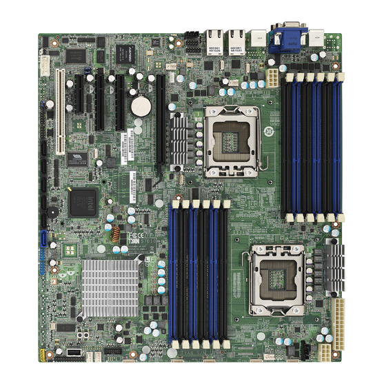
Page 10: Board Image
All manuals and user guides at all-guides.com 2.1 - Board Image S7010 This picture is representative of the latest board revision available at the time of publishing. The board you receive may or may not look exactly like the above picture. -
Page 11: Block Diagram
All manuals and user guides at all-guides.com 2.2 - Block Diagram S7010AGM2NRF http://www.tyan.com... -
Page 12: Board Parts, Jumpers And Connectors
All manuals and user guides at all-guides.com 2.3 - Board Parts, Jumpers and Connectors S7010AGM2NRF This diagram is representative of the latest board revision available at the time of publishing. The board you receive may not look exactly like the above diagram. Jumper Legend ... - Page 13 All manuals and user guides at all-guides.com Jumper/Connector Function Front Panel Connector J17/J19 1394 Front Panel Header (black) J27/J28 USB Front Panel Header (blue) COM2 Connector IPMB Connector Chassis Intrusion Header Intel HD Audio Header Specific Definition Audio Header USB5 Type-A USB Connector CD_IN Connector PSMI Connector...
- Page 14 All manuals and user guides at all-guides.com (from left to right) SATA5/SATA4/SATA3/SATA2/SATA1/SATA0 J35: PSMI Connector Signal Signal SMB_CLK SMB_DAT SMBALERT V3P3 http://www.tyan.com...
- Page 15 All manuals and user guides at all-guides.com FPAUD1 (J6): Specific Definition Audio Header TYAN does not provide cables for this header. Signal Signal MIC_L_IN MIC_R_IN MIC_JD LINE_IN_L LINE_IN_R LINE_IN_JD LINE_OUT_L LINE_OUT_R LINE_OUT_JD FPAUD2 (J4): Intel HD Audio Header TYAN does not provide cables for this header. Signal Signal MIC_L_IN...
- Page 16 All manuals and user guides at all-guides.com http://www.tyan.com...
- Page 17 All manuals and user guides at all-guides.com COM2 (J8): COM2 Connector Signal Signal J44: Standard Front Panel Connector Signal Signal PWRLED+ +3VSB IDLED+ PWRLED- IDLED- HDLED+ WLED- HDLED- PSU_WLED- PWRSW+ LAN1LED+ LAN1LED- RSTSW SMBDAT SMBCLK IDLED_SW INTRD# LAN2LED+ NMI_SW- LAN2LED- NOTE1: +3.3V power rail is IDLED, WLED (Warning LED), LANLED NOTE2: +5V power rail is PWRLED, HDLED...
- Page 18 All manuals and user guides at all-guides.com USB5 http://www.tyan.com...
- Page 19 All manuals and user guides at all-guides.com J9/J14/J39/J40/J42: 4-pin Fan Header Use this header to connect the +12V Tachometer cooling fan to your PWM Control motherboard to keep the +12V system at optimum Tachometer performance levels. PWM Control J46/J47/J48/J49/J50: 8-pin 4096 Fan Header Signal Signal PWM1...
- Page 20 All manuals and user guides at all-guides.com http://www.tyan.com...
- Page 21 All manuals and user guides at all-guides.com J38: ICH SGPIO Header Signal Signal SMBCLK SDATAOUT0 SMBDAT SDATAOUT1 SLOAD SCLOCK J43: SAS SGPIO Header (BTO) Signal Signal SMBCLK SDATAIN SMBDAT SDATAOUT1 SLOAD SCLOCK HD_ERR JP1: Clear CMOS Jumper Use this jumper when you forgot your system/setup password or need to clear system BIOS setting.
-
Page 22: Installing The Processor And Heatsink
All manuals and user guides at all-guides.com 2.4 - Installing the Processor and Heat Sink ® Your S7010 supports the latest processor technologies from Intel . Check the TYAN website for latest processor support: http://www.tyan.com Processor Installation (LGA1366 Socket) The processor should be installed carefully. Make sure you are wearing an antistatic strap and handle the processor as little as possible. - Page 23 All manuals and user guides at all-guides.com Step 4: Close the CPU socket cover (A) and press the CPU socket lever down to secure the CPU (B). Take care when installing the processor as it has very fragile connector pins below the processor that can bend and break if inserted improperly.
-
Page 24: Thermal Interface Material
All manuals and user guides at all-guides.com 2.5 - Thermal Interface Material There are two types of thermal interface materials designed for use with the processors. The most common material comes as a small pad attached to the heat sink at the time of purchase. -
Page 25: Finishing Installing The Heatsink
All manuals and user guides at all-guides.com 2.6 - Finishing Installing the Heat Sink After you have finished installing the heat sink onto the processor and socket, attach the end wire of the fan (which should already be attached to the heat sink) to the motherboard. -
Page 26: Tips On Installing Motherboard In Chassis
All manuals and user guides at all-guides.com 2.7 - Tips on Installing Motherboard in Chassis Before installing your motherboard, make sure your chassis has the necessary motherboard support studs installed. These studs are usually metal and are gold in color. Usually, the chassis manufacturer will pre-install the support studs. If you are unsure of stud placement, simply lay the motherboard inside the chassis and align the screw holes of the motherboard to the studs inside the case. -
Page 27: Installing The Memory
All manuals and user guides at all-guides.com 2.8 - Installing the Memory Before installing memory, ensure that the memory you have is compatible with the motherboard and processor. Check the TYAN Web site at: www.tyan.com for details of the type of memory recommended for your motherboard. The following diagram shows common types of DDR3 memory modules. - Page 28 All manuals and user guides at all-guides.com The following tables outline the suggested rules for populating memory. Table 1 RDIMM population S7010 RDIMM population One DIMMs per Channel Two DIMMs per Channel Single Rank DIMM C0 x(*) x(*) x(*) x(*) x(*) Memory DIMM C1...
- Page 29 All manuals and user guides at all-guides.com Table 2 UDIMM population S7010 UDIMM population One DIMMs per Channel Two DIMMs per Channel Single Rank DIMM C0 Memory DIMM C1 DIMM B0 DIMM B1 DIMM A0 DIMM A1 Dual Rank DIMM C0 x(*) x(*) x(*)
- Page 30 All manuals and user guides at all-guides.com Memory Installation Procedure Follow these instructions to install memory modules into the S7010. 1. Press the locking levers in the direction shown in the following illustration. Align the memory module with the socket. The memory module is keyed to fit only one way in the socket.
-
Page 31: Attaching Drive Cables
All manuals and user guides at all-guides.com 2.9 - Attaching Drive Cables Attaching Serial ATA Cables The S7010 is also equipped with 6 Serial ATA (SATA) channels. Connections for these drives are also very simple. There is no need to set Master/Slave jumpers on SATA drives. TYAN has supplied two SATA cables and one SATA power adapter. -
Page 32: Installing Add-In Cards
All manuals and user guides at all-guides.com 2.10 - Installing Add-In Cards Before installing add-in cards, it’s helpful to know if they are fully compatible with your motherboard. For this reason, we’ve provided the diagrams below, showing the slots that appear on your motherboard. 1 PCI-E x16 slot 2 PCI-E x8 slots 1 PCI-E x4 Slot... -
Page 33: Installing I/O Shield
All manuals and user guides at all-guides.com 2.11 – Installing I/O Shield Before you connect external devices, look into your motherboard package and take out the I/O shield. Follow the following instructions to install the I/O shield to your rear panel. 1. -
Page 34: Connecting External Devices
All manuals and user guides at all-guides.com 2.12 - Connecting External Devices The following diagram will detail the rear port stack for this S7010 motherboard: Top: VGA Port Bottom: Serial Port USB x 2 USB x2 LAN2 (share with IPMI) LAN1 NOTE: Peripheral devices can be plugged straight into any of these ports but software may be required to complete the installation. -
Page 35: Installing The Power Supply
All manuals and user guides at all-guides.com 2.13 - Installing the Power Supply There are four power connectors on your S7010. The S7010 requires 4 power inputs. - 24-pin (PW3) - 8-pin (PW1, PW4) - 4-pin (PW2) 1 x 24-pin 12V Power Connector (PW3) 2 x 8-pin 12V Power Connector (PW1, PW4) 1 x 4-pin 12V/5V Power Connector (PW2, aux. - Page 36 All manuals and user guides at all-guides.com NOTE http://www.tyan.com...
-
Page 37: Chapter 3: Bios Setup
All manuals and user guides at all-guides.com Chapter 3: BIOS Setup About the BIOS The BIOS is the basic input/output system, the firmware on the motherboard that enables your hardware to interface with your software. The BIOS determines what a computer can do without accessing programs from a disk. - Page 38 All manuals and user guides at all-guides.com Setup Basics The table below shows how to navigate in the setup program using the keyboard. Function <F1> General help window <ESC> Exit current menu arrow keys Select a different menu ...
-
Page 39: Bios Main Menu
All manuals and user guides at all-guides.com 3.1 - BIOS Main Menu The Main BIOS Menu is the first screen that you can navigate. The Main BIOS setup menu screen has two main frames. The left frame displays all the options that can be configured. -
Page 40: Advanced Menu
All manuals and user guides at all-guides.com 3.2 - Advanced Menu You can select any of the items in the left frame of the screen, such as Super I/O Configuration, to go to the sub menu for that item. You can display an Advanced BIOS Setup option by highlighting it using the <Arrow>... - Page 41 All manuals and user guides at all-guides.com Feature Option Description Advanced Settings Configure I/O virtualization I/O Virtualization Menu Item parameters IPMI configuration including server IPMI 2.0 Configuration Menu Item monitoring and event log ® Configure Intel Virtualization Intel VT-d Configuration Menu Item Technology for Directed I/O (VT-d) support...
- Page 42 All manuals and user guides at all-guides.com 3.2.1 CPU Configuration You can use this screen to view CPU Configuration Menu. Use the up and down arrow (/) keys to select an item. Use the Plus and Minus (+/-) keys to change the value of the selected option.
- Page 43 All manuals and user guides at all-guides.com Feature Option Description CPU Configuration Manufacturer ® Intel Frequency Read only Displays information about CPU BCLK Speed Cache L1/L2/L3 Ratio Status Ratio Actual Value Sets the ratio between CPU Core Clock According to CPU and the FSB Frequency.
- Page 44 All manuals and user guides at all-guides.com Feature Option Description CPU Configuration Enabled Execute-Disable Bit When disabled, force the XD feature Capability flag to always return 0. Disabled Enabled When disabled, only one thread per ® Intel HT Technology enabled core is enabled. Disabled Number of cores to enable in each Active Processor Cores...
- Page 45 All manuals and user guides at all-guides.com 3.2.2 IDE Configuration Sub-Menu You can use this screen to select options for the IDE Configuration Settings. Use the up and down <Arrow> keys to select an item. Use the <Plus> and <Minus> keys to change the value of the selected option.
- Page 46 All manuals and user guides at all-guides.com 3.2.2.1 SATA0/1/2/3/4/5 Sub-Menu BIOS Setup Utility Main Advanced PCI/PnP Boot Security Chipset Exit SATA0 Selects the type of device connected to the system. Device: Not Detected ← → Select Screen Type [Auto] ↑↓ Select Item LBA /Large Mode [Auto] Change Option...
- Page 47 All manuals and user guides at all-guides.com 3.2.3 Super IO Configuration Sub-Menu You can use this screen to select options for the Super I/O settings. Use the up and down arrow (/) keys to select an item. Use the Plus and Minus (+/-) keys to change the value of the selected option BIOS Setup Utility Main...
- Page 48 All manuals and user guides at all-guides.com 3.2.4 USB Configuration Sub-Menu You can use this screen to view the USB Configuration Menu. Use the up and down arrow (/) keys to select an item. Use the Plus and Minus (+/-) keys to change the value of the selected option.
- Page 49 All manuals and user guides at all-guides.com 3.2.4.1 – USB Mass Storage Device Configuration Sub-Menu BIOS Setup Utility Main Advanced PCI/PnP Boot Security Chipset Exit USB Mass Storage Device Configuration Number of seconds POST waits for the USB mass storage device after start USB Mass Storage Reset Delay [20 Sec] unit command...
- Page 50 All manuals and user guides at all-guides.com 3.2.5 ACPI Configuration Sub-Menu Use this screen to select options for ACPI. Use the up and down arrow (/) keys to select an item. Use the Plus and Minus (+/-) keys to change the value of the selected option.
- Page 51 All manuals and user guides at all-guides.com 3.2.5.1 General ACPI Configuration Sub-Menu BIOS Setup Utility Main Advanced PCI/PnP Boot Security Chipset Exit Select the ACPI state used General ACPI Configuration for System Suspend. Suspend Mode [S1(POS)] ← → Select Screen Repost video on S3 Resume [No] ↑↓...
- Page 52 All manuals and user guides at all-guides.com 3.2.5.2 Advanced ACPI Configuration Sub-Menu BIOS Setup Utility Main Advanced PCI/PnP Boot Security Chipset Exit Enable RSDP pointers to Advanced ACPI Configuration 64-bit Fixed System Description Tables. Di ACPI version has some. ACPI Version Features [ACPI v3.0] ACPI APIC support [Enabled]...
- Page 53 All manuals and user guides at all-guides.com 3.2.5.3 Chipset ACPI Configuration Sub-Menu BIOS Setup Utility Main Advanced PCI/PnP Boot Security Chipset Exit Options South Bridge ACPI Configuration Enabled Disabled Energy Lake Feature [Disabled] ← → Select Screen ACPI APIC SCI IRQ [Disabled] High Performance Event Timer [Enabled]...
- Page 54 All manuals and user guides at all-guides.com 3.2.6 AHCI Configuration Sub-Menu You can use this screen to view the AHCI Configuration Menu. Use the up and down arrow (/) keys to select an item. Use the Plus and Minus (+/-) keys to change the value of the selected option.
- Page 55 All manuals and user guides at all-guides.com 3.2.6.1 AHCI Port0/Port1/Port2/Port3/Port4/Port5 Sub-Menu BIOS Setup Utility Main Advanced PCI/PnP Boot Security Chipset Exit AHCI Port0 Select the type of device connected to the system. Device: Not Detected ← → Select Screen ↑↓ Select Item SATA Port0 [Auto] Change Option...
- Page 56 All manuals and user guides at all-guides.com 3.2.7 Hardware Health Configuration Sub-Menu You can use this screen to view the Hardware Health Configuration Settings. Use the up and down arrow (/) keys to select an item. Use the Plus and Minus (+/-) keys to change the value of the selected option.
- Page 57 All manuals and user guides at all-guides.com Main Advanced PCI/PnP Boot Security Chipset Exit NAME READING STATUS CPU1 below Tmax : xx CPU0 below Tmax : xx PCI Area 1 (RT2) : xx PCI Area 2 (RT4) : xx CPU1 VCORE : x.xxx V CPU0 VCORE : x.xxx V...
- Page 58 All manuals and user guides at all-guides.com 3.2.7.1 Memory Temperature Sensor Monitoring Sub-Menu Main Advanced PCI/PnP Boot Security Chipset Exit Channel A Temperature (CPU0): N/A ← → Select Screen Channel B Temperature (CPU0): N/A ↑↓ Select Item Channel C Temperature (CPU0): N/A Change Option Channel A Temperature (CPU1): N/A Tab Select Field...
- Page 59 All manuals and user guides at all-guides.com 3.2.8 I/O Virtualization Sub-Menu You can use this screen to select the I/O Virtualization Menu. Use the up and down arrow (/) keys to select an item. Use the Plus and Minus (+/-) keys to change the value of the selected option.
- Page 60 All manuals and user guides at all-guides.com 3.2.9 IPMI 2.0 Configuration Sub-Menu You can use this screen to view the IPMI 2.0 Configuration Settings. Use the up and down arrow (/) keys to select an item. Use the Plus and Minus (+/-) keys to change the value of the selected option.
- Page 61 All manuals and user guides at all-guides.com 3.2.9.1 View BMC System Event Log Sub-Menu BIOS Setup Utility Main Advanced PCI/PnP Boot Security Chipset Exit Total Number of Entries: 260 Use +/- to traverse the event log. SEL Entry Number SEL Record ID xxxx ←...
- Page 62 All manuals and user guides at all-guides.com 3.2.9.2.1 Setup LAN Configuration BIOS Setup Utility Main Advanced PCI/PnP Boot Security Chipset Exit Setup LAN Configuration IPMI IP Address Source STATIC / DHCP IP Address Configuration [DHCP] After setup LAN Configure IP Address [000.000.000.000] need select Save LAN Subnet Mask...
- Page 63 All manuals and user guides at all-guides.com 3.2.9.2 Set VLAN Configuration BIOS Setup Utility Main Advanced PCI/PnP Boot Security Chipset Exit Setup VLAN ID Configuration Press Enter and [OK] to save LAN configure Select Screen Current VLAN ID Status [Disabled] ←...
- Page 64 All manuals and user guides at all-guides.com 3.2.9.4 Set PEF Configuration Sub-Menu BIOS Setup Utility Main Advanced PCI/PnP Boot Security Chipset Exit Set PEF Configuration Parameters Command Enable or Disable PEF Support ← → Select Screen PEF Support [Disabled] ↑↓ Select Item Change Option Tab Select Field General Help...
- Page 65 All manuals and user guides at all-guides.com 3.2.10 Intel VT-d Configuration Sub-Menu You can use this screen to view the Intel VT-d Configuration Settings. Use the up and down arrow (/) keys to select an item. Use the Plus and Minus (+/-) keys to change the value of the selected option.
- Page 66 All manuals and user guides at all-guides.com 3.2.11 PCI Express Configuration Sub-Menu You can use this screen to configure the PCI Express Support. Use the up and down arrow (/) keys to select an item. Use the Plus and Minus (+/-) keys to change the value of the selected option.
- Page 67 All manuals and user guides at all-guides.com 3.2.12 Remote Access Configuration Sub-Menu You can use this screen to view the Remote Access Configuration Menu. This feature allows access to the Server remotely via serial port. Use the up and down arrow (/) keys to select an item.
- Page 68 All manuals and user guides at all-guides.com Feature Option Description Configure Remote Access type and parameters Disable: Turns off the redirection after Disabled POST Boot Loader: Redirection is active during POST and during Boot Loader. Redirection After BIOS POST Boot Loader Always: Redirection is always active.
- Page 69 All manuals and user guides at all-guides.com 3.2.13 Trusted Computing Sub-Menu You can use this screen to view the Trusted Computing Configuration Menu. Use the up and down arrow (/) keys to select an item. Use the Plus and Minus (+/-) keys to change the value of the selected option.
- Page 70 All manuals and user guides at all-guides.com 3.2.14 Onboard Devices Configuration Sub-Menu You can use this screen to view the Onboard Devices Configuration Menu. Use the up and down arrow (/) keys to select an item. Use the Plus and Minus (+/-) keys to change the value of the selected option.
-
Page 71: Pci Pnp Menu
All manuals and user guides at all-guides.com 3.3 - PCI PnP Menu You can use this screen to view PnP (Plug & Play) BIOS Configuration Menu. This menu allows the user to configure how the BIOS assigns resources & resolves conflicts. - Page 72 All manuals and user guides at all-guides.com Yes: assigns IRQ to PCI VGA card if Allocate IRQ to PCI VGA card requests IRQ. This is the default setting and should not be changed unless the VGA card Disabled manufacturer requires Palette Snooping to be Enabled.
-
Page 73: Boot Menu
All manuals and user guides at all-guides.com 3.4 - Boot Menu You can display Boot Setup option by highlighting it using the Arrow (/) keys and pressing Enter. The settings are described on the following pages. BIOS Setup Utility Main Advanced PCI/PnP Boot... - Page 74 All manuals and user guides at all-guides.com Feature Option Description Boot Settings Configuration Enabled This option allows user bypass BIOS self Quick Boot test during POST. Disabled Disabled: displays normal POST Disabled messages. Quiet Boot Enabled: displays OEM log instead of Enabled POST messages.
- Page 75 All manuals and user guides at all-guides.com 3.4.2 Boot Device Priority Use this screen to select options for the Boot Device Priority. Use the up and down arrow (/) keys to select an item. Use the Plus and Minus (+/-) keys to change the value of the selected option.
- Page 76 All manuals and user guides at all-guides.com 3.4.3 Hard Disk Drives Use this screen to select options for the Hard Disk Drives. Use the up and down arrow (/) keys to select an item. Use the Plus and Minus (+/-) keys to change the value of the selected option.
-
Page 77: Security Menu
All manuals and user guides at all-guides.com 3.5 - Security Menu The system can be configured so that all users must enter a password every time the system boots or when BIOS Setup is entered, using either the Supervisor password or User password. The Supervisor and User passwords activate two different levels of password security. -
Page 78: Chipset Menu
All manuals and user guides at all-guides.com 3.6 - Chipset Menu This menu allows the user to customize functions of the Intel Chipsets. Select a menu by highlighting it using the Arrow (/) keys and pressing Enter. The settings are described on the following pages. BIOS Setup Utility Main Advanced... - Page 79 All manuals and user guides at all-guides.com 3.6.1 CPU Bridge Configuration Sub-Menu This menu gives options for customizing CPU Bridge Chipset settings. Select a menu by highlighting it using the Arrow (/) keys and pressing Enter. The settings are described on the following pages. BIOS Setup Utility Main Advanced...
- Page 80 All manuals and user guides at all-guides.com 3.6.2 North Bridge Configuration Sub-Menu This menu gives options for customizing North Bridge Chipset settings. Select a menu by highlighting it using the Arrow (/) keys and pressing Enter. The settings are described on the following pages. BIOS Setup Utility Main Advanced...
- Page 81 All manuals and user guides at all-guides.com 3.6.3 South Bridge Configuration Sub-Menu This menu gives options for customizing South Bridge Chipset settings. Select a menu by highlighting it using the Arrow (/) keys and pressing Enter. The settings are described on the following pages. BIOS Setup Utility Main Advanced...
- Page 82 All manuals and user guides at all-guides.com 3.6.4 ME Subsystem Configuration Sub-Menu This menu provides selection for ME subsystem configuration. Select a menu by highlighting it using the Arrow (/) keys and pressing Enter. The settings are described on the following pages. BIOS Setup Utility Main Advanced...
-
Page 83: Exit Menu
All manuals and user guides at all-guides.com 3.7 - Exit Menu You can display an Exit BIOS Setup option by highlighting it Arrow (/) keys and pressing Enter. BIOS Setup Utility Main Advanced PCI/PnP Boot Security Chipset Exit Exit system setup after Exit Options saving the changes. - Page 84 All manuals and user guides at all-guides.com NOTE http://www.tyan.com...
-
Page 85: Chapter 4: Diagnostics
All manuals and user guides at all-guides.com Chapter 4: Diagnostics NOTE: if you experience problems with setting up your system, always check the following things in the following order: Memory, Video, CPU By checking these items, you will most likely find out what the problem might have been when setting up your system. -
Page 86: Amibios Post Code
All manuals and user guides at all-guides.com 4.3 - AMIBIOS Post Code The POST code checkpoints are the largest set of checkpoints during the BIOS pre- boot process. The following table describes the type of checkpoints that may occur during the POST portion of the BIOS: Checkpoint Description Disable NMI, Parity, video for EGA, and DMA controllers. - Page 87 All manuals and user guides at all-guides.com Checkpoint Description Initializes DMAC-1 & DMAC-2. Initialize RTC date/time. Test for total memory installed in the system. Also, Check for DEL or ESC keys to limit memory test. Display total memory in the system. Mid POST initialization of chipset registers.
- Page 88 All manuals and user guides at all-guides.com NOTE http://www.tyan.com...
-
Page 89: Glossary
All manuals and user guides at all-guides.com Glossary ACPI (Advanced Configuration and Power Interface): a power management specification that allows the operating system to control the amount of power distributed to the computer’s devices. Devices not in use can be turned off, reducing unnecessary power expenditure. - Page 90 All manuals and user guides at all-guides.com Bus: a data pathway. The term is used especially to refer to the connection between the processor and system memory, and between the processor and PCI or ISA local buses. Bus mastering: allows peripheral devices and IDEs to access the system memory without going through the CPU (similar to DMA channels).
- Page 91 All manuals and user guides at all-guides.com IRQs, it is vital that you do not double up devices on a single line. Plug-n-Play devices will take care of this for you. Doze mode: in this mode, only the CPU’s speed is slowed. DRAM (Dynamic RAM): widely available, very affordable form of RAM which has the unfortunate tendency to lose data if it is not recharged regularly (every few milliseconds).
- Page 92 All manuals and user guides at all-guides.com I/O (Input/Output): the connection between your computer and another piece of hardware (mouse, keyboard, etc.) Initial Program Load (IPL): a feature built into BBS-compliant devices, describing those devices as capable of loading and executing an OS, as well as being able to provide control back to the BIOS if the loading attempt fails.
- Page 93 All manuals and user guides at all-guides.com PM timers (Power Management timers): software timers that count down the number of seconds or minutes until the system times out and enters sleep, suspend, or doze mode. PnP (Plug-n-Play): a design standard that has become ascendant in the industry. Plug-n-Play devices require little set-up to use.
- Page 94 All manuals and user guides at all-guides.com associated with non-synchronous RAM, which must close one address bank before opening the next. Serial port: called as such because it transmits the eight bits of a byte of data along one wire, and receives data on another single wire (that is, the data is transmitted in serial form, one bit after another).
-
Page 95: Technical Support
All manuals and user guides at all-guides.com Technical Support If a problem arises with your system, you should turn to your dealer for help first. Your system has most likely been configured by them, and they should have the best idea of what hardware and software your system contains. Furthermore, if you purchased your system from a dealer near you, you can bring your system to them to have it serviced instead of attempting to do so yourself (which can have expensive consequences). - Page 96 All manuals and user guides at all-guides.com radio or television reception, which can be determined by turning the equipment off and on, the user is encouraged to try one or more of the following measures: Reorient or relocate the receiving antenna. Increase the separation between the equipment and the receiver.
Need help?
Do you have a question about the TYAN S7010 and is the answer not in the manual?
Questions and answers