Table of Contents
Advertisement
Quick Links
S7103
Version 1.0c
Copyright
Copyright © 2018 MITAC COMPUTING TECHNOLOGY CORPORATION. All rights
reserved. No part of this manual may be reproduced or translated without prior
written consent from MITAC COMPUTING TECHNOLOGY CORPORATION.
Trademark
All registered and unregistered trademarks and company names contained in this
manual are property of their respective owners including, but not limited to the
following.
®
TYAN
is a trademark of MITAC COMPUTING TECHNOLOGY CORPORATION.
®
®
Intel
is a trademark of Intel
Corporation.
AMI, AMI BIOS are trademarks of AMI Technologies.
Microsoft
®
, Windows
®
are trademarks of Microsoft Corporation.
®
Nuvoton
is a trademark of Nuvoton Technology Corporation.
Notice
Information contained in this document is furnished by MITAC COMPUTING
TECHNOLOGY CORPORATION and has been reviewed for accuracy and reliability
prior to printing. MITAC assumes no liability whatsoever, and disclaims any express
®
or implied warranty, relating to sale and/or use of TYAN
products including liability
or warranties relating to fitness for a particular purpose or merchantability. MITAC
retains the right to make changes to product descriptions and/or specifications at
any time, without notice. In no event will MITAC be held liable for any direct or
indirect, incidental or consequential damage, loss of use, loss of data or other
malady resulting from errors or inaccuracies of information contained in this
document.
1
http://www.tyan.com
Advertisement
Table of Contents

Subscribe to Our Youtube Channel
Related Manuals for MiTAC TYAN S7103


Summary of Contents for MiTAC TYAN S7103
- Page 1 In no event will MITAC be held liable for any direct or indirect, incidental or consequential damage, loss of use, loss of data or other malady resulting from errors or inaccuracies of information contained in this document.
- Page 2 http://www.tyan.com...
-
Page 3: Table Of Contents
Contents Before you begin… ..................4 Chapter 1: Instruction ................5 1.1 Congratulations ................. 5 1.2 Hardware Specifications ..............5 1.3 Software Specifications ..............20 Chapter 2: Board Installation ..............21 2.1 Board Image ..................22 ... -
Page 4: Before You Begin
Before you begin… Check the box contents! The retail motherboard package should contain the following: 1 x S7103 Motherboard 2 x CPU clip for Narrow Non-Fabric CPU Carrier 2 x SATA Cable 1 x Rear IO Shield 1 x S7103 Quick reference guide ®... -
Page 5: Chapter 1: Instruction
® find all the information on all TYAN products as well as all the supporting documentation, FAQs, Drivers and BIOS upgrades. 1.2 Hardware Specifications TYAN S7103 (S7103GM2NR) Socket Type / Q'ty LGA3647/ (2) Supported CPU Series Intel Xeon Scalable Processor... - Page 6 IPMI Controller Intel I350-AM2 Realtek RTL8211E Connector (2) Mini-SAS (8-ports) Controller Intel C621 SATA Speed 6.0 Gb/s RAID RAID 0/1/10/5 (Intel RSTe) Storage (1) Mini-SAS (4-ports), Connector (2) SATA/SATA-DOM Controller Intel C621 sSATA Speed 6.0 Gb/s RAID RAID 0/1/10/5 (Intel RSTe) Connector type D-Sub 15-pin Graphic...
- Page 7 Please refer to our AVL support lists. Motherboard (1) S7103 Motherboard Package Contains Manual (1) Quick Installation Guide Installation CD (1) TYAN Device Driver CD TYAN S7103 (S7103WGM2NR) Socket Type / Q'ty LGA3647/ (2) Supported CPU Intel Xeon Scalable Processor Series Thermal Design Processor...
- Page 8 DDR4 ECC RDIMM/LRDIMM DIMM Type / Speed 2666/2400/2133 Up to 384GB RDIMM/768GB Capacity LRDIMM *Follow latest Intel DDR4 Memory POR Memory channel 6 Channels per CPU Memory voltage 1.2V (2) PCI-E Gen3 x16 slots, (5) PCI-E Expansion Slots PCI-E Gen3 x8 slots (2) GbE ports, (1) PHY dedicated Port Q'ty for IPMI...
- Page 9 RJ-45 (2) GbE ports, (1) Dedicated for IPMI Front Panel (1) 2x12-pin SSI front panel header (2) Mini-SAS (4-in-1) connectors (2) SATA/SATA-DOM connectors + SATA (3) Mini-SAS (4-in-1) connectors SSI/ATX 24-pin + 8-pin power Power connectors Others (1) ID button Please refer to our TPM supported TPM (Optional) TPM Support...
- Page 10 Motherboard (1) S7103 Motherboard Package Contains Manual (1) Quick Installation Guide Installation CD (1) TYAN Device Driver CD TYAN S7103 (S7103GM4NR-2F-L2) Socket Type / Q'ty LGA3647/ (2) Supported CPU Intel Xeon Scalable Processor Series Thermal Design Processor Max up to 205W Power (TDP) wattage Up to 10.4/9.6 GT/s with Intel...
- Page 11 Speed 6.0 Gb/s RAID 0/1/10/5 (Intel RAID RSTe) (1) Mini-SAS (4-ports), Connector (2) SATA/SATA-DOM Controller Intel C622 sSATA Speed 6.0 Gb/s RAID 0/1/10/5 (Intel RAID RSTe) Connector type D-Sub 15-pin Graphic Resolution Up to 1920x1200 Chipset Aspeed AST2500 (2) USB3.0 ports (via cable), (2) USB3.0 ports (at rear), (1) Type-A USB3.0 port (1) DB-9 COM Connector...
- Page 12 Motherboard (1) S7103 Motherboard Package Contains Manual (1) Quick Installation Guide Installation CD (1) TYAN Device Driver CD TYAN S7103 (S7103WGM4NR-2F-L2) Socket Type / Q'ty LGA3647/ (2) Supported CPU Intel Xeon Scalable Processor Series Thermal Design Processor Max up to 205W Power (TDP) wattage Up to 10.4/9.6 GT/s with Intel...
- Page 13 Chipset Intel C622 Supported DIMM Qty (6)+(6) DIMM slots DDR4 ECC RDIMM/LRDIMM DIMM Type / Speed 2666/2400/2133 Up to 384GB RDIMM/768GB Memory Capacity LRDIMM *Follow latest Intel DDR4 Memory POR Memory channel 6 Channels per CPU Memory voltage 1.2V (2) PCI-E Gen3 x16 slots, (5) PCI-E Expansion Slots PCI-E Gen3 x8 slots...
- Page 14 USB3.0 port (1) DB-9 COM Connector (1) D-Sub 15-pin VGA port (at rear) RJ-45 (2) GbE ports, (1) Dedicated for IPMI Front Panel (1) 2x12-pin SSI front panel header (2) SATA/SATA-DOM connectors + SATA (3) Mini-SAS (4-in-1) connectors SSI/ATX 24-pin + 8-pin power Power connectors SFP+...
- Page 15 Motherboard (1) S7103 Motherboard Package Contains Manual (1) Quick Installation Guide Installation CD (1) TYAN Device Driver CD TYAN S7103 (S7103GM2NR-2F-L2) Socket Type / Q'ty LGA3647/ (2) Supported CPU Intel Xeon Scalable Processor Series Thermal Design Processor Max up to 205W Power (TDP) wattage Up to 10.4/9.6 GT/s with Intel...
- Page 16 Realtek RTL8211E Connector (2) Mini-SAS (8-ports) Controller Intel C622 SATA Speed 6.0 Gb/s RAID 0/1/10/5 (Intel RAID RSTe) Storage (1) Mini-SAS (4-ports), Connector (2) SATA/SATA-DOM Controller Intel C622 sSATA Speed 6.0 Gb/s RAID 0/1/10/5 (Intel RAID RSTe) Connector type D-Sub 15-pin Graphic Resolution Up to 1920x1200...
- Page 17 OS supported list lists. Motherboard (1) S7103 Motherboard Package Contains Manual (1) Quick Installation Guide Installation CD (1) TYAN Device Driver CD TYAN S7103 (S7103WGM2NR-2F-L2) Socket Type / Q'ty LGA3647/ (2) Processor Supported CPU Intel Xeon Scalable Processor Series http://www.tyan.com...
- Page 18 Thermal Design Max up to 205W Power (TDP) wattage Up to 10.4/9.6 GT/s with Intel System Bus UltraPath Interconnect (UPI) support Chipset Intel C622 Supported DIMM Qty (6)+(6) DIMM slots DDR4 ECC RDIMM/LRDIMM DIMM Type / Speed 2666/2400/2133 Up to 384GB RDIMM/ 768GB Memory Capacity LRDIMM *Follow latest Intel DDR4...
- Page 19 Resolution Up to 1920x1200 Chipset Aspeed AST2500 (2) USB3.0 ports (via cable), (2) USB3.0 ports (at rear), (1) Type-A USB3.0 port (1) DB-9 COM Connector (1) D-Sub 15-pin VGA port (at rear) RJ-45 (1) GbE port dedicated for IPMI Input /Output Front Panel (1) 2x12-pin SSI front panel header (2) SATA/SATA-DOM connectors +...
-
Page 20: Software Specifications
FAN PWM Duty Cycle, Console Redirection, ACPI sleeping states S0,S1,S5 Form Factor EATX Physical Dimension Board Dimension 12"x13" (305x330mm) FCC (DoC) Class A Regulation CE (DoC) Class A Operating Temp. 10° C ~ 35° C (50° F~ 95° F) Non-operating Temp. - 40° C ~ 70° C (-40° F ~ 158° F) Operating Environment In/Non-operating 90%, non-condensing at 35°... -
Page 21: Chapter 2: Board Installation
Unplug the power from your computer power supply and then touch a safely grounded object to release static charge (i.e. power supply case). For the safest conditions, MITAC recommends wearing a static safety wrist strap. (2) Hold the motherboard by its edges and do not touch the bottom of the board, or flex the board in any way. -
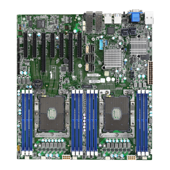
Page 22: Board Image
2.1 Board Image S7103WGM4NR-2F-L2 This picture is representative of the latest board revision available at the time of publishing. The board you receive may not look exactly like the above picture. http://www.tyan.com... -
Page 23: Block Diagram
2.2 Block Diagram S7103 Block Diagram http://www.tyan.com... -
Page 24: Mainboard Mechanical Drawing
2.3 Mainboard Mechanical Drawing http://www.tyan.com... -
Page 25: Board Parts, Jumpers And Connectors
2.4 Board Parts, Jumpers and Connectors This diagram is representative of the latest board revision available at the time of publishing. The board you receive may not look exactly like the above diagram. But for the DIMM number please refer to the above placement for memory installation. For the latest board revision, please visit our web site at http://www.tyan.com. - Page 26 Jumpers & Connectors Connectors 1. RJ45 LAN Port + USB3.0 Dual Ports 19. SSATA SGPIO Connector (USB3_IPMI_LAN1) (SSATA_GPIO1) 20. SATA DOM Connector 2. VGA Port / COM1 Port (VGA_COM1) (SSATA_DOM1) 3. Mini SAS (Vertical) Connector (Mini_SAS2) (optional, not available for 21.
- Page 27 PCIE Slots (x8) (PCIe_slot3) PCIE Slots (x16) (PCIe_slot2) PCIE Slots (x8) (PCIe_slot1) Jumper Legend OPEN - Jumper OFF Without jumper cover CLOSED - Jumper ON With jumper cover http://www.tyan.com...
- Page 28 SYS_FAN_1~5 / CPU0_FAN / CPU1_FAN: 4-pin FAN Connector Signal +12V TACH Use this header to connect the cooling fan to your motherboard to keep the system stable and reliable. FPIO_1: Front Panel Header Signal Signal PWRLED+ VCC3_AUX IDLED+ PWRLED- IDLED- HDDLED+ SYS_FAULT1- HEELED-...
- Page 29 PSMI1: PSMI Connector Signal Signal SMB_CLK SMB_DAT SMB_ALERT# VCC3 DBG_HD1: TYAN Module Header Signal Signal VCC3 FRAME LAD0 LAD1 RESET# LAD2 LAD3 SERIRQ PRSNT# 3VSB GPIO1 GPIO2 IPMB_HD1: IPMB Pin Header Signal Signal BMC_SMB_DATA BMC_SMB_CLK USB3_FPIO1: USB3.0 Header Signal Signal P0_RX_N P0_RX_P P1_RX_N...
- Page 30 FAN_HDR1: Fan Connector Reserved for Barebone Signal Signal FAN_T1 FAN_T6 FAN_T2 FAN_T7 FAN_T3 FAN_T8 FAN_T4 FAN_T9 FAN_T5 FAN_T10 PWM_REAR12 PWM_FRONT3 FAN_T11 FAN_SDA FAN_T12 FAN_SCK VCC3_AUX PWM_BB3 SSATA_SGPIO1: SSATA SGPIO Pin Header Signal Signal SDIN DATA SDOUT SLOAD SCLOCK VCC3_AUX HDD_FAULT SSATA_DOM0 / SSATA_DOM1: SSATA DOM Connector Signal Signal...
- Page 31 ® J1: VROC Header (full featured RAID 0, 1, 10, 5, using Intel VROC, for NVMe SSD SKU) Signal VCC3_AUX PCH_SATA_RAID_KEY Clear_BTN1: RTC Reset Button for Clear CMOS You can reset the CMOS settings by using this button, if you have forgotten your system/setup password or need to clear system BIOS setting.
-
Page 32: Installing The Processor And Heat Sink
Specifications on page 5. Check our website at http://www.tyan.com for latest processor support. NOTE: MITAC TYAN is not liable for damage as a result of operating an unsupported configuration. Processor Installation for LGA3647 Socket Follow the steps below to install the processors and heat sinks. NOTE: Please save and replace the CPU protection cap when returning for service. - Page 33 Remove the CPU cover. NOTE: Save and replace the CPU cover if the processor is removed from its socket. Align the heatsink with the CPU socket by the guide pins and make sure the gold arrow is located in the correct direction. Then place the heatsink onto the top of the CPU socket.
- Page 34 To secure the heatsink, use a T30 Security Torx to tighten the screws in a sequential order (1234). NOTE: When disassembling the heatsink, loosen the screws in reverse order (4321). NOTE: Always check with the manufacturer of the heat sink & processor to ensure that the thermal interface material is compatible with the processor and meets the manufacturer’s warranty requirements.
-
Page 35: Tips On Installing Motherboard In Chassis
Some chassis include plastic studs instead of metal. Although the plastic studs are usable, MITAC recommends using metal studs with screws that will fasten the motherboard more securely in place. http://www.tyan.com... - Page 36 Below is a chart detailing what the most common motherboard studs look like and how they should be installed. http://www.tyan.com...
-
Page 37: Installing The Memory
2.8 Installing the Memory Before installing memory, ensure that the memory you have is compatible with the motherboard and processor. Check the TYAN Web site at http://www.tyan.com details of the type of memory recommended for your motherboard. Supports single/dual rank memory ... - Page 38 Recommended Memory Population Table (Single CPU) Single CPU Installed (CPU0 only) Quantity of memory installed P0_MCO_DIM_CH_A0 √ √ √ √ √ √ P0_MCO_DIM_CH_B0 √ √ √ √ √ P0_MCO_DIM_CH_C0 √ √ √ √ P0_MCO_DIM_CH_D0 √ √ √ P0_MCO_DIM_CH_E0 √ √ P0_MCO_DIM_CH_F0 √...
- Page 39 Memory Installation Procedure Follow these instructions to install memory modules into the S7103. Unlock the clips as shown in the illustration. Insert the memory module firmly into the socket by gently pressing down until it sits flush with the socket. Lock the clips to secure the memory module into place.
-
Page 40: Attaching Drive Cables
2.9 Attaching Drive Cables Attaching Serial ATA Cables S7103 is equipped with six (6) Serial ATA (SATA) channel. Connections for the drives are very simple. There is no need to set Master/Slave jumpers on SATA drives. If you are in need of SATA/SAS cables or power adapters please contact your place of purchase. -
Page 41: Installing Add-In Cards
2.10 Installing Add-In Cards Before installing add-in cards, it’s helpful to know if they are fully compatible with your motherboard. For this reason, we’ve provided the diagrams below, showing the slots that may appear on your motherboard. PCI-E x16 slot PCI-E x8 slot Simply find the appropriate slot for your add-in card and insert the card firmly. -
Page 42: Connecting External Devices
2.11 Connecting External Devices Connecting external devices to the motherboard is an easy task. The motherboard supports a number of different interfaces through connecting peripherals. See the following diagrams for the details. NOTE: 1. Peripheral devices can be plugged straight into any of these ports but software may be required to complete the installation. -
Page 43: Installing The Power Supply
2.13 Installing the Power Supply There are three (3) power connectors on your S7103 motherboard. The S7103 supports EPS 12V power supply. PW1: ATX 24-pin Main Power Connector Signal Signal VCC3 VCC3 VCC3 -12V VCC5 PS_ON# VCC5 PWR_OK 5VSB VCC5 VCC12 VCC5 VCC12... -
Page 44: Finishing Up
2.14 Finishing Up Congratulations on making it this far! You have finished setting up the hardware aspect of your computer. Before closing up your chassis, make sure that all cables and wires are connected properly, especially IDE cables and most importantly, jumpers. -
Page 45: Chapter 3: Bios Setup
Chapter 3: BIOS Setup 3.1 About the BIOS The BIOS is the basic input/output system, the firmware on the motherboard that enables your hardware to interface with your software. The BIOS determines what a computer can do without accessing programs from a disk. The BIOS contains all the code required to control the keyboard, display screen, disk drives, serial communications, and a number of miscellaneous functions. - Page 46 Chipset section unless you are absolutely sure of what you are doing. The Chipset defaults have been carefully chosen either by MITAC or your system manufacturer for best performance and reliability. Even a seemingly small change to the Chipset setup options may cause the system to become unstable or unusable.
-
Page 47: Main Menu
3.2 Main Menu In this section, you can alter general features such as the date and time. Note that the options listed below are for options that can directly be changed within the Main Setup screen. System Date Set the Date. Use Tab to switch between Date elements. Default Ranges: Year: 2005-2099 Months: 1-12 Days: dependent on month... -
Page 48: Advanced Menu
3.3 Advanced Menu This section facilitates configuring advanced BIOS options for your system. iSCSI Configuration Configure the iSCSI parameters. Intel® Virtual RAID on CPU This formset allows the user to manage Intel® Virtual RAID on CPU. Trusted Computing Trusted Computing Settings. ACPI Settings System ACPI Parameters. - Page 49 AST2500 Super IO Configuration System Super IO Chip Parameters. S5 RTC Wake Settings Enable system to wake from S5 using RTC alarm. Serial Port Console Redirection Serial Port Console Redirection. Option ROM Dispatch Policy Option ROM Dispatch Policy. PCI Subsystem Settings PCI, PCI-X and PCI Express Settings.
- Page 50 3.3.1 iSCSI Configuration Please follow the instructions to initiate the iSCSI function. Step 1. Select Advanced CSM Configuration Network [UEFI]. Step 2. Select Advanced Network Stack Configuration Network Stack [Enabled] Step 3. Save changes and reboot. iSCSI Initiator Name The worldwide unique name of iSCSI Initiator.
- Page 51 3.3.1.1 Add an Attempt Read only. NOTE: Only LAN1 supports iSCSI function. http://www.tyan.com...
- Page 52 3.3.1.1.1 MAC 34:12:78:56:00:00 iSCSI Mode Disabled, Enabled, Enabled for MPIO. Disabled / Enabled / Enabled for MPIO Internet Protocol Initiator IP address is system assigned in IP6 mode. In Autoconfigure mode, iSCSI driver will attempt to connect iSCSI target via IPv4 stack, if failed then attempt IPv6 stack.
- Page 53 Configure ISID OUI-format ISID in 6 bytes, default value is derived from MAC address. Only last 3 bytes are configurable. Example: update 0ABBCCDDEEFF to OABBCCF07901 by input F07901. Enable DHCP Enable DHCP. Disabled / Enabled Initiator IP Address Enter IP address in dotted-decimal notation. Initiator Subnet Mask Enter IP address in dotted-decimal notation.
- Page 54 3.3.1.2 Delete Attempts Attempt 1 MAC: 34:12:78:56:00:00, PFA: Bus 1/ Dev 0 / Func 0, iSCSI mode: Disabled, IP version: IP4. Disabled / Enabled Commit Changes and Exit Commit Changes and Exit. Discard Changes and Exit Discard Changes and Exit. http://www.tyan.com...
- Page 55 3.3.1.3 Change Attempt Order Change Attempt Order Change the order of Attempts using +/- keys. Use arrow keys to select the attempt then press +/- to move the attempt up/down in the attempt order list. Attempt 1 / Attempt # Commit Changes and Exit Commit Changes and Exit.
- Page 56 3.3.2 Intel® Virtual RAID on CPU Please follow the instructions to initiate the Intel Virtual RAID on CPU function. Step 1. Select Socket Configuration IIO Configuration Intel® VMD technology Intel® VMD for Volume Management Device on Socket 0 (for CPU0) / Socket 1 (for CPU1) ...
- Page 57 3.3.2.1 All Intel VMD Controllers Create RAID Volume This page allows you to create a RAID volume. Non-RAID Physical Disks Read only. http://www.tyan.com...
- Page 58 3.3.2.1.1 Create RAID Volume Name Enter a unique volume name that has no special characters and is 16 characters or less. Volume0 RAID Level Select RAID Level. RAID0 (Stripe) Enable RAID spanned over VMD Controllers Enter RAID spanned over VMD Controllers. blank / X Port 0, VMD0, INTEL SSDPE2MD400G4 X –...
- Page 59 Strip Size Strip size help. 4KB / 8KB / 16KB / 32KB / 64KB / 128KB Capacity (MB) Capacity in MB. Enter desired volume size. Maximum size=763099. Create Volume Create a volume with the settings specified above. NOTE: For Create Volume to be configurable, the following items Enable RAID spanned over VMD Controllers, Port 0, VMD0, INTEL SSDPE2MD400G4 and Port 1, VMD1, INTEL SSDPEDME400G4 must be set to [X].
- Page 60 3.3.2.1.1.1 Create Volume Press ‘y’ to create, ‘n’ to discard. Volume0, RAID0(Stripe), 708.0GB, Normal Select to see more information about the RAID volume. http://www.tyan.com...
- Page 61 3.3.2.1.1.1.1 Volume0, RAID0(Stripe), 708.0GB, Normal Read only. http://www.tyan.com...
- Page 62 3.3.2.1.1.1.1.1 Delete Delete the RAID Volume Deleting a volume will reset the disks to non-RAID. Yes / No http://www.tyan.com...
- Page 63 3.3.2.1.2 Port 0, VMD0, INTEL SSDPE2MD400G4 SN: xxxx, … Port 1, VMD1, INTEL SSDPEDMD400G4 SN: xxxx, …. Read only. http://www.tyan.com...
- Page 64 3.3.3 Trusted Computing Security Device Support Enables or Disables BIOS support for security device. O.S. will not show Security Device. TCG EFI protocol and INT1A interface will not be available. Enabled / Disabled http://www.tyan.com...
- Page 65 3.3.4 ACPI Settings Enable ACPI Auto Configuration Enable or disable BIOS ACPI Auto Configuration. Disabled / Enabled Enable Hibernation Enable or disable System ability to Hibernate (OS/S4 Sleep State). This option may not be effective with some OS. Disabled / Enabled http://www.tyan.com...
- Page 66 3.3.5 Hardware Health Configuration Auto Fan Control Auto Fan Control Help. Disabled / Enabled PWM Minimal Duty Cycle PWM Minimal Duty Cycle. 15% Duty Cycle / 30% Duty Cycle / 45% Duty Cycle BMC Alert Beep Enable/Disable BMC Alert Beep. Off / On http://www.tyan.com...
- Page 67 5.3.5.1 Sensor Data Register Monitoring When you enter the Sensor Data Register Monitoring submenu, you will see the following dialog window pop out. Please wait 8~10 seconds. NOTE: SDR can not be modified. Read only. http://www.tyan.com...
- Page 68 3.3.6 Onboard Device Configuration Chassis Intrusion detect Enabled: when a chassis open event is detected, the BIOS will record the event. Disabled / Enabled NMI Function Enable or Disable NMI function. Disabled / Enabled http://www.tyan.com...
- Page 69 3.3.7 AST2500 Super IO Configuration Super IO Chip Read only. http://www.tyan.com...
- Page 70 3.3.7.1 Serial Port 1/2 Configuration Serial Port Enable or Disable Serial Port (COM). Enabled / Disabled Device Settings Read only. Change Settings Select an optimal setting for Super IO Device. Auto / IO=3F8h; IRQ=4; / IO=3F8h, IRQ=3, 4, 5, 6, 7, 9, 10, 11, 12; / IO=2F8h;...
- Page 71 3.3.8 S5 RTC Wake Settings Wake system from S5 Enable or disable System wake on alarm event. Select Fixed Time, system will wake on the hr:min:sec specified. Select Dynamic Time, system will wake on the current time + increase minute(s). Disabled / Fixed Time / Dynamic Time When Wake system from S5 is set to [Fixed Time] Wake up hour...
- Page 72 3.3.9 Serial Port Console Redirection COM1 / COM2 / Serial Port for Out-Of-Band Management/Windows Emergency Services (EMS) Console Redirection Console redirection enable or disable. Disabled / Enabled Legacy Console Redirection Settings Legacy Console redirection settings. Console Redirection Settings The settings specify how the host computer (which the user is using) will exchange data.
- Page 73 3.3.9.1 COM1/COM2 Console Redirection Settings Terminal Type Emulation: ANSI: Extended ASCII char set. VT100: ASCII char set. VT100+: Extends VT100 to support color, function keys, etc. VT-UTF8: Uses UTF8 encoding to map Unicode chars onto 1 or more bytes. VT100+ / VT100 / VT-UTF8 / ANSI Bits per Second Select serial port transmission speed.
- Page 74 Stop Bits Stop bits indicate the end of a serial data packet. (A start bit indicates the beginning). The standard setting is 1 stop bit. Communication with slow devices may require more than 1 stop bit. 1 / 2 Flow Control Flow Control can prevent data loss from buffer overflow.
- Page 75 3.3.9.2 Legacy Console Redirection Settings Legacy Serial Redirection Port Select a COM port to display redirection of Legacy OS and Legacy OPROM Messages. COM1 / COM2 http://www.tyan.com...
- Page 76 3.3.9.3 Serial Port for Out-Of-Band Management/Windows Emergency Services (EMS) Console Redirection Settings Out-of-Band Mgmt Port Microsoft Windows Emergency Management Services (EMS) allows for remote management of a Windows Server OS through a serial port. COM1 Terminal Type VT-UTF8 is the preferred terminal type for out-of-band management. The next best choice is VT100+ and then VT100.
- Page 77 Flow Control Flow Control can prevent data loss from buffer overflow. When sending data, if the receiving buffers are full, a ‘stop’ signal can be sent to stop the data flow. Once the buffers are empty, a ‘start’ signal can be sent to restart the flow. Hardware flow control uses two wires to send start/stop signal.
- Page 78 3.3.10 Option ROM Dispatch Policy Restore if Failure If system fails to boot and this option is set to ‘Enabled’, software will reset settings of this page as well as CSM page to its default values automatically. Disabled / Enabled Onboard LAN1 (I350) Enable or disable onboard LAN1 Option ROM.
- Page 79 3.3.11 PCI Subsystem Settings Above 4G Decoding Enables or Disables 64bit capable Devices to be Decoded in Above 4G Address Space (Only if System Supports 64 bit PCI Decoding). Enabled / Disabled SR-IOV Support If system has SR-IOV capable PCIe Devices, this option Enables or Disables Single Root IO Virtualization Support.
- Page 80 3.3.12 Network Stack Configuration NOTE: The BIOS will automatically read the onboard LAN controller. Network Stack Enable/Disable UEFI Network Stack. Enabled / Disabled When Network Stack is set to [Enabled] Ipv4 PXE Support Enable Ipv4 PXE Boot Support. If disabled IPV$ PXE boot option will not be created. Disabled / Enabled Ipv4 HTTP Support Enable Ipv4 HTTP Boot Support.
- Page 81 Ipv6 HTTP Support Enable Ipv6 HTTP Boot Support. If disabled IPV6 HTTP boot option will not be created. Disabled / Enabled PXE boot wait time Wait time to press ESC key to abort the PXE boot. Media detect count Number of times presence of media will be checked. http://www.tyan.com...
- Page 82 3.3.13 CSM Configuration CSM Support Enable/Disable CSM Support. Enabled / Disabled Option ROM Messages Set display mode for Option ROM. Force BIOS / Keep Current Boot option filter This option controls Legacy/UEFI ROMs priority. UEFI and Legacy / Legacy only / UEFI only Network Controls the execution of UEFI and Legacy PXE OpROM.
- Page 83 Video Controls the execution of UEFI and Legacy Video OpROM Legacy / Do not launch / UEFI Other PCI Devices Determines OpROM execution policy for devices other than Network, Storage, or Video. Legacy / Do not launch / UEFI http://www.tyan.com...
- Page 84 3.3.14 USB Configuration USB Module Version / USB Controllers / USB Devices Read only. Legacy USB Support Enable USB legacy support. AUTO option disables legacy support if no USB devices are connected. DISABLE option will keep USB devices available only for EFI applications.
- Page 85 Port 60/64 Emulation Enables I/O Port 60h/64h emulation support. This should be enabled for the complete USB keyboard legacy support for non-USB aware OSes. Enabled / Disabled USB transfer time-out The time-out value for Control, Bulk and Interrupt transfers. 1 sec / 5 sec / 10 sec / 20 sec Device reset time-out USB mass storage device Start Unit command time-out.
- Page 86 3.3.15 NVDIMM ADR Configuration Assert ADR on Reset Assert ADR on Reset. Disabled / Enabled Assert ADR on Shutdown Assert ADR on Shutdown. Disabled / Enabled http://www.tyan.com...
-
Page 87: Platform Configuration
3.4 Platform Configuration PCH Configuration Displays and provides option to change the PCH Settings. Server ME Configuration Configure Server ME Technology Parameters. http://www.tyan.com... - Page 88 3.4.1 PCH Configuration PCI Express Configuration PCI Express Configuration settings. PCH SATA Configuration SATA devices and settings. PCH sSATA Configuration sSATA devices and settings. USB Configuration USB Configuration Settings. PCH DFX Configuration PCH DFX Configuration Options. PCH state after G3 Select S0/S5 for ACPI state after a G3.
- Page 89 3.4.1.1 PCI Express Configuration PCI Express Root Port (To AST2500) Control the PCI Express Root Port. Enabled / Disabled PCIE ASPM PCI Express Root port ASPM Setting. Disable ASPM / ASPM L1 ASPM Auto L1 Substates PCI Express L1 Substates settings. Disabled / L1.1 / L1.2 / L1.1 &...
- Page 90 3.4.1.2 PCH SATA Configuration SATA Controller Enable or Disable SATA Controller. Enabled / Disabled Configure SATA as Determines how SATA controller(s) operate. AHCI / RAID Port 0 Enable or Disable SATA Port. Disabled / Enabled Hot Plug Designates this port as Hot Pluggable. Disabled / Enabled Configure as eSATA Configures port as External SATA (eSATA).
- Page 91 Spin Up Device If enabled for any of ports Staggered Spin Up will be performed and only the drives witch have this option enabled will spin up at boot. Otherwise all drives spin up at boot. Disabled / Enabled SATA Device Type Identify the SATA port is connected to Solid State Drive or Hard disk Drive.
- Page 92 3.4.1.3 PCH sSATA Configuration sSATA Controller Enable or Disable SATA Controller. Enabled / Disabled Configure sSATA as Determines how SATA controller(s) operate. AHCI / RAID Port 0 Enable or Disable SATA Port. Disabled / Enabled Hot Plug Designates this port as Hot Pluggable. Disabled / Enabled Configure as eSATA Configures port as External SATA (eSATA).
- Page 93 Spin Up Device If enabled for any of ports Staggered Spin Up will be performed and only the drives witch have this option enabled will spin up at boot. Otherwise all drives spin up at boot. Disabled / Enabled sSATA Device Type Identify the SATA port is connected to Solid State Drive or Hard disk Drive.
- Page 94 3.4.1.4 USB Configuration XHCI Idle L1 Enabled XHCI Idle L1. Disabled to workaround USB3 hot plug will fail after 1 hot plug removal. Please put the system to G3 for the new settings to take effect. Enabled / Disabled http://www.tyan.com...
- Page 95 3.4.1.5 PCH DFX Configuration Enable/Disable ADR Enable or disable Automatic DIMM Refresh (ADR). Enabled / Disabled ADR GPIO Select between GPIO_B or GPIO_C. GPIO_B / GPIO_C Host Partition Reset ADR Enable Enables/Disables ADR on Host Partition Reset. Enabled / Disabled Enable/Disable ADR Timer Held-off for DEBUG PURPOSES ONLY!.
- Page 96 ADR timer multiplier Select proper ADR timer multiplier: x1, 8, 24, 40, 56, 64, 72, 80, 88, 96. x1 / x8 / x24 / x40 / x56 / x64 / x72 / x80 / x88 / x96 http://www.tyan.com...
- Page 97 3.4.2 Miscellaneous Configuration Active Video Select active video type. Auto / Onboard Device / Offboard Device http://www.tyan.com...
- Page 98 3.4.3 Server ME Configuration Read only. http://www.tyan.com...
-
Page 99: Socket Configuration
3.5 Socket Configuration Processor Configuration Displays and provides option to change the Processor Settings. Common RefCode Configuration Displays and provides option to change the Common RefCode Settings. UPI Configuration Displays and provides option to change the UPI Settings. Memory Configuration Displays and provides option to change the Memory Settings. - Page 100 3.5.1 Processor Configuration Hyper-Threading [ALL] Enables Hyper Threading (Software Method) to Enable/Disable Logical Processor threads. Disabled / Enabled Max CPUID Value Limit This should be enabled in order to boot legacy OSes that cannot support CPUs with extended CPUID functions. Disabled / Enabled Execute Disable Bit When disabled, forces the XD feature flag to always return 0.
- Page 101 Enables the Vanderpool Technology, takes effect after reboot. Disabled / Enabled Enable SMX Enables Safer Mode Extensions. Disabled / Enabled Lock Chipset Lock or Unlock chipset. Disabled / Enabled Hardware Prefetcher MLC Streamer Prefetcher (MSR 1A4h Bit[0]). Enabled / Disabled Adjacent Cache Prefetch MLC Spatial Prefetcher (MSR 1A4h Bit[1]).
- Page 102 3.5.2 Common RefCode Configuration MMCFG Select MMCFG Base. 1G / 1.5G / 1.75G / 2G / 2.25G / 3G MMCFG Size Select MMCFG Size. 64M / 128M / 256M / 512M / 1G / 2G MMIO High Base Select MMIO High Base. 56T / 40T / 24T / 16T / 4T / 3T / 2T / 1T MMIO High Granularity Size Selects the allocation size used to assign mmioh resources.
- Page 103 Numa Enable or Disable Non uniform Memory Access (NUMA). Disabled / Enabled http://www.tyan.com...
- Page 104 3.5.3 UPI Configuration Link Speed Mode Select the UPI link speed as either the POR speed (Fast) or default speed (Slow). Slow / Fast Link Frequency Select Allows for selecting the UPI Link Frequency. 9.6GB/s / 10.4GB/s / Auto / Use Per Link Setting Link L0p Enable Enable --- Set the c_l0p_en, Disable --- Reset it,...
- Page 105 3.5.3.1. UPI Status Read only http://www.tyan.com...
- Page 106 3.5.4 Memory Configuration Enforce POR Enable --- Enforces Plan Of Record restrictions for DDR4 frequency and voltage programming. Disable --- disables this feature. Auto --- Sets it to the MRC default setting; current default is Enable. Auto / POR / Disable Memory Frequency Maximum Memory Frequency Selections in Mhz.
- Page 107 3.5.4.1 Memory Topology Read only. http://www.tyan.com...
- Page 108 3.5.4.2 Memory RAS Configuration Mirror Mode Mirror Mode will set entire 1LM/2LM memory in system to be mirrored, consequently reducing the memory capacity by half. Mirror Enable will disable XPT Prefetch. Disabled / Mirror Mode 1LM / Mirror Mode 2LM Mirror TAD0 Enable Mirror on entire memory for TAD0.
- Page 109 Correctable Error Threshold Correctable Error Threshold (1 – 32767) used for sparing, tagging, and leaky bucket. SDDC Plus One Enable/Disable SDDC Plus One. Disabled / Enabled ADDDC Sparing Enable/Disable ADDDC Sparing. Disabled / Enabled Patrol Scrub Enable/Disable Patrol Scrub. Disabled / Enabled http://www.tyan.com...
- Page 110 3.5.5 IIO Configuration Intel® VT for Directed I/O (VT-d) Press <Enter> to bring up the Intel® VT for Directed I/O (VT-d) Configuration menu. Intel® VMD Technology Press <Enter> to bring up the Intel® VMD for Volume Management Device Configuration menu. PCIe Hot Plug Enable/Disable PCIe Hot Plug globally.
- Page 111 3.5.5.1 Socket 0 Configuration IDU0 (IIO PCIe Br1) Selects PCIe port Bifurcation for selected slot(s). x4x4x4x4 / x4x4x8 / x8x4x4 / x8x8 / x16 / Auto IDU1 (IIO PCIe Br2) Selects PCIe port Bifurcation for selected slot(s). x4x4x4x4 / x4x4x8 / x8x4x4 / x8x8 / x16 / Auto IDU2 (IIO PCIe Br3) Selects PCIe port Bifurcation for selected slot(s).
- Page 112 Socket 0 PcieBr2D02F0 – Port 2C Settings related to PCI Express Ports (0/1A/1B/1C/1D/2A/2B/2C/2D/3A/3B/3C/3D/4A/5A). Socket 0 PcieBr3D00F0 – Port 3A Settings related to PCI Express Ports (0/1A/1B/1C/1D/2A/2B/2C/2D/3A/3B/3C/3D/4A/5A). Socket 0 PcieBr3D02F0 – Port 3C Settings related to PCI Express Ports (0/1A/1B/1C/1D/2A/2B/2C/2D/3A/3B/3C/3D/4A/5A). Socket 0 PcieBr4D00F0 – MCP 0 Settings related to PCI Express Ports (0/1A/1B/1C/1D/2A/2B/2C/2D/3A/3B/3C/3D/4A/5A).
- Page 113 Socket 0 PcieBr1D00F0 – Port 1A 3.5.5.1.1 PCI-E Port In auto mode the BIOS will remove the EXP port if there is no device or errors on that device and the device is not HP capable. Disable is used to disable the port and hide its CFG space.
- Page 114 PCI-E ASPM Support This option enables/disables the ASPM (L1) support for the downstream devices. Auto / L1 Only / Disabled L0s Support When disabled, IIO never puts its transmitter in L0s state. Disabled / Enabled http://www.tyan.com...
- Page 115 3.5.5.1.2 Socket 1 PcieBr0D00F0 – Port 1A PCI-E Port In auto mode the BIOS will remove the EXP port if there is no device or errors on that device and the device is not HP capable. Disable is used to disable the port and hide its CFG space.
- Page 116 PCI-E ASPM Support This option enables/disables the ASPM (L1) support for the downstream devices. Auto / L1 Only / Disabled L0s Support When disabled, IIO never puts its transmitter in L0s state. Disabled / Enabled http://www.tyan.com...
- Page 117 3.5.5.2 Socket 1 Configuration IDU0 (IIO PCIe Br1) Selects PCIe port Bifurcation for selected slot(s). x4x4x4x4 / x4x4x8 / x8x4x4 / x8x8 / x16 / Auto IDU1 (IIO PCIe Br2) Selects PCIe port Bifurcation for selected slot(s). x4x4x4x4 / x4x4x8 / x8x4x4 / x8x8 / x16 / Auto IDU2 (IIO PCIe Br3) Selects PCIe port Bifurcation for selected slot(s).
- Page 118 Socket 1 PcieBr2D00F0 – Port 2A Settings related to PCI Express Ports (0/1A/1B/1C/1D/2A/2B/2C/2D/3A/3B/3C/3D/4A/5A). Socket 1 PcieBr2D02F0 – Port 2C Settings related to PCI Express Ports (0/1A/1B/1C/1D/2A/2B/2C/2D/3A/3B/3C/3D/4A/5A). Socket 1 PcieBr3D00F0 – Port 3A Settings related to PCI Express Ports (0/1A/1B/1C/1D/2A/2B/2C/2D/3A/3B/3C/3D/4A/5A). Socket 1 PcieBr4D00F0 –MCP 0 Settings related to PCI Express Ports (0/1A/1B/1C/1D/2A/2B/2C/2D/3A/3B/3C/3D/4A/5A).
- Page 119 3.5.5.2.1 Socket 1 PcieBr1D00F0 – Port 1A PCI-E Port In auto mode the BIOS will remove the EXP port if there is no device or errors on that device and the device is not HP capable. Disable is used to disable the port and hide its CFG space.
- Page 120 PCI-E ASPM Support This option enables/disables the ASPM (L1) support for the downstream devices. Auto / L1 Only / Disabled L0s Support When disabled, IIO never puts its transmitter in L0s state. Disabled / Enabled http://www.tyan.com...
- Page 121 3.5.5.3 Intel® VT for Directed I/O (VT-d) Intel® VT for Directed I/O (VT-d) Enable/Disable Intel® Virtualization Technology for Directed I/O (VT-d) by reporting the I/O device assignment to VMM through DMAR ACPI Tables. Enabled / Disabled http://www.tyan.com...
- Page 122 3.5.5.4 Intel® VMD Technology http://www.tyan.com...
- Page 123 3.5.5.4.1 Intel VMD for Volume Management for Socket 0 Intel® VMD for Volume Management Device for PStack0 Enable/Disable Intel® Volume Management Device Technology in this Stack. Disabled / Enabled Intel® VMD for Volume Management Device for PStack1 Enable/Disable Intel® Volume Management Device Technology in this Stack. Disabled / Enabled Intel®...
- Page 124 35.5.5.4.2 Intel VMD for Volume Management for Socket 1 Intel® VMD for Volume Management Device for PStack0 Enable/Disable Intel® Volume Management Device Technology in this Stack. Disabled / Enabled Intel® VMD for Volume Management Device for PStack1 Enable/Disable Intel® Volume Management Device Technology in this Stack. Disabled / Enabled Intel®...
- Page 125 3.5.5.5 Advanced Power Management Configuration CPU P State Control P State Control Configuration Sub Menu, include Turbo, XE and ete. Hardware PM State Control Hardware P-State setting. CPU C State Control CPU C State setting. Package C State Control Package C State setting. CPU T State Control CPU T State setting.
- Page 126 3.5.5.5.1 CPU P State Control SpeedStep (Pstates) Enable/Disable EIST (P-States). Disabled / Enabled Boot performance mode Select the performance state that the BIOS will set before OS hand off. Max Performance / Max Efficient / Set by Intel Node Manager Energy Efficient Turbo Energy Efficient Turbo Disable, MSR 0x1FC [19].
- Page 127 NOTE: When CPU Flex Ratio Override set to [Enabled], the following item can be configured. CPU Core Flex Ratio Non-Turbo Mode Processor Core Ratio Multiplier. http://www.tyan.com...
- Page 128 3.5.5.5.2 Hardware PM State Control Hardware P-States Disable: Hardware chooses a P-state based on OS Request (Legacy P-States). Native Mode: Hardware chooses a P-state based on OS guidance. Out of Band Mode: Hardware autonomously chooses a P-state (no OS guidance). Disabled / Native Mode / Out of Band Mode / Native Mode with NO Legacy Support http://www.tyan.com...
- Page 129 3.5.5.5.3 CPU C State Control CPU C6 report Enable/Disable CPU C6 (ACPI C3) report to OS. Disabled / Enabled / Auto Enhanced Halt State (C1E) Core C1E auto promotion Control. Takes effect after reboot. Disabled / Enabled OS ACPI Cx Report CC3/CC6 to OS ACPI C2 or ACPI C3.
- Page 130 3.5.5.5.4 Package C State Control Package C State Package C State limit. C0/C1 state / C2 state / C6 (non Retention) state / C6 (Retention) state / No Limit / Auto http://www.tyan.com...
- Page 131 3.5.5.5.5 CPU T State Control Software Controlled T-States Enable/Disable Software Controlled T-States. Disabled / Enabled NOTE: When Software Controlled T-States is set to [Enabled], the following item will show up. T-State Throttle Level On-Die Thermal Throttling. Disabled / Enabled / 6.25% / 12.5% / 18.75% / 25% / 31.25% / 37.5% / 43.75% / 50% / 56.25% / 62.5% / 68.75% / 75% / 81.25% / 87.5% / 93.75% http://www.tyan.com...
-
Page 132: Server Management
3.6 Server Management FRB-2 Timer Enable or Disable FRB-2 timer (POST timer). Enabled / Disabled FRB-2 Timer timeout Enter value Between 3 to 6 min for FRB-2 Timer Expiration value. 3 minutes / 4 minutes / 5 minutes / 6 minutes FRB-2 Timer Policy Configure how the system should respond if the FRB-2 Timer expires. - Page 133 OS Wtd Timer timeout Configure the length of the OS Boot Watchdog Timer. Not available if OS Boot Watchdog timer is disabled. 5 minutes / 10 minutes / 15 minutes / 20 minutes OS Wtd Timer Policy Configure how the system should respond if the OS Boot Watchdog Timer expires. Not available if OS Boot Watchdog timer is disabled.
- Page 134 3.6.1 System Event Log SEL Components Change this to enable or disable all features of System Event Logging during boot. Disabled / Enabled NOTE: When SEL Components is set to [Disabled], the following items are read only. Erase SEL Choose options for erasing SEL. No / Yes, on next reset / Yes, on every reset When SEL is Full Choose options for reactions to a full SEL.
- Page 135 3.6.2 BMC Network Configuration Configure IPV4 Support Management Port 1 Configuration Address Source Select the configure LAN channel parameters statically or dynamically (by BIOS or BMC). Unspecified option will not modify any BMC network parameters during BIOS phase. Unspecified / Static / DynamicBmcDhcp / DynamicBmcNonDhcp Server Management Port 2 Enable/Disable BMC Share Nic.
- Page 136 Configure IPV6 Support Server Management Port 1 IPV6 Support Enable or Disable LAN1 IPV6 Support. Enabled / Disabled Server Management Port 2 IPV6 Support Enable or Disable LAN1 IPV6 Support. Enabled / Disabled Configuration Address Source Select the configure LAN channel parameters statically or dynamically (by BIOS or BMC).
-
Page 137: Security
3.7 Security Administrator Password Set administrator password in the Create New Password window. After you key in the password, the Confirm New Password window will pop out to ask for confirmation. User Password Set user password in the Create New Password window. After you key in the password, the Confirm New Password window will pop out to ask for confirmation. - Page 138 3.7.1 Secure Boot Attempt Secure Boot Secure boot activated when Platform Key (PK) is enrolled, System mode is User/Deployed, and CSM function is disabled. Disabled / Enabled Secure Boot Mode Secure Boot mode selector: Standard/Custom. In Custom mode Secure Boot Variables can be configured without authentication.
- Page 139 3.7.1.1 Key Management Provision Factory Default keys Allow to provision factory default Secure Boot keys when System is in Setup Mode. Disabled / Enabled Install Factory Default Keys Force System to User Mode – install all Factory Default Keys. Press “Yes” to install factory default keys.
- Page 140 a) EFI_SIGNATURE_LIST b) EFI_CERT_X509 (DER encoded) c) EFI_CERT_RSA2048 (bin) d) EFI_CERT_SHA256, 384, 512 (bin) 2. Authenticated UEFI Variable 3. EFI PE/C0FF Image (SHA256) Key source: Default, External, Mixed, Test Set New Key Exchange Keys Enroll Factory Defaults or load certificates from a file: 1.
- Page 141 1. Public Key Certificate in: a) EFI_SIGNATURE_LIST b) EFI_CERT_X509 (DER encoded) c) EFI_CERT_RSA2048 (bin) d) EFI_CERT_SHA256, 384, 512 (bin) 2. Authenticated UEFI Variable 3. EFI PE/C0FF Image (SHA256) Key source: Default, External, Mixed, Test Set New / Append OsRecovery Signatures Enroll Factory Defaults or load certificates from a file: 1.
-
Page 142: Boot
Boot Setup Prompt Timeout Number of seconds to wait for setup activation key. 65535 (0xFFFF) means indefinite waiting. Bootup NumLock State Select the keyboard NumLock state. Off / On Quiet Boot Enable or disable Quiet Boot option. Disabled / Enabled Wait for ‘ESC’... - Page 143 Boot Option Priorities Boot Option #1~#3 Select the first/second boot device. Device Name / Disabled USB Device BBS Priorities Set the order of the legacy devices in this group. Network Device BBS Priorities Set the order of the legacy devices in this group. http://www.tyan.com...
- Page 144 3.8.1 USB Device BBS Priorities Boot Option #1 Set the system boot order. Device Name / Disabled http://www.tyan.com...
- Page 145 3.8.2 Network Device BBS Priorities Boot Option #1 / #2 Set the system boot order. Device Name / Disabled http://www.tyan.com...
-
Page 146: Save & Exit
3.9 Save & Exit Save Changes and Exit Exit system setup after saving the changes. Discard Changes and Exit Exit system setup without saving any changes. Save Changes and Reset Reset the system after saving the changes. Discard Changes and Reset Reset system setup without saving any changes. - Page 147 Restore Defaults Restore/Load Default values for all the setup options. Save as User Defaults Save the changes done so far as User Defaults. Restore User Defaults Restore the User Defaults to all the setup options. Boot Override Read only. http://www.tyan.com...
- Page 148 NOTE http://www.tyan.com...
-
Page 149: Chapter 4: Diagnostics
Chapter 4: Diagnostics NOTE: if you experience problems with setting up your system, always check the following things in the following order: Memory, Video, CPU By checking these items, you will most likely find out what the problem might have been when setting up your system. -
Page 150: Amibios Post Code (Aptio)
4.2 AMIBIOS Post Code (Aptio) The POST code checkpoints are the largest set of checkpoints during the BIOS pre- boot process. The following table describes the type of checkpoints that may occur during the POST portion of the BIOS: Checkpoint Ranges Status Code Range Description 0x01 –... - Page 151 SEC Error Codes 0x0C – 0x0D Reserved for future AMI SEC error codes 0x0E Microcode not found 0x0F Microcode not found SEC Beep Codes None PEI Phase Status Code Description Progress Codes 0x10 PEI Core is started 0x11 Pre-memory CPU initialization is started 0x12 Pre-memory CPU initialization (CPU module specific) 0x13...
- Page 152 Status Code Description 0x38 Post-Memory North Bridge initialization (North Bridge module specific) 0x39 Post-Memory North Bridge initialization (North Bridge module specific) 0x3A Post-Memory North Bridge initialization (North Bridge module specific) 0x3B Post-Memory South Bridge initialization is started 0x3C Post-Memory South Bridge initialization (South Bridge module specific) 0x3D Post-Memory South Bridge initialization (South Bridge module specific) 0x3E...
- Page 153 Recovery Progress Codes 0xF0 Recovery condition triggered by firmware (Auto recovery) 0xF1 Recovery condition triggered by user (Forced recovery) 0xF2 Recovery process started 0xF3 Recovery firmware image is found 0xF4 Recovery firmware image is loaded 0xF5 – 0xF7 Reserved for future AMI progress codes Recovery Error Codes 0xF8 Recovery PPI is not available...
- Page 154 Status Code Description 0x6C North Bridge DXE initialization (North Bridge module specific) 0x6D North Bridge DXE initialization (North Bridge module specific) 0x6E North Bridge DXE initialization (North Bridge module specific) 0x6F North Bridge DXE initialization (North Bridge module specific) 0x70 South Bridge DXE initialization is started 0x71 South Bridge DXE SMM initialization is started...
- Page 155 Status Code Description 0xA5 SCSI Reset 0xA6 SCSI Detect 0xA7 SCSI Enable 0xA8 Setup Verifying Password 0xA9 Start of Setup 0xAA Reserved for ASL (see ASL Status Codes section below) 0xAB Setup Input Wait 0xAC Reserved for ASL (see ASL Status Codes section below) 0xAD Ready To Boot event 0xAE...
- Page 156 DXE Beep Codes # of Beeps Description Invalid password Some of the Architectural Protocols are not available No Console Output Devices are found No Console Input Devices are found Flash update is failed Reset protocol is not available Platform PCI resource requirements cannot be met ACPI/ASL Checkpoints Status Code Description...
-
Page 157: Appendix: Fan And Temp Sensors
Appendix: Fan and Temp Sensors This section aims to help readers identify the locations of some specific FAN and Temp Sensors on the motherboard. A table of BIOS Temp sensor name explanation is also included for readers’ reference. NOTE: The red mark indicates the sensor. Fan and Temp Sensor Location: Fan Sensor: It is located in the third... - Page 158 BIOS Temp Sensor Name Explanation: http://www.tyan.com...
- Page 159 http://www.tyan.com...
- Page 160 BIOS Temp Sensor Name Explanation P0_ DTS_Temp Temperature of the CPU0 Digital Temperature Sensor P1_ DTS_Temp Temperature of the CPU1 Digital Temperature Sensor Temperature value of the CPU0 Platform Environment Control P0_ PECI_Value Interface (PECI) Temperature value of the CPU1 Platform Environment Control P1_ PECI_Value Interface (PECI)
-
Page 161: Glossary
Glossary ACPI (Advanced Configuration and Power Interface): a power management specification that allows the operating system to control the amount of power distributed to the computer’s devices. Devices not in use can be turned off, reducing unnecessary power expenditure. AGP (Accelerated Graphics Port): a PCI-based interface which was designed specifically for demands of 3D graphics applications. - Page 162 Bus: a data pathway. The term is used especially to refer to the connection between the processor and system memory, and between the processor and PCI or ISA local buses. Bus mastering: allows peripheral devices and IDEs to access the system memory without going through the CPU (similar to DMA channels).
- Page 163 DRAM (Dynamic RAM): widely available, very affordable form of RAM which looses data if it is not recharged regularly (every few milliseconds). This refresh requirement makes DRAM three to ten times slower than non-recharged RAM such as SRAM. ECC (Error Correction Code or Error Checking and Correcting): allows data to be checked for errors during run-time.
- Page 164 I/O (Input/Output): the connection between your computer and another piece of hardware (mouse, keyboard, etc.) IRQ (Interrupt Request): an electronic request that runs from a hardware device to the CPU. The interrupt controller assigns priorities to incoming requests and delivers them to the CPU. It is important that there is only one device hooked up to each IRQ line;...
- Page 165 RAID (Redundant Array of Independent Disks): a way for the same data to be stored in different places on many hard drives. By using this method, the data is stored redundantly and multiple hard drives will appear as a single drive to the operating system.
- Page 166 Standby mode: in this mode, the video and hard drives shut down; all other devices continue to operate normally. UltraDMA-33/66/100: a fast version of the old DMA channel. UltraDMA is also called UltraATA. Without a proper UltraDMA controller, your system cannot take advantage of higher data transfer rates of the new UltraDMA/UltraATA hard drives.
-
Page 167: Technical Support
Technical Support If a problem arises with your system, you should first turn to your dealer for direct support. Your system has most likely been configured or designed by them and they should have the best idea of what hardware and software your system contains. - Page 168 NOTE: A receipt or copy of your invoice marked with the date of purchase is required before any warranty service can be rendered. You may obtain service by calling the manufacturer for a Return Merchandise Authorization (RMA) number. The RMA number Should be prominently displayed on the outside of the shipping carton and the package should be mailed prepaid.
Need help?
Do you have a question about the TYAN S7103 and is the answer not in the manual?
Questions and answers