Table of Contents
Advertisement
Quick Links
PH14ADI
Version 1.0
Copyright
Copyright © 2022 MITAC COMPUTING TECHNOLOGY CORPORATION. All rights
reserved. No part of this manual may be reproduced or translated without prior
written consent from MITAC COMPUTING TECHNOLOGY CORPORATION.
Trademark
All registered and unregistered trademarks and company names contained in this
manual are property of their respective owners including, but not limited to the
following.
®
®
Intel
is a trademark of Intel
Corporation.
AMI, AMI BIOS are trademarks of AMI Technologies.
®
®
Microsoft
, Windows
are trademarks of Microsoft Corporation.
®
Nuvoton
is a trademark of Nuvoton Technology Corporation.
Notice
Information contained in this document is furnished by MITAC COMPUTING
TECHNOLOGY CORPORATION and has been reviewed for accuracy and reliability
prior to printing. MiTAC assumes no liability whatsoever, and disclaims any express
or implied warranty, relating to sale and/or use of MiTAC products including liability
or warranties relating to fitness for a particular purpose or merchantability. MiTAC
retains the right to make changes to product descriptions and/or specifications at
any time, without notice. In no event will MiTAC be held liable for any direct or
indirect, incidental or consequential damage, loss of use, loss of data or other
malady resulting from errors or inaccuracies of information contained in this
document.
Advertisement
Table of Contents

Subscribe to Our Youtube Channel
Related Manuals for MiTAC PH14ADI


Summary of Contents for MiTAC PH14ADI
- Page 1 In no event will MiTAC be held liable for any direct or indirect, incidental or consequential damage, loss of use, loss of data or other malady resulting from errors or inaccuracies of information contained in this document.
-
Page 2: Table Of Contents
Contents Before you begin… ..................3 Chapter 1: Instruction .................. 4 1.1 Congratulations .................. 4 1.2 Hardware Specifications ..............4 1.3 Software Specifications ..............6 Chapter 2: Board Installation ..............7 2.1 Board Image ..................8 2.2 Block Diagram ..................9 2.3 Mainboard Mechanical Drawing ............ -
Page 3: Before You Begin
Before you begin… Check the box contents! The retail motherboard package should contain the following: 1 x PH14ADI Motherboard 1 x SATA Cable 1 x SATA Power Cable 1 x Rear IO Full height Shield 1 x Rear IO half height Shield IMPORTANT NOTE: Sales sample may not come with the accessory listed above. -
Page 4: Chapter 1: Instruction
PH14ADI with the power and flexibility to meet demanding requirements for today’s IT environments. Remember to visit the MITAC website at https://www.mitacmct.com/. There you can find all the information on all MITAC products as well as all the supporting documentation, FAQs, Drivers and BIOS upgrades. 1.2 Hardware Specifications... - Page 5 NVMe Storage VROC Support (Optional) Connector type (2) Display ports 1.4 Graphic Resolution Up to 4096X2304 @60Hz Display Port Chipset Intel H610 (2) USB2.0 ports (via cable) / (2) USB2.0 ports (@ rear) / (2) USB3.2 Gen.1 ports (via cable) / (2) USB3.2 Gen.2 ports (@rear) (2) headers Input...
-
Page 6: Software Specifications
(1) Quick Installation Guide Package I/O Shield (2) I/O Shield (Full height and Half height) Contains Cable SATA (1) SATA power cable / (1) SATA signal cables 1.3 Software Specifications For OS (operation system) support, please check with MITAC support for latest information. -
Page 7: Chapter 2: Board Installation
Unplug the power from your computer power supply and then touch a safely grounded object to release static charge (i.e. power supply case). For the safest conditions, MITAC recommends wearing a static safety wrist strap. (2) Hold the motherboard by its edges and do not touch the bottom of the board, or flex the board in any way. -
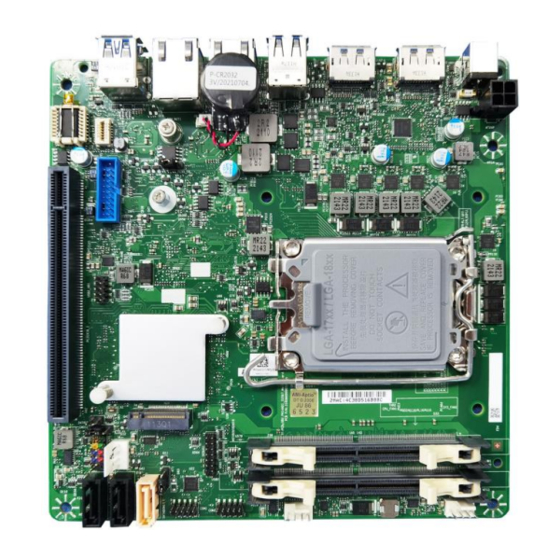
Page 8: Board Image
2.1 Board Image PH14ADI This picture is representative of the latest board revision available at the time of publishing. The board you receive may not look exactly like the above picture. -
Page 9: Block Diagram
2.2 Block Diagram PH14ADI Block Diagram... -
Page 10: Mainboard Mechanical Drawing
2.3 Mainboard Mechanical Drawing... -
Page 11: Board Parts, Jumpers And Connectors
2.4 Board Parts, Jumpers and Connectors This diagram is representative of the latest board revision available at the time of publishing. The board you receive may not look exactly like the above diagram. But for the DIMM number please refer to the above placement for memory installation. For the latest board revision, please visit our web site at https://www.mitacmct.com/. - Page 12 Jumpers & Connectors Connector 1 USB3.2 Gen1 Header (USB3_HR1) 13 SYS_FAN Header (SYS_FAN1) 2 USB2.0 Header (USB2_HR1) 14 ATX Power INPUT (ATX4P) 3 INTRUDER Header (INTRUD1) 15 DC_12V INPUT (DC12IN1) 4 Front IO_PANEL Header 16 Display port_2 (DP_J2) (FIO_PANEL1) 5 SATA Header (SATA2) 17 Display port_1 (DP_J1) 6 SATA POWER Header (SATAPWR1) 18 USB2.0 Rear Port (USB2_J1)
- Page 13 ATX4P: ATX Power Input Header Signal Signal DC12V_IN DC12V_IN SATADOM1: SATA DOM Header Signal SATA1/SATA2: SATA Header Signal M2M: M.2 key-M Header (Slot) Signal Signal 3.3V 3.3V PERN3...
- Page 14 PERP3 PETN3 3.3V PETP3 3.3V 3.3V PERN2 3.3V PERP2 PETN2 PETP2 PERN1 PERP1 PETN1 PETP1 M2_DEVSLP PERN0 / SATA-B+ PERP0 / SATA-B- PETN0 / SATA-A- PETP0 / SATA-A+ M2_PERST# CLKREQ5# PE_CLK_N M2_PE WAKE# PE_CLK_P...
- Page 15 SUSCLK PEDER_OC-PCIE/GND-SATA 3.3V 3.3V 3.3V PCIEX16_1: PCIEX16 Header (Slot) Signal Signal PRSNT1# SMCLK JTAG2 SMDAT JTAG3 JTAG4 JTAG5 JTAG1 V3AUX WAKE# PERST# RSVD_1 REFCLK+ PETp0 REFCLK- PETn0...
- Page 16 PERp0 PRSNT2# PERn0 PETp1 RSVD_4 PETn1 PERp1 PERn1 PETp2 PETn2 PERp2 PERn2 PETp3 PETn3 PERp3 RSVD_2 PERn3 PRSNT2#_2 RSVD_5 PETp4 RSVD_6 PETn4 PERp4 PERn4 PETp5 PETn5 PERp5 PERn5 PETp6...
- Page 17 PETn6 PERp6 PERn6 PETp7 PETn7 PERp7 PRSNT2#_3 PERn7 PETp8 RSVD_7 PETn8 PERp8 PERn8 PETp9 PETn9 PERp9 PERn9 PETp10 PETn10 PERp10 PERn10 PETp11 PETn11 PERp11 PERn11 PETp12 PETn12 PERp12...
- Page 18 PERn12 PETp13 PETn13 PERp13 PERn13 PETp14 PETn14 PERp14 PERn14 PETp15 PETn15 PERp15 PRSNT2#_4 PERn15 RSVD_3 TPM1: TPM Card Header Signal Signal SPI_CLK 3VSB PLTRST_N TPM_DET SPI_MOSI TPM_PIRQ_N SPI_MISO VCC3_TPM SPI_CS2_N SYS_FAN1/CPU_FAN1: System FAN Header, CPU FAN Header Signal FAN TACH FAN Control (PWM)
- Page 19 COM1/COM2: RS-232 COM Port Header Signal Signal DCD (Data Carrier Detect) RXD# (Receive Data) DTR (Data Terminal TXD# (Transmit Data) Ready) DSR (Data Set Ready) RTS (Request To Send) CTS (Clear To Send) RI (Ring Indicator) Key (no pin) DEBUG1: P2398 Card Header Signal Name Signal Name VCC (5V)
- Page 20 SATAPWR1: SATA POWER Header Signal Name VCC(5V) FIO_PANEL1: Front IO Panel Header Signal Description Signal Description Pull-up resistor (510Ω) to [Out] Front panel LED HDD_POWER_LED POWER_LED_MAIN (main color) [Out] Hard disk activity [Out] Front panel LED HDD_LED# POWER_LED_ALT (alt color) GROUND Ground POWER_SWITCH#...
- Page 21 USB2_HR1: Internal USB2.0 Header Signal Signal 5V_USB2_FP 5V_USB2_FP USB2_HR1_1N USB2_HR1_2N USB2_HR1_1P USB2_HR1_2P USB3_HR1: Internal USB3.2 Gen1 Header Signal Signal 5V_USB3_FP USB3P4_RXN 5V_USB3_FP USB3P4_RXP USB3P3_RXP USB3P3_RXP USB3P4_TXN_C USB3P4_TXP_C USB3P3_TXN_C USB3P3_TXP_C USB_PCH_C_DN5 USB_PCH_C_DP5 USB_PCH_C_DN6 USB_PCH_C_DP6 CMOS1: Clear CMOS Header You can reset the CMOS settings by using this jumper. This can be useful if you have forgotten your system/setup password, or need to clear the system BIOS setting.
- Page 22 PEX8_16: PEX8 or PCIEX16 Select Header Signal Name Pull High DFG[5]: PCI Express Bifurcation High: 1 x16 PCI Express* (Default) Low: 2 x8 PCI Express Pull Low Pins 1&2 closed: High: 1 x16 PCI Express* (Default) Pins 2&3 closed: Low: 2 x8 PCI Express...
-
Page 23: Installing The Processor And Heat Sink
Specifications on page 5. Check our website at latest processor support. NOTE: MITAC MITAC is not liable for damage as a result of operating an unsupported configuration. Processor Installation Follow the steps below to install the processors and heat sinks. - Page 24 3. Align and seat the processor package on the socket. Make sure the gold arrow is located in the right direction. 4. Close the load plate. 5. Remove and save the ILM cover. 6. Close the ILM lever and latch.
- Page 25 Processor Uninstallation 1. Open the ILM lever and then the load plate using the finger tab. 2. Place the ILM cover and then carefully remove the processor package. 3. Close the load plate and latch the ILM lever.
- Page 26 Heat sink Installation After installing the processor, you should proceed to install the heat sink. The CPU heat sink will ensure that the processor do not overheat and continue to operate at maximum performance for as long as you own them. The overheated processor is dangerous to the motherboard.
- Page 27 Secure the heat sink screws. Connect the fan cable to complete the installation.
-
Page 28: Thermal Interface Material
2.6 Thermal Interface Material There are two types of thermal interface materials designed for use with the processors. The most common material comes as a small pad attached to the heat sink at the time of purchase. There should be a protective cover over the material. -
Page 29: Tips On Installing Motherboard In Chassis
Some chassis include plastic studs instead of metal. Although the plastic studs are usable, MITAC recommends using metal studs with screws that will fasten the motherboard more securely in place. Below is a chart detailing what the most common motherboard studs look like and... -
Page 31: Installing The Memory
2.8 Installing the Memory Before installing memory, ensure that the memory you have is compatible with the motherboard and processor. Check the MITAC Web site at https://www.mitacmct.com/ for details of the type of memory recommended for your motherboard. Support (1) DIMM slots per channel ... - Page 32 Recommended Memory Population Table Quantity of memory installed Single CPU Installed DIMM1 √ √ DIMM2 √ NOTE: 1. √ indicates a populated DIMM slot. 2. Use paired memory installation for max performance. 3. Populate the same DIMM type in each channel, specifically - Use the same DIMM size - Use the same # of ranks per DIMM...
- Page 33 Memory Installation Procedure Follow these instructions to install memory modules into the PH14ADI. 1. Unlock the clips. 2. Insert the memory module. 3. Lock the clips.
-
Page 34: Attaching Drive Cables
2.9 Attaching Drive Cables Attaching Serial ATA Cables The following illustrates how to make a SATA Cable connection. If you are in need of SATA/SAS cables or power adapters please contact your local sales representative. Attaching SATA Power Cable Attaching SATA Cable... -
Page 35: Installing Add-In Cards
2.10 Installing Add-In Cards Before installing add-in cards, it’s helpful to know if they are fully compatible with your motherboard. For this reason, we’ve provided the diagrams below, showing the slots that may appear on your motherboard. Simply find the appropriate slot for your add-in card and insert the card firmly. Do not force any add-in cards into any slots if they do not seat in place. -
Page 36: Connecting External Devices
2.11 Connecting External Devices Connecting external devices to the motherboard is an easy task. The motherboard supports a number of different interfaces through connecting peripherals. See the following diagrams for the details. Onboard LAN LED Color Definition two (2) onboard Ethernet ports have green Yellow LEDs to indicate LAN... - Page 37 1G RJ45 Connector (LAN1) Diagram Color State Condition LAN link is not established LAN link is Link established Green LAN activity Blinking occurring 10 Mb/s data rate 100 Mb/s data Green Speed rate 1000 Mb/s data Orange rate...
-
Page 38: Installing The Ac/Dc Adaptor
2.12 Installing the AC/DC Adaptor There is one (1) power connector on your PH14ADI motherboard. The PH14ADI supports DC Input 12V/90W DC Adaptor. Please check power adaptor models from MITAC website. 2.13 Finishing Up Congratulations on making it this far! You have finished setting up the hardware aspect of your computer. -
Page 39: Chapter 3: Bios Setup
Chapter 3: BIOS Setup 3.1 About the BIOS The BIOS is the basic input/output system, the firmware on the motherboard that enables your hardware to interface with your software. The BIOS determines what a computer can do without accessing programs from a disk. The BIOS contains all the code required to control the keyboard, display screen, disk drives, serial communications, and a number of miscellaneous functions. - Page 40 Chipset section unless you are absolutely sure of what you are doing. The Chipset defaults have been carefully chosen either by MITAC or your system manufacturer for best performance and reliability. Even a seemingly small change to the Chipset setup options may cause the system to become unstable or unusable.
-
Page 41: Main Menu
3.2 Main Menu In this section, you can alter general features such as the date and time. Note that the options listed below are for options that can directly be changed within the Main Setup screen. BIOS Information It displays BIOS related information. ME FW Version ME Firmware Version. - Page 42 System Date Set the Date. Use Tab to switch between Date elements. Default Ranges: Year: 1998-9999 Months: 1-12 Days: dependent on month. Range of Years may vary. System Time Set the Time. Use Tab to switch between Time elements. hh: 0-23 mm: 0-59 ss: 0-59...
-
Page 43: Advanced Menu
3.3 Advanced Menu This section facilitates configuring advanced BIOS options for your system. Onboard Device Onboard Device Configuration. CPU Configuration CPU Configuration Parameters. VMD Setup Menu VMD Configuration Settings. Trusted Computing Trusted Computing Settings. NCT6126D Super IO Configuration System Super IO Chip Parameters. Hardware Monitor Monitor Hardware Status. - Page 44 S5 RTC Wake Settings Enable system to wake from S5 using RTC alarm. Network Stack Configuration Network Stack Settings. NVMe Configuration NVMe Device Options Settings.
- Page 45 3.3.1 Onboard Device Turbo Mode Enable/Disable processor Turbo Mode (requires Intel Speed Step or Intel Speed Shift to be available and enabled. Disabled / Enabled State After G3 Specify what state to go to when power is re-applied after a power failure (G3 state). S0 State / S5 State DVMT Pre-Allocated Select DVMT 5.0 Pre-Allocated (Fixed) Graphics Memory size used by the Internal...
- Page 46 HD Audio Control Detection of the HD-Audio device. Disabled: HDA will be unconditionally disabled. Enabled: HDA will be unconditionally enabled. Disabled / Enabled Chassis Intrusion Configure Chassis Intrusion. Disabled / Enabled / Reset...
- Page 47 3.3.2 CPU Configuration Displays CPU Signature. Brand String Displays the CPU brand string. VMX Supported or Not. SMX/TXT SMX/TXT Supported or Not.
- Page 48 3.3.3 VMD Setup Menu Enable VMD Controller Enable/Disable to VMD controller. Disabled / Enabled...
- Page 49 3.3.4 Trusted Computing Security Device Support Enables or Disables BIOS support for security device. O.S. will not show Security Device. TCG EFI protocol and INT1A interface will not be available. Disabled / Enabled Pending Operation Schedule an Operation for the ecurity Device. NOTE: Your Computer will reboot during restart in order to change State of Security Device.
- Page 50 3.3.5 NCT6126D Super IO Configuration Serial Port 1 Configuration Set Parameters of Serial Port 1 (COMA). Serial Port 2 Configuration Set Parameters of Serial Port 2 (COMB).
- Page 51 3.3.5.1 Serial Port 1 Configuration Serial Port Enable or Disable Serial Port (COM). Disabled / Enabled Device Settings Device Super IO COM1 Address and IRQ. Read only. Change Settings Select an optimal setting for Super IO Device. Auto / IO=3E8h; IRQ=7; / IO=3E8h, IRQ=3, 4, 5, 6, 7, 9, 10, 11, 12;...
- Page 52 3.3.5.2 Serial Port 2 Configuration Serial Port Enable or Disable Serial Port (COM). Disabled / Enabled Device Settings Device Super IO COM1 Address and IRQ. Read only. Change Settings Select an optimal setting for Super IO Device. Auto / IO=2E8h; IRQ=7; / IO=3E8h, IRQ=3, 4, 5, 6, 7, 9, 10, 11, 12;...
- Page 53 3.3.6 Hardware Monitor Hardware Monitor Alert Enable If Enabled, POST monitors voltage, temperature, and fan status. If these values are out of range, BIOS display warning message and turn on beep sound. Disabled / Enabled System Fan Enable (suppressed if Hardware Monitor Alert is Disabled) If Enabled, POST monitors system fan status.
- Page 54 3.3.7 S5 RTC Wake Settings Wake system from S5 Enable or disable System wake on alarm event. Select Fixed Time, system will wake on the hr:min:sec specified. Disabled / Fixed Time Wake system from S5 (show when Wake system from S5 set to [Fixed time]) Wake up hour Select 0-23.
- Page 55 Wake system from S5 (when set to [Dynamic time]) Wake up minute increase Select 1-5.
- Page 56 3.3.8 Network Stack Configuration Network Stack Enable/Disable UEFI Network Stack. Disabled / Enabled Ipv4 PXE Support (Available when Network Stack Enabled) Enable/Disable Ipv4 PXE Boot Support. If disabled IPV4 PXE boot option will not be created. Disabled / Enabled Ipv6 PXE Support (Available when Network Stack Enabled) Enable/Disable Ipv6 PXE Boot Support.
- Page 57 3.3.9 NVMe Configuration Here shows the Device Name you installed. A sample screenshot shows below. ...
-
Page 58: Security
3.3 Security Administrator Password Set Administrator Password. User Password Set User Password. HDD Security Configuration HDD Security Configuration for selected drive. Secure Boot Secure Boot Configuration. BIOS Update BIOS Update support. - Page 59 3.3.1 HDD Security Configuration Read only.
- Page 60 3.3.2 Secure Boot Secure Boot Secure Boot feature is Active if Secure Boot is Enabled. Platform Key (PK) is enrolled and the System is in User mode. The mode change requires platform reset. Disabled / Enabled Secure Boot Mode Secure Boot mode options: Standard or Custom. In Custom mode, Secure Boot Policy variables can be configured by a physically present user without full authentication.
- Page 61 3.3.2.1 Key Management Factory Key Provision Install factory default Secure Boot keys after the platform reset and while the System is in Setup mode. Disabled / Enabled Restore Factory Keys Force System to User Mode. Install factory default Secure Boot key databases. Reset to Setup Mode Deleting all Secure Boot key databases from NVRAM.
- Page 62 Key Exchange Keys Enroll Factory Defaults or load certificates from a file: 1. Public Key Certificate: a) EFI_SIGNATURE_LIST b) EFI_CERT_X509 (DER) c) EFI_CERT_RSA2048 (bin) d) EFI_CERT_SHAXXX 2. Authenticated UEFI Variable 3. EFI PE/COFF Image (SHA256) Key source: Factory, External, Mixed Authorized Signatures Enroll Factory Defaults or load certificates from a file: 1.
- Page 63 OsRecovery Signatures Enroll Factory Defaults or load certificates from a file: 1. Public Key Certificate: a) EFI_SIGNATURE_LIST b) EFI_CERT_X509 (DER) c) EFI_CERT_RSA2048 (bin) d) EFI_CERT_SHAXXX 2. Authenticated UEFI Variable 3. EFI PE/COFF Image (SHA256) Key Source: Factory, External, Mixed Export Secure Boot variables Copy NVRAM content of Secure Boot variables to files in a root folder on a file system device.
- Page 64 3.3.3 BIOS Update Path for ROM Image Enter the path to the BIOS update option.
-
Page 65: Boot
3.4 Boot Setup Prompt Timeout Number of seconds to wait for setup activation key. 65535 (0xFFFF) means indefinite waiting. Bootup NumLock State Select the keyboard NumLock state. On / Off Boot Option #1 ~ Boot Option #8 Sets the system boot order. Device Name / Disabled UEFI Hard Disk Drive BBS Priorities Specifies the Boot Device Priority sequence from available Hard Disk Drives. - Page 66 3.4.1 Drive BBS Priorities Boot Option #1 Sets the system boot order. Boot Device Name #1 of this type / Disabled...
-
Page 67: Save & Exit
3.5 Save & Exit Save Changes and Exit Reset the system after saving the changes. Discard Changes and Exit Reset system setup without saving any changes. Restore Defaults Restore/Load Default values for all the setup options. -
Page 68: Event Logs
3.6 Event Logs Change Smbios Event Log Settings Press <Enter> to change the Smbios Event Log configuration. View Smbios Event Log Press <Enter> to view the Smbios Event Log records. - Page 69 3.6.1 Change Smbios Event Log Settings Smbios Event Log Change this to enable or disable all feature of Smbios Event Logging during boot. Disabled / Enabled...
- Page 70 Erase Event Log Choose options for erasing Smbios Event Log. Erasing is done prior to any logging activation during reset. No / Yes, next reset / Yes, every reset When Log is Full Choose options for reactions to a full Smbios Event Log. Do Nothing / Erase Immediately...
- Page 71 3.6.2 View Smbios Event Log DATE / TIME / ERROR CODE / SEVERITY / COUNT Description: Log Area Reset and Count is applicable only for Multi-Events. By Events. MM/DD/YY HH:MM:SS Smbios 0x16 N/A N/A...
-
Page 72: Chapter 4: Diagnostics
BIOS flash failure, you must contact your dealer for a replacement BIOS. There are no exceptions. MITAC does not have a policy for replacing BIOS chips directly with end users. In no event will MITAC be held responsible for damages done by the end user. -
Page 73: Amibios Post Code (Aptio)
4.2 AMIBIOS Post Code (Aptio) The POST code checkpoints are the largest set of checkpoints during the BIOS pre- boot process. The following table describes the type of checkpoints that may occur during the POST portion of the BIOS: Checkpoint Ranges Status Code Range Description 0x01 –... - Page 74 SEC Error Codes 0x0C – 0x0D Reserved for future AMI SEC error codes 0x0E Microcode not found 0x0F Microcode not found SEC Beep Codes None PEI Phase Status Code Description Progress Codes 0x10 PEI Core is started 0x11 Pre-memory CPU initialization is started 0x12 Pre-memory CPU initialization (CPU module specific) 0x13...
- Page 75 Status Code Description 0x38 Post-Memory North Bridge initialization (North Bridge module specific) 0x39 Post-Memory North Bridge initialization (North Bridge module specific) 0x3A Post-Memory North Bridge initialization (North Bridge module specific) 0x3B Post-Memory South Bridge initialization is started 0x3C Post-Memory South Bridge initialization (South Bridge module specific) 0x3D Post-Memory South Bridge initialization (South Bridge module specific) 0x3E...
- Page 76 Recovery Progress Codes 0xF0 Recovery condition triggered by firmware (Auto recovery) 0xF1 Recovery condition triggered by user (Forced recovery) 0xF2 Recovery process started 0xF3 Recovery firmware image is found 0xF4 Recovery firmware image is loaded 0xF5 – 0xF7 Reserved for future AMI progress codes Recovery Error Codes 0xF8 Recovery PPI is not available...
- Page 77 Status Code Description 0x6C North Bridge DXE initialization (North Bridge module specific) 0x6D North Bridge DXE initialization (North Bridge module specific) 0x6E North Bridge DXE initialization (North Bridge module specific) 0x6F North Bridge DXE initialization (North Bridge module specific) 0x70 South Bridge DXE initialization is started 0x71 South Bridge DXE SMM initialization is started...
- Page 78 Status Code Description 0xA5 SCSI Reset 0xA6 SCSI Detect 0xA7 SCSI Enable 0xA8 Setup Verifying Password 0xA9 Start of Setup 0xAA Reserved for ASL (see ASL Status Codes section below) 0xAB Setup Input Wait 0xAC Reserved for ASL (see ASL Status Codes section below) 0xAD Ready To Boot event 0xAE...
- Page 79 DXE Beep Codes # of Beeps Description Invalid password Some of the Architectural Protocols are not available No Console Output Devices are found No Console Input Devices are found Flash update is failed Reset protocol is not available Platform PCI resource requirements cannot be met ACPI/ASL Checkpoints Status Code Description...
-
Page 80: Appendix I: How To Recover Uefi Bios
The BIOS Recovery file is named xxxx.cap, where the 'xxxx' portion is the motherboard model number. Examples: 5630.cap, 7106.cap, 7109.cap, etc. Please make sure that you are using the correct BIOS Recovery file from MiTAC's web site. BIOS Recovery Process Place the recovery BIOS file (xxxx.cap) in the root directory of a USB disk. - Page 81 “Flash update completed. Press any key to reset the system” displayed on screen. Remove the USB disk and reboot. If your system does not have video output or the POST code halts at “FF” on the right-lower portion of the screen, please contact MiTAC representatives for RMA service.
-
Page 82: Appendix Ii: Fan And Temp Sensors
Appendix II: Fan and Temp Sensors This section aims to help readers identify the locations of some specific FAN and Temp Sensors on the motherboard. A table of BIOS Temp sensor name explanation is also included for readers’ reference. Figure 1: Sensor Location NOTE: The red mark indicates the sensor. - Page 83 BIOS Temp Sensor Name Explanation: BIOS Temp Sensor Name Explanation CPU Temperature Temperature of the CPU Area CPU VR Temperature Temperature of the CPU VR Area DIMM Temperature Temperature of DIMM Slot CPU Fan Speed Fan Speed of CPU_FAN1 System Fan Speed Fan Speed of System_FAN1...
Need help?
Do you have a question about the PH14ADI and is the answer not in the manual?
Questions and answers