Table of Contents
Advertisement
Quick Links
S8016
Version 1.0b
Copyright
Copyright © 2023 MiTAC International Corporation. All rights reserved. No part of
this manual may be reproduced or translated without prior written consent from
MiTAC International Corporation.
Trademark
All registered and unregistered trademarks and company names contained in this
manual are property of their respective owners including, but not limited to the
following.
®
TYAN
is a trademark of MiTAC International Corporation.
®
®
AMD
is a trademark of AMD
Corporation.
AMI, AMI BIOS are trademarks of AMI Technologies.
®
®
Microsoft
, Windows
are trademarks of Microsoft Corporation.
®
Winbond
is a trademark of Winbond Electronics Corporation.
Notice
Information contained in this document is furnished by MiTAC International
Corporation and has been reviewed for accuracy and reliability prior to printing.
MiTAC assumes no liability whatsoever, and disclaims any express or implied
®
warranty, relating to sale and/or use of TYAN
products including liability or
warranties relating to fitness for a particular purpose or merchantability. MiTAC
retains the right to make changes to product descriptions and/or specifications at
any time, without notice. In no event will MiTAC be held liable for any direct or
indirect, incidental or consequential damage, loss of use, loss of data or other
malady resulting from errors or inaccuracies of information contained in this
document.
1
http://www.tyan.com
Advertisement
Table of Contents

Related Manuals for MiTAC TYAN S8016


Summary of Contents for MiTAC TYAN S8016
- Page 1 In no event will MiTAC be held liable for any direct or indirect, incidental or consequential damage, loss of use, loss of data or other malady resulting from errors or inaccuracies of information contained in this document.
-
Page 2: Table Of Contents
Contents Before you begin… ..................3 Chapter 1: Instruction ................5 1.1 Congratulations ................. 5 1.2 Hardware Specifications ..............5 1.3 Software Specifications ..............7 Chapter 2: Board Installation ..............9 2.1 Board Image ..................10 2.2 Block Diagram ................. 11 2.3 Motherboard Mechanical Drawing ........... -
Page 3: Before You Begin
Before you begin… Check the box contents! The retail motherboard package should contain the following: S8016 Motherboard x 1 SATA Cable x 2 M.2 Latch x 1 Rear IO shielding x 1 1 x S8016 Quick Installation Guide IMPORTANT NOTE: Sales samples may not come with any of the accessories listed above. - Page 4 NOTE http://www.tyan.com...
-
Page 5: Chapter 1: Instruction
Chapter 1: Instruction 1.1 Congratulations ® ® You have purchased the powerful TYAN S8016 motherboard, based on the AMD ® B650 FCH chipset. The S8016 is designed to support single Ryzen™ 7000 Series Processor, and up to 128GB UDIMM / DDR5 ECC UDIMM & non-ECC 4800 ®... - Page 6 Connector type (1) VGA Graphic VGA Resolution Up to 1920x1200 Chipset Aspeed AST2600 Connector type (2) Display ports 1.2 Graphic Display Resolution Up to 4096X2304 @60Hz Port Chipset AMD AM5 Ryzen processor (4) Stacked USB 3.2 Gen1 port (@rear) / (1) USB 3.2 Gen1 TYPE A/ (1) USB 3.2 Gen1 header (1) VGA port...
-
Page 7: Software Specifications
Environment Non-operating Temp. - 40° C ~ 70° C (-40° F ~ 158° F) In/Non-operating 90%, non-condensing at 35° C Humidity RoHS RoHS 6/6 Compliant Operating OS supported list Please refer to our AVL support lists. System Motherboard (1) S8016 Motherboard Manual (1) Quick Installation Guide Package... - Page 8 NOTE http://www.tyan.com...
-
Page 9: Chapter 2: Board Installation
Unplug the power from your computer power supply and then touch a safely grounded object to release static charge (i.e. power supply case). For the safest conditions, MiTAC recommends wearing a static safety wrist strap. (2) Hold the motherboard by its edges and do not touch the bottom of the board, or flex the board in any way. -
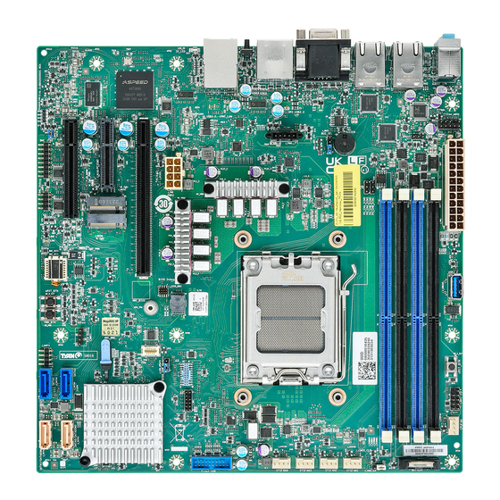
Page 10: Board Image
2.1 Board Image S8016AGM2NR This picture is representative of the latest board revision available at the time of publishing. The board you receive may not look exactly like the above picture. http://www.tyan.com... -
Page 11: Block Diagram
2.2 Block Diagram S8016 Block Diagram http://www.tyan.com... -
Page 12: Motherboard Mechanical Drawing
2.3 Motherboard Mechanical Drawing http://www.tyan.com... -
Page 13: Board Parts, Jumpers And Connectors
2.4 Board Parts, Jumpers and Connectors This diagram is representative of the latest board revision available at the time of publishing. The board you receive may not look exactly like the above diagram. The DIMM slot numbers shown above can be used as a reference when reviewing the DIMM population guidelines shown later in the manual. - Page 14 Jumpers & Connectors Connectors 1. 8-pin, CPU and CPU MEM Power Connector 10. 24-pin ATX Power Connector (12V input) (J_PW2) (J_PW1) 2. M.2 Connector (J_M2CN2) 11. 3 port audio jack (J_F8) 3. M.2 Connector (J_C2CN1) 12. RJ45 (J_F6) 4. TPM Connector (J_TPM1) 13.
- Page 15 J_CPUFAN1/J_SYSFAN1/J_SYSFAN2/J_SYSFAN3/J_SYSFAN4: CPU/System Fan Connector Signal P12V TACHOMETER Use this header to connect the cooling fan to your motherboard to keep the system stable and reliable. J2: HDT Header Signal Signal P1V8_HDT HDT_HDR_AM5_TEST17 APU_TCK HDT_HDR_RST_N HDT_HDR_AM5_TEST16 APU_TMS HDT_HDR_DBRDY HDT_CPU_DBRDY1 HDT_HDR_TDI HDT_HDR_DBREQ_N APU_TD0 HDT_HDR_PLLTEST0 HDT_TRST_N...
- Page 16 J_TPM1: TPM Header Signal Signal SPI_TPM_CONN_CLK P3V3_AUX FM_TPM_CONN_PR RST_TPM_CONN_N SNT_R_N IRQ_TPM_CONN_PI SPI_TPM_CONN_MOSI RQ_N SPI_TPM_CONN_MISO P3V3_AUX SPI_TPM_CONN_CS_N NC_TPM_PIN6 J_DB1: Port80 DEBUG Header Signal Signal P3V3_VCC_DB DBG_ESPI_CS0_N DBG_ESPI_IO_0 DBG_ESPI_IO_1 DBG_ESPI_RST_N DBG_ESPI_IO_2 DBG_ESPI_IO_3 DBG_ESPI_CLK DBG_ESPI_ALRT1_N J4: BMC AST2600 DEBUG Header Signal Signal P3V3_AUX_ASD_D TP_RST_JTAG JTAG_ASD_TDO_CONN JTAG_ASD_TMS_CONN...
- Page 17 J_SATA1/J_SATA2: SATA DOM Connector Signal SATA_PT21_TX_C_DP0 SATA_PT21_TX_C_DN0 SATA_PT21_RX_C_DN0 SATA_PT21_RX_C_DP0 SATADOM1_P7_VCC SATADOM1_MT1_GND SATADOM1_MT2_VCC J_SATA3/J_SATA4: SATA Connector Signal SATA_PT21_TX_C_DP2 SATA_PT21_TX_C_DN2 SATA_PT21_RX_C_DN2 SATA_PT21_RX_C_DP2 J_HDAUD1: AUDIO Header Signal Signal MIC2-L_R AGND_C_5 MIC2-R_R FP_AUD_DETECT_R_N LINE2-R_R MIC2-JD FIO_SENSE LINE2-L_R LINE2-JD http://www.tyan.com...
- Page 18 J_HDFP1: Front Panel Header Signal Signal P5V_LED_A GRN_BLNK_HR LED_HDD_ACT_N YLW_BLNK_HR FP_PWR_BTN_R_N FP_RST_BTN_R_N J_USB1: Front Panel USB Header Signal Signal P5V_USB3_HD1 USB2_PT21_P2_CMC_P1 USB3_PT21_P2_RX_CMC_N0 USB2_PT21_P2_CMC_N1 USB3_PT21_P2_RX_CMS_P0 USB3_PT21_P2_TX_CMC_P1 USB3_PT21_P2_TX_CMC_N0 USB3_PT21_P2_TX_CMC_N1 USB3_PT21_P2_TX_CMC_P0 USB3_PT21_P2_RX_CMC_P1 USB2_PT21_P2_CMC_N0 USB3_PT21_P2_RX_CMC_N1 USB2_PT21_P2_CMC_P0 P5V_USB3_HD2 USB3_HD_OC_N J_CHAS: Chassis Intrusion Header Signal Signal BMC_INTRUDER_HDR_N High: Normal Low: Case Open...
- Page 19 J1: Audio SPDIF OUT Header Signal S/PDIF-OUT1_R P5V_USB_AUX_SPDIFOUT J_CMOS_CLR: Clear CMOS Jumper Signal Signal VBAT VDDBT_RTC_R (Default) Pin1-2 closed: Normal Mode Pin2-3 closed: Clear CMOS J_USB_UPDATE: BIOS Update by USB Header Signal Signal NC_USB_BIOS_UPDATE USB_BIOS_UPDATE_R EN_USB_BIOS_UPDATE (Default) Pin1-2 closed: Normal Mode Pin2-3 closed: Enable BIOS USB Update http://www.tyan.com...
- Page 20 J_BUZ1: Buzzer Mode Select Header SPKR_BUZZ_IN SPKR_BUZZ (Default) Pin3-4 closed: Normal Mode Pin2-3 closed: Disable PC Beep Pin1-4 closed: Use the external speaker http://www.tyan.com...
- Page 21 J_PCIE6: PCIE SLOT / Gen5 Physical x16 Connector Signal Signal P12V_CPU P12V_CPU P12V_CPU P12V_CPU P12V_CPU PD_SLOT6_JTAG2 SMB_SLOT6_SCL PU_SLOT6_JTAG3 SMB_SLOT6_SDA PU_SLOT6_JTAG4 PU_SLOT6_JTAG5 P3V3 P3V3 PD_SLOT6_JTAG1 P3V3 P3V3_AUX RST_SLOT6_PERST_N IRQ_LVC3_SLOT6_WAKE_N CLKREQ_SLOT6_Q_N CLK_100M_SLOT6_DP CLK_100M_SLOT6_DN P5E_AM5_SLOT6_TX_C_DP<0> P5E_AM5_SLOT6_TX_C_DN<0> P5E_AM5_SLOT6_RX_DP<0> RST_PCIE6_PRSNT_N_0 P5E_AM5_SLOT6_RX_DN<0> PD_SLOT6_A19_RSVD_HFF P5E_AM5_SLOT6_TX_C_DP<1> P5E_AM5_SLOT6_TX_C_DN<1> P5E_AM5_SLOT6_RX_DP<1> P5E_AM5_SLOT6_RX_DN<1>...
- Page 22 P5E_AM5_SLOT6_TX_C_DN<2> P5E_AM5_SLOT6_RX_DP<2> P5E_AM5_SLOT6_RX_DN<2> P5E_AM5_SLOT6_TX_C_DP<3> P5E_AM5_SLOT6_TX_C_DN<3> P5E_AM5_SLOT6_RX_DP<3> P5E_AM5_SLOT6_RX_DN<3> TP_FM_SYS_PWRBRK_R2_N RST_PCIE6_PRSNT_N_1 PD_SLOT6_A32_RSVD_HFF PD_SLOT6_A33_RSVD_HFF P5E_AM5_SLOT6_TX_C_DP<4> P5E_AM5_SLOT6_TX_C_DN<4> P5E_AM5_SLOT6_RX_DP<4> P5E_AM5_SLOT6_RX_DN<4> P5E_AM5_SLOT6_TX_C_DP<5> P5E_AM5_SLOT6_TX_C_DN<5> P5E_AM5_SLOT6_RX_DP<5> P5E_AM5_SLOT6_RX_DN<5> P5E_AM5_SLOT6_TX_C_DP<6> P5E_AM5_SLOT6_TX_C_DN<6> P5E_AM5_SLOT6_RX_DP<6> P5E_AM5_SLOT6_RX_DN<6> P5E_AM5_SLOT6_TX_C_DP<7> P5E_AM5_SLOT6_TX_C_DN<7> P5E_AM5_SLOT6_RX_DP<7> P5E_AM5_SLOT6_RX_DN<7> RST_PCIE6_PRSNT_N_2 PD_SLOT6_A50_RSVD_HFF P5E_AM5_SLOT6_TX_C_DP<8> P5E_AM5_SLOT6_TX_C_DN<8> P5E_AM5_SLOT6_RX_DP<8> P5E_AM5_SLOT6_RX_DN<8> P5E_AM5_SLOT6_TX_C_DP<9> P5E_AM5_SLOT6_TX_C_DN<9> P5E_AM5_SLOT6_RX_DP<9> P5E_AM5_SLOT6_RX_DN<9> P5E_AM5_SLOT6_TX_C_DP<10> P5E_AM5_SLOT6_TX_C_DN<10> P5E_AM5_SLOT6_RX_DP<10> P5E_AM5_SLOT6_RX_DN<10>...
- Page 23 P5E_AM5_SLOT6_TX_C_DP<13> P5E_AM5_SLOT6_TX_C_DN<13> P5E_AM5_SLOT6_RX_DP<13> P5E_AM5_SLOT6_RX_DN<13> P5E_AM5_SLOT6_TX_C_DP<14> P5E_AM5_SLOT6_TX_C_DN<14> P5E_AM5_SLOT6_RX_DP<14> P5E_AM5_SLOT6_RX_DN<14> P5E_AM5_SLOT6_TX_C_DP<15> P5E_AM5_SLOT6_TX_C_DN<15> P5E_AM5_SLOT6_RX_DP<15> P5E_AM5_SLOT6_RX_DN<15> RST_PCIE6_PRSNT_N_3 PD_SLOT6_B82_RSVD_HFF J_PCIE4: PCIE SLOT / Gen4 Physical x8Connector Signal Signal P12V_CPU P12V_CPU P12V_CPU P12V_CPU P12V_CPU PD_SLOT4_JTAG2 SMB_SLOT4_SCL PU_SLOT4_JTAG3 SMB_SLOT4_SDA PU_SLOT4_JTAG4 http://www.tyan.com...
- Page 24 PU_SLOT4_JTAG5 P3V3 P3V3 PD_SLOT4_JTAG1 P3V3 P3V3_AUX RST_SLOT4_PERST_N IRQ_LVC3_SLOT4_WAKE_N CLKREQ_SLOT4_Q_N CLK_100M_SLOT4_DP CLK_100M_SLOT4_DN P4E_PT21_SLOT4_TX_C_DP<0> P4E_PT21_SLOT4_TX_C_DN<0> P4E_PT21_SLOT4_RX_DP<0> RST_PCIE4_PRSNT_N_0 P4E_PT21_SLOT4_RX_DN<0> PD_SLOT4_A19_RSVD_HFF P4E_PT21_SLOT4_TX_C_DP<1> P4E_PT21_SLOT4_TX_C_DN<1> P4E_PT21_SLOT4_RX_DP<1> P4E_PT21_SLOT4_RX_DN<1> P4E_PT21_SLOT4_TX_C_DP<2> P4E_PT21_SLOT4_TX_C_DN<2> P4E_PT21_SLOT4_RX_DP<2> P4E_PT21_SLOT4_RX_DN<2> P4E_PT21_SLOT4_TX_C_DP<3> P4E_PT21_SLOT4_TX_C_DN<3> P4E_PT21_SLOT4_RX_DP<3> P4E_PT21_SLOT4_RX_DN<3> TP_FM_SYS_PWRBRK_R1_N RST_PCIE4_PRSNT_N_1 PD_SLOT4_A32_RSVD_HFF PD_SLOT4_A33_RSVD_HFF RST_PCIE4_PRSNT_N_2 http://www.tyan.com...
- Page 25 J_PCIE5: PCIE SLOT / Gen4 Physical x4 Connector Signal Signal P12V_CPU P12V_CPU P12V_CPU P12V_CPU P12V_CPU PD_SLOT5_JTAG2 SMB_SLOT5_SCL PU_SLOT5_JTAG3 SMB_SLOT5_SDA PU_SLOT5_JTAG4 PU_SLOT5_JTAG5 P3V3 P3V3 PD_SLOT5_JTAG1 P3V3 P3V3_AUX RST_SLOT5_PERST_N IRQ_LVC3_SLOT5_WAKE_N CLKREQ_SLOT5_Q_N CLK_100M_SLOT5_DP CLK_100M_SLOT5_DN P4E_AM5_SLOT5_TX_C_DP<0> P4E_AM5_SLOT5_TX_C_DN<0> P4E_AM5_SLOT5_RX_DP<0> RST_PCIE5_PRSNT_N_0 P4E_AM5_SLOT5_RX_DN<0> PD_SLOT5_A19_RSVD_HFF P4E_AM5_SLOT5_TX_C_DP<1> P4E_AM5_SLOT5_TX_C_DN<1> P4E_AM5_SLOT5_RX_DP<1> P4E_AM5_SLOT5_RX_DN<1>...
- Page 26 P4E_AM5_SLOT5_TX_C_DP<2> P4E_AM5_SLOT5_TX_C_DN<2> P4E_AM5_SLOT5_RX_DP<2> P4E_AM5_SLOT5_RX_DN<2> P4E_AM5_SLOT5_TX_C_DP<3> P4E_AM5_SLOT5_TX_C_DN<3> P4E_AM5_SLOT5_RX_DP<3> P4E_AM5_SLOT5_RX_DN<3> TP_FM_SYS_PWRBRK_R3_N RST_PCIE5_PRSNT_N_1 PD_SLOT5_A32_RSVD_HFF J_M2CN1: M.2 SLOT/Gen4 x2 M.2 2280 Connector Signal Signal P3V3_M2_1 P3V3_M2_1 NC_NGFF1_6 PU_NGFF1_PLN_N M2_1_SLOT_LED_N P3V3_M2_1 P3V3_M2_1 P3V3_M2_1 P3V3_M2_1 http://www.tyan.com...
- Page 27 NC_NGFF1_20 P1V8_AUX NC_NGFF1_24 FM_NGSFF1_N NC_NGFF1_28 P4E_PT21_M2SLOT1_RX_R_DN1 PU_NGFF1_PLA_S3_N P4E_PT21_M2SLOT1_RX_R_DP1 USB2_M2_1_DP P4E_PT21_M2SLOT1_TX_C_DN1 USB2_M2_1_DN P4E_PT21_M2SLOT1_TX_C_DP1 SMB_M2_1_SCL P4E_PT21_M2SLOT1_RX_R_DN0 SMB_M2_1_SDA P4E_PT21_M2SLOT1_RX_R_DP0 IRQ_SMB_M2_1_ALT_LV18_N NC_NGFF1_46 P4E_PT21_M2SLOT1_TX_C_DN0 NC_NGFF1_48 P4E_PT21_M2SLOT1_TX_C_DP0 M2_1_PERST_N M2_1_CLKREQ_N CLK_100M_M2SLOT1_DN M2_1_PEWAKE_N CLK_100M_M2SLOT2_DP NC_NGFF1_56 NC_NGFF1_58 M KEY M KEY M KEY M KEY M KEY M KEY M KEY M KEY NC_NGFF1_67...
- Page 28 J_M2CN2: M.2 SLOT/Gen4 x2 M.2 2280 Connector Signal Signal P3V3_M2_2 P3V3_M2_2 NC_NGFF2_6 PU_NGFF2_PLN_N M2_2_SLOT_LED_N P3V3_M2_2 P3V3_M2_2 P3V3_M2_2 P3V3_M2_2 NC_NGFF2_20 P1V8_AUX NC_NGFF2_24 FM_NGSFF2_N NC_NGFF2_28 P4E_AM5_M2SLOT2_RX_R_DN1 PU_NGFF2_PLA_S3_N P4E_AM5_M2SLOT2_RX_R_DP1 USB2_M2_2_DP P4E_AM5_M2SLOT2_TX_C_DN1 USB2_M2_2_DN P4E_AM5_M2SLOT2_TX_C_DP1 SMB_M2_2_SCL http://www.tyan.com...
- Page 29 P4E_AM5_M2SLOT2_RX_R_DN0 SMB_M2_2_SDA P4E_AM5_M2SLOT2_RX_R_DP0 IRQ_SMB_M2_2_ALT_LV18_N NC_NGFF2_46 P4E_AM5_M2SLOT2_TX_C_DN0 NC_NGFF2_48 P4E_AM5_M2SLOT2_TX_C_DP0 M2_2_PERST_N M2_2_CLKREQ_N CLK_100M_M2SLOT2_DN M2_2_PEWAKE_N CLK_100M_M2SLOT2_DP NC_NGFF2_56 NC_NGFF2_58 M KEY M KEY M KEY M KEY M KEY M KEY M KEY M KEY NC_NGFF2_67 NC_NGFF2_68 FM_M2_2_PEDET_N P3V3_M2_2 P3V3_M2_2 P3V3_M2_2 http://www.tyan.com...
-
Page 30: Led Definitions
2.5 LED Definitions http://www.tyan.com... - Page 31 Signal P3V3_STBY State Description The LED shuts off when the LED_BMCHB Heart Beat BMC controller cannot be detected or properly initiated. The LED blinks per second to Blinking Green indicate that the BMC controller is working normally Signal P3V3_AUX LED_ID ID LED State Description...
-
Page 32: Installing The Processor And Heatsink
AMD processors for this specific motherboard. NOTE: MiTAC is not liable for damage as a result of operating an unsupported configuration. Processor Installation (Socket LGA1718, AMD AM5 Ryzen series (Raphael) Follow the steps below to install the processors and heat sinks. - Page 33 3. Align and seat the processor package on the socket. Make sure the gold arrow is located in the right direction. 4. Close the load plate. 5. Remove and save the ILM cover. 6. Close the ILM lever and latch. http://www.tyan.com...
- Page 34 Heat sink Installation After installing the processor, you will need to proceed to install the heat sink. The CPU heat sink will ensure that the processor do not overheat and continue to operate at maximum performance for as long as you own them. An overheated processor is dangerous to the motherboard.
- Page 35 3. Secure the heatsink screws. 4. Connect the heatsink fan cable. http://www.tyan.com...
-
Page 36: Thermal Interface Material
2.7 Thermal Interface Material There are two types of thermal interface materials designed for use with the processors. The most common material comes as a small pad attached to the heat sink at the time of purchase. There should be a protective cover over the material. -
Page 37: Tips On Installing Motherboard In Chassis
2.8 Tips on Installing Motherboard in Chassis Before installing your motherboard, make sure your chassis has the necessary motherboard support studs installed. These studs are usually metal and are gold in color. Usually, the chassis manufacturer will pre-install the support studs. If you are unsure of stud placement, simply lay the motherboard inside the chassis and align the screw holes of the motherboard to the studs inside the case. - Page 38 Some chassis include plastic studs instead of metal. Although the plastic studs are usable, MiTAC recommends using metal studs with screws that will fasten the motherboard more securely in place. Below is a chart detailing what the most common motherboard studs look like and how they should be installed.
-
Page 39: Installing The Memory
2.9 Installing the Memory Before installing memory, ensure that the memory you have is compatible with the motherboard and processor. Check the TYAN Web site at http://www.tyan.com details of the type of memory recommended for your motherboard. Memory Population Rules: 1 DIMM: DIMM1 first (B) 2 DIMM: DIMM A1 and DIMM B1 4 DIMM: DIMM A1, A0, DIMM B1, B0... - Page 40 http://www.tyan.com...
- Page 41 Memory Installation Procedure Follow these instructions to install memory modules into the S8016. 1. Unlock the clips. 2. Insert the memory module. 3. Lock the clips. http://www.tyan.com...
-
Page 42: Installing Add-In Cards
2.10 Installing Add-In Cards Before installing add-in cards, it’s helpful to know if they are fully compatible with your motherboard. For this reason, we’ve provided the diagrams below, showing the slots that may appear on your motherboard. Simply find the appropriate slot for your add-in card and insert the card firmly. Do not force any add-in cards into any slots if they do not seat in place. -
Page 43: Connecting External Devices
2.11 Connecting External Devices Connecting external devices to the motherboard is an easy task. The motherboard supports a number of different interfaces through connecting peripherals. See the following diagrams for the details. Onboard LAN LED Color Definition three (3) onboard Ethernet ports have green and Amber LEDs to indicate LAN status. -
Page 44: Installing The Power Supply
2.12 Installing the Power Supply There are two (2) power connectors on your S8016 motherboard. The S8016 supports EPS 12V power supply. J_PW1: ATX 24-pin Main Power Connector Signal Signal +3.3V_1 +3.3V_4 +3.3V_2 -12V COM_1 COM_4 +5V_1 PS-ON# COM_2 COM_5 +5V_2 COM_6 COM_3... -
Page 45: Finishing Up
2.13 Finishing Up Congratulations on making it this far! You have finished setting up the hardware aspect of your computer. Before closing up your chassis, make sure that all cables and wires are connected properly, especially SATA cables and most importantly, jumpers. - Page 46 NOTE http://www.tyan.com...
-
Page 47: Chapter 3: Bios Setup
Chapter 3: BIOS Setup 3.1 About the BIOS The BIOS is the basic input/output system, the firmware on the motherboard that enables your hardware to interface with your software. The BIOS determines what a computer can do without accessing programs from a disk. The BIOS contains all the code required to control the keyboard, display screen, disk drives, serial communications, and a number of miscellaneous functions. - Page 48 Chipset section unless you are absolutely sure of what you are doing. The Chipset defaults have been carefully chosen either by MiTAC or your system manufacturer for best performance and reliability. Even a seemingly small change to the Chipset setup options may cause the system to become unstable or unusable.
-
Page 49: Main Menu
3.2 Main Menu In this section, you can alter general features such as the date and time. Note that the options listed below are for options that can directly be changed within the Main Setup screen. BIOS Information It displays product name, BIOS version and build date and time. Memory Information It displays the total memory size and memory frequency. -
Page 50: Advanced Menu
3.3 Advanced Menu This section facilitates configuring advanced BIOS options for your system. NOTE: This is a sample screenshot of the Advanced Menu. The HII network drivers displayed here depend on the card(s) you installed and the functions you enabled. Network Stack Configuration Network Stack Settings S5 RTC Wake Settings... - Page 51 Hardware Health Configuration Hardware Health Configuration PCI Subsystem Settings PCI, PCI-X and PCI Express Settings NVMe Configuration NVMe Device Information Trusted Computing Trusted Computing settings Super IO Configuration System Super IO Chip Parameters CSM Configuration CSM Configuration, Enable/Disable Option ROM execution setting, etc AMD fTPM Configuration AMD fTPM Settings T1s Auth Configuration...
- Page 52 MAC:xxxxxxxxxxxx-IPv6 Network Configuration Configure IPv6 network parameters. (MAC: xxxxxxxxxxxx) http://www.tyan.com...
- Page 53 3.3.1 Network Stack Configuration Network Stack Enable/Disable UEFI Network Stack Disabled / Enabled NOTE: When Network Stack was set to [Enabled], the following item will appear. IPv4 PXE Support Enable/Disable IPv4 PXE boot support. If disabled, IPv4 PXE boot support will not be available.
- Page 54 IPv6 HTTPs Support Enable/Disable IPv6 HTTPs boot support. If disabled, IPv6 HTTPS boot support will not be available. Disabled / Enabled PXE boot wait time Wait time in seconds to press ESC key to abort the PXE boot. Use either +/- or numeric keys to set the value.
- Page 55 3.3.2 S5 RTC Wake Settings Wake system from S5 Enable or disable System wake on alarm event. Select FixedTime, system will wake on the hr::min::sec specified. Select DynamicTime, system will wake on the current time + Increase minute(s). Disabled / Fixed Time / Dynamic Time When Wake system from S5 is set to [Fixed Time] Wake up hour Select 0-23.
- Page 56 3.3.3 Serial Port Console Redirection COM1 Console Redirection Console redirection enable or disable. Disabled / Enabled Legacy Console Redirection Legacy Console Redirection Settings Serial Port for Out-Of-Band Management/Windows Emergency Services (EMS) Console Redirection Console redirection enable or disable. Disabled / Enabled Console Redirection Settings The settings specify how the host computer (which the user is using) will exchange data.
- Page 57 3.3.3.1 COM1 Console Redirection Settings Terminal Type Emulation: ANSI: Extended ASCII char set. VT100: ASCII char set. VT100+: Extends VT100 to support color function keys, etc. VT-UTF8: Uses UTF8 encoding to map Unicode chars onto 1 or more bytes. VT-UTF8 / VT100 / VT100+ / ANSI Bits per Second Select serial port transmission speed.
- Page 58 Stop Bits Stop bits indicate the end of a serial data packet. (A start bit indicates the beginning). The standard setting is 1 stop bit. Communication with slow devices may require more than 1 stop bit. 1 / 2 Flow Control Flow Control can prevent data loss from buffer overflow.
- Page 59 3.3.3.2 Legacy Console Redirection Settings Redirection COM Port Select a COM port to display redirection of Legacy OS and Legacy OPROM Messages. COM1 Resolution On Legacy OS, the Number of Rows and Columns supported redirection. 80x24 / 80x25 Redirect After POST when Bootloader is selected, then Legacy Console Redirection is disabled before booting to legacy OS, when Always Enable is selected, then Legacy Console Redirection is enabled for Legacy OS.
- Page 60 3.3.3.3 Serial Port for Out-Of-Band Management/Windows Emergency Services (EMS) Console Redirection Settings Out-of Band Mgmt Port Microsoft Windows Emergency Management Services (EMS) allows for remote management of a Windows Server OS through a serial port. COM1 Terminal Type VT-UTF8 is the preferred terminal type for out-of-band management. The next best choice is VT100+ and then VT100.
- Page 61 Flow Control Flow Control can prevent data loss from buffer overflow. When sending data, if the receiving buffers are full, a ‘stop’ signal can be sent to stop the data flow. Once the buffers are empty, a ‘start’ signal can be sent to restart the flow. Hardware flow control uses two wires to send start/stop signal.
- Page 62 3.3.4 PCIe Device Configuration http://www.tyan.com...
- Page 63 3.3.4.1 Option ROM Dispatch Policy PCIE #1 Option ROM Enable or Disable Option ROM execution for selected Slot. Enabled / Disabled PCIE #2 Enable or Disable Option ROM execution for selected Slot. Enabled / Disabled http://www.tyan.com...
- Page 64 3.3.5 USB Configuration Legacy USB Support Enables USB legacy support. AUTO option disables legacy support if no USB devices are connected. DISABLE option will keep USB devices available only for EFI applications. Enabled / Disabled / Auto XHCI Hand-off This is a workaround for OSes without XHCI hand-off support. The XHCI ownership change should be claimed by XHCI driver.
- Page 65 USB transfer time-out The time-out value for Control, Bulk and Interrupt transfers. 1 sec / 5 sec / 10 sec / 20 sec Device reset time-out USB mass storage device Start Unit command time-out. 10 sec / 20 sec / 30 sec / 40 sec Device power-up delay Maximum time the device will take before it properly reports itself to the Host Controller.
- Page 66 3.3.6 Onboard Device Configuration Onboard VGA Enable/Disable ASPEED VGA. Disabled / Enabled LAN1 LAN Enable/Disable control function. Disabled / Enabled LAN2 LAN Enable/Disable control function. Disabled / Enabled Primary Disaply Select active Video type. Onboard / External http://www.tyan.com...
- Page 67 3.3.7 Hardware Health Configuration Fan Speed Control Fan Speed Control help. Automatic / Manual / Full Speed NOTE: When Auto Fan Control was set to [Manual], PWM Minimal Duty Cycle item will appear. PWM Minimal Duty Cycle PWM Minimal Duty Cycle BMC Alert Beep Enable/Disable BMC Alert Beep.
- Page 68 3.3.7.1 Sensor Data Register Monitoring When you enter the Sensor Data Register Monitoring submenu, you will see the following dialog window pop out. Please wait 8~10 seconds. http://www.tyan.com...
- Page 69 NOTE: SDR can not be modified. Read only. http://www.tyan.com...
- Page 70 3.3.8 PCI Subsystem Settings Above 4G Decoding Enables or Disables 64bit capable Devices to be decoded in Above 4G Address Space(Only if System supports 64 bit PCI Decoding). Enabled / Disabled SR-IOV Support If system has SR-IOV capable PCIe devices, this option Enables or Disables Single Root IO virtualization Support Enabled / Disabled PCI Express Settings...
- Page 71 3.3.8.1 PCI Express Subsystem Maximum Payload Set Maximum Payload of PCI Express Device or allow System BIOS to select the value. Auto / 128 Bytes / 256 Bytes / 512 Bytes / 1024 Bytes / 2048 Bytes / 4096 Bytes http://www.tyan.com...
- Page 72 3.3.9 NVMe Configuration It displays the information of the NVMe device you have installed. If no device is installed, it shows NO NVME Device found. http://www.tyan.com...
- Page 73 3.3.10 Trusted Computing Security Device Support Enables or disables BIOS support for security device. O.S. will not show Security device. O.S. will not show Security Device. TCG EFI protocol and INT1A interface will not be available. Enabled / Disabled http://www.tyan.com...
- Page 74 3.3.11 Super IO Configuration Serial Port 1 Configuration Set Parameters of Serial Port 1 (COMA) http://www.tyan.com...
- Page 75 3.3.11.1 Serial Port 1 Configuration Serial Port Enable or Disable Serial Port (COM). Disabled / Enabled NOTE: Serial Port has set to Enabled, the following items will be appear. Change Settings Allows the user to change the device resource settings. New settings will be reflected on this setup page after system restarts.
- Page 76 3.3.12 CSM Configuration CSM support Enable/Disable CSM Support Enabled / Disabled NOTE: When CMS Support is set to [Enabled], the following items are available. Option ROM Messages Set display mode for Option ROM Force BIOS / Keep Current Network Controls the execution of UEFI and legacy PXE OpROM UEFI / legacy Storage Controls the execution of UEFI and legacy PXE OpROM...
- Page 77 Other PCI devices Determines OpRom execution policy for devices other than network, storage, or video UEFI / legacy http://www.tyan.com...
- Page 78 3.3.13 AMD fTPM Configuration Trusted Platform Module Enable/Disable TPM physical presence. Auto / Disabled / Enable dTPM / Enable PSP fTPM Erase fTPM NV for factory reset When New CPU is installed, Select “Enabled” to reset fTPM, if you have BitLocker or encryption-enabled system, the system will not boot without a recovery key.
- Page 79 3.3.14 T1s Auth Configuration Server CA Configuration Press <Enter> to configure Server CA. Client Cert Configuration Press <Enter> to configure Client Cert. http://www.tyan.com...
- Page 80 3.3.14.1 Server CA Configuration Enroll Cert Press <Enter> to enroll cert. Delete Cert Press <Enter> to delete cert. http://www.tyan.com...
- Page 81 3.3.14.1.1 Enroll Cert Enroll Cert Using File Enroll Cert Using File. Cert GUID Input digit character in 11111111-2222-3333-4444-1234567890ab format. Commit Changes and Exit Commit Changes and Exit. Discard Changes and Exit Discard Changes and Exit. http://www.tyan.com...
- Page 82 3.3.14.1.2 Delete Cert http://www.tyan.com...
- Page 83 3.3.15 Intel® I210 Gigabit Network Connection – xx:xx:xx:xx:xx:xx NIC Configuration Click to configure the network device port. Blink LEDs Blink LEDs for a duration up to 15 seconds. http://www.tyan.com...
- Page 84 3.3.15.1 NIC Configuration Link Speed Specifies the port speed used for the selected boot protocol. Auto Negotiated / 10 Mbps Half / 10Mbps Full / 100Mbps Half / 100Mbps Full Wake On LAN Enables power on of the system via LAN. Note that configuring Wake on LAN in the operating system does not change the value of this setting, but does override the behavior of Wake on LAN in OS controlled power states.
- Page 85 3.3.16 VLAN Configuration (MAC:xxxxxxxxxxxx) Enter Configuration Menu Press ENTER to enter configuration menu for VLAN configuration. http://www.tyan.com...
- Page 86 3.3.16.1 Enter Configuration Menu VLAN ID VLAN ID of new VLAN or existing VLAN, valid value is 0~4094. Priority 802.1Q Priority, valid value is 0~7. Add VLAN Create a new VLAN or update existing VLAN. Remove VLAN Remove selected VLANs. http://www.tyan.com...
- Page 87 3.3.17 MAC:xxxxxxxxxxxx - IPv4 Network Configuration Configured Indicate whether network address configured successfully or not. Disabled / Enabled Save Changes and Exit Save Changes and Exit. http://www.tyan.com...
- Page 88 3.3.18 MAC:xxxxxxxxxxxx - IPv6 Network Configuration Enter Configuration Menu Press ENTER to enter configuration menu for IPv6 configuration. http://www.tyan.com...
- Page 89 3.3.18.1 Enter Configuration Menu Interface ID The 64 bit alternative interface ID for the device. The string is colon separated, e.g. ff:dd:88:66:cc:1:2:3 xx:xx:x:xx:xx:xx:xx:xx DAD Transmit Count The number of consecutive Neighbor Solicitation messages sent while performing Duplicate Address Detection on a tentative address. A value of zero indicates that Duplicate Address Detection is not performed.
- Page 90 Save Changes and Exit Save Changes and Exit. http://www.tyan.com...
- Page 91 3.3.18.1.1 Advanced Configuration New IPv6 address Manual IP address can only be configured under manual policy. Separate the IP address with blank space to configure more than one address. e.g. 2002::1/64 2002::2/64 New Gateway addresses Gateway IP address can only be configured under manual policy. e.g. 2002::3. Separate the IP address with blank space to configure more than one address.
- Page 92 3.3.19 Intel® I210 Gigabit Network Connection – xx:xx:xx:xx:xx:xx NIC Configuration Click to configure the network device port. Blink LEDs Blink LEDs for a duration up to 15 seconds. http://www.tyan.com...
- Page 93 3.3.19.1 NIC Configuration Link Speed Specifies the port speed used for the selected boot protocol. Auto Negotiated / 10 Mbps Half / 10Mbps Full / 100Mbps Half / 100Mbps Full Wake On LAN Enables power on of the system via LAN. Note that configuring Wake on LAN in the operating system does not change the value of this setting, but does override the behavior of Wake on LAN in OS controlled power states.
- Page 94 3.3.20 VLAN Configuration (MAC:xxxxxxxxxxxx) Enter Configuration Menu Press ENTER to enter configuration menu for VLAN configuration. http://www.tyan.com...
- Page 95 3.3.20.1 Enter Configuration VLAN ID VLAN ID of new VLAN or existing VLAN, valid value is 0~4094. Priority 802.1Q Priority, valid value is 0~7. Add VLAN Create a new VLAN or update existing VLAN. Remove VLAN Remove selected VLANs. http://www.tyan.com...
- Page 96 3.3.21 MAC:xxxxxxxxxxxx - IPv4 Network Configuration Configured Indicate whether network address configured successfully or not. Disabled / Enabled Save Changes and Exit Save Changes and Exit. http://www.tyan.com...
- Page 97 3.3.22 MAC:xxxxxxxxxxxx - IPv6 Network Configuration Enter Configuration Menu Press ENTER to enter configuration menu for IPv6 configuration. http://www.tyan.com...
- Page 98 3.3.22.1 Enter Configuration Menu Interface ID The 64 bit alternative interface ID for the device. The string is colon separated, e.g. ff:dd:88:66:cc:1:2:3 xx:xx:x:xx:xx:xx:xx:xx DAD Transmit Count The number of consecutive Neighbor Solicitation messages sent while performing Duplicate Address Detection on a tentative address. A value of zero indicates that Duplicate Address Detection is not performed.
- Page 99 Save Changes and Exit Save Changes and Exit. http://www.tyan.com...
- Page 100 3.3.22.1.1 Advanced Configuration New IPv6 address Manual IP address can only be configured under manual policy. Separate the IP address with blank space to configure more than one address. e.g. 2002::1/64 2002::2/64 New Gateway addresses Gateway IP address can only be configured under manual policy. e.g. 2002::3. Separate the IP address with blank space to configure more than one address.
-
Page 101: Cpu Configuration
3.4 CPU Configuration CPU Configuration CPU Configuration Parameters http://www.tyan.com... - Page 102 3.4.1 CPU Configuration Submenu SVM Mode Enable/disable CPU Virtualization Enabled / Disabled CPU0 Information View Information related to CPU 0 http://www.tyan.com...
- Page 103 3.3.4.1 CPU0 Information Read only. http://www.tyan.com...
-
Page 104: Chipset Menu
3.5 Chipset Menu AMD CBS AMD CBS Setup Page. North Bridge North Bridge Parameters. http://www.tyan.com... - Page 105 3.5.1 AMD CBS CPU Common Options CPU Common Options. DF Common Options DF Common Options. UMC Common Options UMC Common Options. NBIO Common Options NBIO Common Options. FCH Common Options FCH Common Options. SMU Common Options SMU Common Options. SOC Miscellaneous Control SOC Miscellaneous Control.
- Page 106 3.5.1.1 CPU Common Options Core Performance Boost Disable CPB. Disabled / Auto Global C-state Control Controls IO based C-state generation and DF C-states. Disabled / Enabled / Auto MCA error thresh enable Enable MCA error thresholding. False / True / Auto SMT Control Can be used to disable symmetric multithreading.
- Page 107 3.5.1.2 DF Common Options DF Cstates Enable or Disable Data Fabric to go to a low-power state when the processor has entered Cx states. Disabled / Enabled / Auto PSP error injection support Enable EINJ support False / True http://www.tyan.com...
- Page 108 3.5.1.3 UMC Common Options DDR Timing Configuration DDR Timing Configuration. DDR RAS DDR RAS. DDR Security DDR Security. http://www.tyan.com...
- Page 109 3.5.1.3.1 DRAM Time Configuration Active Memory Timing Settings Active Memory Timing Settings. Auto / Enabled Memory Target Speed (available if Active Memory Timing Settings is set to [Enabled]) Specifies the memory target speed in MT/s. The valid input is 3200, 3600, 4000, 4400, 4800, 5200, 5600.
- Page 110 3.5.1.3.2 DDR RAS Disable Memory Error Injection True: UMC::CH:: MiscCfg[DisErrInj]=1 False / True / Auto Use this option to enable/disable ECC. Auto will set ECC to enable. Disabled / Enabled / Auto http://www.tyan.com...
- Page 111 3.5.1.3.3 DDR Security TSME Transparent Secure Memory Encryption. Auto / Disabled / Enabled Data Scramble Data Scrambling. Disabled / Enabled / Auto http://www.tyan.com...
- Page 112 3.5.1.4 NBIO Common Options IOMMU Enable/Disable IOMMU. Disabled / Enabled / Auto PCIe ARI Support Enables Alternative Routing-ID Interpretation. Disabled / Enabled / Auto PCIe All Port ECRC Enable/Disable PCIE all port ECRC. Enabled / Disabled / Auto Advanced Error Reporting (AER) Enable/Disable support for Advanced Error Reporting (AER).
- Page 113 3.5.1.5 FCH Common Options SATA Mode Select Promontory 21 SATA Type. AHCI / RAID / Auto NVMe RAID Mode Enable or disable NVMe RAID mode. Please setting the ‘PCIe/GFx Lanes Configuration’ item according to the RIAD configuration. Disabled / Enabled Ac Power Loss Options Ac Power Loss Options.
- Page 114 3.5.1.5.1 AC Power Loss Options AC Loss Control Select Restore AC Power Loss Method. Power Off / Power On / Last State http://www.tyan.com...
- Page 115 3.5.1.5.2 SATA Configuration Read only. http://www.tyan.com...
- Page 116 3.5.1.6 SMU Common Options TDP Control Auto = Use the default sustained power limit Manual = User can set customized sustained power limit Manual / Auto NOTE: When TDP Control is set to [Manual], the following item is available. Sustained power limit [mW]. ECO Mode Adjust CPU control limits to manage operation within a 65W thermal design power.
- Page 117 3.5.1.7 SOC Miscellaneous Control ABL Console Out Control Enable: Enable ConsoleOut Function for ABL Disable: Disable ConsoleOut Function for ABL Auto: Keep default behavior Note: Also need to enable ESPI ABL Init. Auto / Enable / Disable NOTE: When ABL Console Out Control is set to [Enable], the following items are available.
- Page 118 3.5.2 North Bridge Configuration Above 4GB MMIO Limit Select Above 4GB MMIO Limit. This option works only when ‘Above 4G decoding’ is enabled. 40bit (1TB) / 41bit (2TB) / 42bit (4TB) / 43bit (8TB) / 44bit (16TB) / 45bit (32TB) / 46bit (64TB) / 47bit (126TB) / 48bit (256TB) Memory Information Total Memory:...
- Page 119 3.5.2.1 CPU 0 Information Read only. http://www.tyan.com...
-
Page 120: Server Management
3.6 Server Management FRB-2 Timer Enable or Disable FRB-2 timer (POST timer) Disabled / Enabled NOTE: When FRB-2 Timer is set to [Enabled], the following items will be available. FRB-2 Timer timeout Enter value Between 3 to 6 min for FRB-2 Timer Expiration value 3 minutes / 4 minutes / 5 minutes / 6 minutes / 12 minutes FBR-2 Timer Policy Configure how the system should respond if the FRB-2 Timer expires. - Page 121 NOTE: When OS Watchdog Timer is set to [Enabled], the following items will be available. OS Wtd Timer Timeout Configure the length of the OS Boot Watchdog Timer. Not available if OS Boot Watchdog Timer is disabled. 5 minutes / 10 minutes / 15 minutes / 20 minutes OS Wtd Timer Policy Configure how the system should respond if the OS Boot Watchdog Timer expires.
- Page 122 3.6.1 System Event Log Submenu SEL Components Change this to enable or disable event logging for error/progress codes during boot. Enabled / Disabled Erase SEL Choose options for erasing SEL. No / Yes, on next reset / Yes, on every reset Log EFI Status Codes Disable the logging of EFI Status Codes or log only error code or only progress code or both.
- Page 123 3.6.2 BMC Network Configuration Submenu Configure IPV4 support Management Port 1 Configuration Address Source Select the configure LAN channel parameters statically or dynamically (by BIOS or BMC). Unspecified option will not modify any BMC network parameters during BIOS phase. Unspecified / Static / DynamicBmcDhcp / DynamicBmcNonDhcp Management Port 2 Enable/Disable BMC Share NIC.
- Page 124 Configure IPV6 support Management Port 1 IPV6 Support Enable or Disable LAN1 IPV6 Support. Disabled / Enabled Configuration Address Source Select the configure LAN channel parameters statically or dynamically (by BIOS or BMC). Unspecified option will not modify any BMC network parameters during BIOS phase.
- Page 125 3.6.3 BMC User Configuration Submenu Add User Press <Enter> to Add a User. Delete User Press<Enter> to Delete a User. Change User Settings Press<Enter> to Change User Settings. http://www.tyan.com...
- Page 126 3.6.3.1 BMC User Configuration Submenu User Name Enter BMC User Name. User Password Enter New Password to change. Password at least 8 characters. User Access Enable/Disable the BMC User’s Access. Enabled / Disabled Channel No Enter BMC Channel Number. N/A / 1 / 8 User Privilege Limit Enter BMC User Privilege Limit for Selected Channel.
- Page 127 3.6.3.2 Delete User Configuration Submenu User Name Enter BMC User Name. User Password Enter New Password to change. Password at least 8 characters. http://www.tyan.com...
- Page 128 3.6.3.3 Change User Configuration Submenu User Name Enter BMC User Name. User Password Enter New Password to change. Password at least 8 characters. Change User Password Enter New Password to change. Password at least 8 characters. User Access Enable/Disable the BMC User’s Access. Enabled / Disabled Channel No Enter BMC Channel Number.
-
Page 129: Security
3.7 Security Administrator Password Set Administrator Password. User Password Set User Password. Security Frozen Mode Enable or disable HDD security freeze lock. Disable to support secure erase function. Disabled / Enabled Secure Boot Customizable Secure Boot settings. http://www.tyan.com... - Page 130 3.7.1 Secure Boot Configuration Submenu Secure Boot Secure boot feature is Active if Secure Boot is Enabled, Platform Key (PK) is enrolled and the System is in User mode. The mode change requires platform reset. Enabled / Disabled Secure Boot Mode Secure Boot mode options: Standard or Custom.
- Page 131 Key Management Enables expert users to modify Secure Boot Policy variables without full authentication. http://www.tyan.com...
- Page 132 3.7.1.1 Key Management Factory Keys Provision Install factory default Secure Boot Keys after the platform reset and while the System is in Setup Mode. Enabled / Disabled Restore Factory Keys Force System to User Mode. Install Factory Default Secure Boot key databases. Press ‘Yes’...
- Page 133 Platform Key (PK) Enroll Factory Defaults or load certificates from a file: 1. Public Key Certificate in: a) EFI_SIGNATURE_LIST b) EFI_CERT_X509 (DER encoded) c) EFI_CERT_RSA2048 (bin) d) EFI_CERT_SHA256,384,512 2. Authenticated UEFI Variable 3. EFI PE/COFF Image(SHA256) Key Source: Factory, External, Mixed Options: Update Key Exchange Keys Enroll Factory Defaults or load certificates from a file:...
- Page 134 3. EFI PE/COFF Image(SHA256) Key Source: Factory, External, Mixed Options: Update / Append Authorized TimeStamps Enroll Factory Defaults or load certificates from a file: 1. Public Key Certificate in: a) EFI_SIGNATURE_LIST b) EFI_CERT_X509 (DER encoded) c) EFI_CERT_RSA2048 (bin) d) EFI_CERT_SHAXXX 2.
-
Page 135: Boot
3.8 Boot Setup Prompt Timeout Number of seconds to wait for setup activation key. 65535 (0xFFFF) means indefinite waiting. Bootup NumLock State Select the keyboard NumLock state. Off / On Quiet Boot Enable or disable Quiet Boot option. Enabled / Disabled Wait for ‘ESC’... - Page 136 Boot Option Priorities Boot Option #1~#3 Select the system boot order. Device Name / Disabled Delete Boot Option Remove an EFI boot option from the boot order. http://www.tyan.com...
- Page 137 3.8.1 Delete Boot Option Configuration Delete Boot Option Remove an EFI boot option from the boot order. Device Name / Select one to Delete http://www.tyan.com...
-
Page 138: Save & Exit
3.9 Save & Exit Save Changes and Exit Exit system setup after saving the changes. Discard Changes and Exit Exit system setup without saving any changes. Save Changes and Reset Reset the system after saving the changes. Discard Changes and Reset Reset system setup without saving any changes. - Page 139 Save as User Defaults Save the changes done so far as User Defaults. Restore User Defaults Restore the User Defaults to all the setup options. Boot Override Read only. http://www.tyan.com...
- Page 140 NOTE http://www.tyan.com...
-
Page 141: Chapter 4: Diagnostics
Chapter 4: Diagnostics NOTE: if you experience problems with setting up your system, always check the following things in the following order: Memory, Video, CPU By checking these items, you will most likely find out what the problem might have been when setting up your system. -
Page 142: Amibios Post Code (Aptio)
4.2 AMIBIOS Post Code (Aptio) The POST code checkpoints are the largest set of checkpoints during the BIOS pre- boot process. The following table describes the type of checkpoints that may occur during the POST portion of the BIOS: Checkpoint Ranges Status Code Range Description 0x01 –... - Page 143 SEC Error Codes 0x0C – 0x0D Reserved for future AMI SEC error codes 0x0E Microcode not found 0x0F Microcode not found SEC Phase None PEI Phase Status Code Description Progress Codes 0x10 PCI Core is started 0x11 Pre-memory CPU initialization is started 0x12 Pre-memory CPU initialization (CPU module specific) 0x13...
- Page 144 Status Code Description CPU post-memory initialization. Boot Strap Processor (BSP) 0x35 selection CPU post-memory initialization. System Management Mode (SMM) 0x36 initialization 0x37 Post-Memory North Bridge initialization is started. Post-Memory North Bridge initialization (North Bridge module 0x38 specific) Post-Memory North Bridge initialization (North Bridge module 0x39 specific) Post-Memory North Bridge initialization (North Bridge module...
- Page 145 Status Code Description S3 Resume Error Codes 0xE8 S3 Resume failed 0xE9 S3 Resume PPI not found 0xEA S3 Resume Boot Script error 0xEB S3 OS wake error 0xEC – 0xEF Reserved for future AMI error codes Recovery Progress Codes 0xF0 Recovery condition triggered by firmware (Auto recovery) 0xF1...
- Page 146 Status Code Description 0x63 CPU DXE initialization is started. 0x64 CPU DXE initialization (CPU module specific) 0x65 CPU DXE initialization (CPU module specific) 0x66 CPU DXE initialization (CPU module specific) 0x67 CPU DXE initialization (CPU module specific) 0x68 PCI host bridge initialization 0x69 North Bridge DXE initialization is started.
- Page 147 Status Code Description 0x9B USB Reset 0x9C USB Detect 0x9D USB Enable 0x9E -0x9F Reserved for future AMI codes 0xA0 IDE initialization is started 0xA1 IDE Reset 0xA2 IDE Detect 0xA3 IDE Enable 0xA4 SCSI initialization is started. 0xA5 SCSI Reset 0xA6 SCSI Detect 0xA7...
- Page 148 Status Code Description 0xD5 No Space for Legacy Option ROM 0xD6 No Console Output Devices are found. 0xD7 No Console Input Devices are found. 0xD8 Invalid password 0xD9 Error loading Boot Option (LoadImage returned error) 0xDA Boot Option is failed (StartImage returned error). 0xDB Flash update is failed.
-
Page 149: Appendix I: How To Recover Uefi Bios
Appendix I: How to recover UEFI BIOS Important Notes: The emergency UEFI BIOS Recovery process is only used to rescue a system with a failed or corrupted BIOS image that fails to boot to an OS. It is not intended to be used as a general purpose BIOS flashing procedure and should not be used as such. - Page 150 5. The system will boot to BIOS setup. A new menu item will appear at the far right of the screen. Scroll to the 'Recovery' tab, move the curser to “Proceed with flash update” and press the "Enter" key on the keyboard to start the BIOS recovery process.
-
Page 151: Appendix Ii: Fan And Temp Sensors
Appendix II: Fan and Temp Sensors This section aims to help readers identify the locations of some specific FAN and Temp Sensors on the motherboard. A table of BIOS Temp sensor name explanation is also included for readers’ reference. NOTE: The red dot indicates the sensor. - Page 152 BIOS Temp Sensor Name Explanation: http://www.tyan.com...
- Page 153 BIOS Temp Sensor Name Explanation P0_Temp Temperature of CPU0 P0_MOSFET_1 Temperature of the P0_MOSFET_1Area SYS_Air_Outlet Temperature of the System Air Outlet Area MB_Air_Inet Temperature of the M/B Air Inlet Area M.2_NVMe_1 Max Temperature of M.2 NVMe device 1 M.2_NVMe_2 Max Temperature of M.2 NVMe device 2 CPU_FAN Temperature of CPU_FAN SYS_FAN_1...
-
Page 154: Appendix Iii: How To Enable Amd Ftpm
Appendix III: How to Enable AMD fTPM Step 1: Advanced Trusted Computing Security Device Support [Enabled] Step 2: Advanced Trusted Computing Security Device Support [Enabled] AMD fTPM Configuration Trusted Platform Module [Enable PSP fTPM] http://www.tyan.com... - Page 155 Step 3: Check the Trusted Platform Module (TPM) Management on local computer. Example: Windows 11 Example: Windows 10 http://www.tyan.com...
-
Page 156: Glossary
Glossary ACPI (Advanced Configuration and Power Interface): a power management specification that allows the operating system to control the amount of power distributed to the computer’s devices. Devices not in use can be turned off, reducing unnecessary power expenditure. AGP (Accelerated Graphics Port): a PCI-based interface which was designed specifically for demands of 3D graphics applications. - Page 157 Bus: a data pathway. The term is used especially to refer to the connection between the processor and system memory, and between the processor and PCI or ISA local buses. Bus mastering: allows peripheral devices and IDEs to access the system memory without going through the CPU (similar to DMA channels).
- Page 158 DRAM (Dynamic RAM): widely available, very affordable form of RAM which looses data if it is not recharged regularly (every few milliseconds). This refresh requirement makes DRAM three to ten times slower than non-recharged RAM such as SRAM. ECC (Error Correction Code or Error Checking and Correcting): allows data to be checked for errors during run-time.
- Page 159 I/O (Input/Output): the connection between your computer and another piece of hardware (mouse, keyboard, etc.) IRQ (Interrupt Request): an electronic request that runs from a hardware device to the CPU. The interrupt controller assigns priorities to incoming requests and delivers them to the CPU. It is important that there is only one device hooked up to each IRQ line;...
- Page 160 RAID (Redundant Array of Independent Disks): a way for the same data to be stored in different places on many hard drives. By using this method, the data is stored redundantly and multiple hard drives will appear as a single drive to the operating system.
- Page 161 Standby mode: in this mode, the video and hard drives shut down; all other devices continue to operate normally. UltraDMA-33/66/100: a fast version of the old DMA channel. UltraDMA is also called UltraATA. Without a proper UltraDMA controller, your system cannot take advantage of higher data transfer rates of the new UltraDMA/UltraATA hard drives.
-
Page 162: Technical Support
Technical Support If a problem arises with your system, you should first turn to your dealer for direct support. Your system has most likely been configured or designed by them and they should have the best idea of what hardware and software your system contains. - Page 163 NOTE: A receipt or copy of your invoice marked with the date of purchase is required before any warranty service can be rendered. You may obtain service by calling the manufacturer for a Return Merchandise Authorization (RMA) number. The RMA number Should be prominently displayed on the outside of the shipping carton and the package should be mailed prepaid.
- Page 164 par le Ministere Canadien des Communications dans les reglements d’ineteference radio.) CAUTION: Lithium battery included with this board. Do not puncture, mutilate, or dispose of battery in fire. There is danger of an explosion if the battery is incorrectly replaced. Replace only with the same or equivalent type recommended by manufacturer.
Need help?
Do you have a question about the TYAN S8016 and is the answer not in the manual?
Questions and answers