Table of Contents
Advertisement
Quick Links
Copyright
Copyright © 2009 MiTAC International Corporation. All rights reserved. No part of
this manual may be reproduced or translated without prior written consent from
MiTAC International Corporation.
Trademark
All registered and unregistered trademarks and company names contained in this
manual are property of their respective owners including, but not limited to the
following.
®
TYAN
is a trademark of MiTAC International Corporation.
®
Intel
is a trademark of Intel
AMI, AMI BIOS are trademarks of AMI Technologies.
®
Microsoft
, Windows
®
Winbond
is a trademark of Winbond Electronics Corporation.
Notice
Information contained in this document is furnished by MiTAC International
Corporation and has been reviewed for accuracy and reliability prior to printing.
MiTAC assumes no liability whatsoever, and disclaims any express or implied
warranty, relating to sale and/or use of TYAN
warranties relating to fitness for a particular purpose or merchantability. MiTAC
retains the right to make changes to product descriptions and/or specifications at
any time, without notice. In no event will MiTAC be held liable for any direct or
indirect, incidental or consequential damage, loss of use, loss of data or other
malady resulting from errors or inaccuracies of information contained in this
document.
S5502
Version 1.0
®
Corporation.
®
are trademarks of Microsoft Corporation.
http://www.tyan.com
®
products including liability or
1
Advertisement
Table of Contents

Subscribe to Our Youtube Channel
Related Manuals for MiTAC TYAN S5502


Summary of Contents for MiTAC TYAN S5502
- Page 1 In no event will MiTAC be held liable for any direct or indirect, incidental or consequential damage, loss of use, loss of data or other malady resulting from errors or inaccuracies of information contained in this document.
- Page 2 http://www.tyan.com...
-
Page 3: Table Of Contents
Contents Before you begin…..................5 Chapter 1: Instruction ................7 1.1 Congratulations ................. 7 1.2 Hardware Specifications..............7 1.3 Software Specifications ..............9 Chapter 2: Board Installation..............11 2.1 Board Image ..................12 2.2 Block Diagram ................. 13 2.3 Board Parts, Jumpers and Connectors ........... 14 2.4 Installing the Processor .............. - Page 4 Glossary..................... 71 Technical Support ..................77 http://www.tyan.com...
-
Page 5: Before You Begin
Before you begin… Check the box contents! The retail motherboard package should contain the following: 1x S5502 Motherboard 1 x SAS cable (S5502WGM3NR only) 6 x Serial ATA Cable 1 x USB2.0 cable 1 x S5502 User’s manual 1 x S5502 Quick reference guide ®... - Page 6 NOTE http://www.tyan.com...
-
Page 7: Chapter 1: Instruction
The TYAN S5502 offers the full functionality that is required in a standard UP server platform. The S5502 supports (1) Intel Xeon processor 3400 series, (6) DDR-III DIMM slots, and (2) GbE ports in an ATX form factor. - Page 8 Port Q'ty ® Controller Intel 82574L Connector Controller Marvell 88SE6440 (S5502WGM3NR only) (opt.) Speed 3.0 Gb/s RAID RAID 0/1/1E (Marvell Integrated RAID) Storage Connector (3) 2-port Controller Intel® 3420 SATA Speed 3.0 Gb/s ® RAID RAID 0/1/10/5 (Intel RST) Connector type D-Sub 15-pin Graphic Resolution...
-
Page 9: Software Specifications
Plug and Play (PnP)/ PCI 2.3 WfM2.0 / SMBIOS2.3 / PXE boot ACPI 2.0 power management Feature Power on mode after power recovery User-configurable H/W monitoring Auto-configurable of hard disk types Multiple boot options Form Factor Form Factor Board Dimension 12"x9.6"... - Page 10 NOTE http://www.tyan.com...
-
Page 11: Chapter 2: Board Installation
Unplug the power from your computer power supply and then touch a safely grounded object to release static charge (i.e. power supply case). For the safest conditions, MiTAC recommends wearing a static safety wrist strap. (2) Hold the motherboard by its edges and do not touch the bottom of the board, or flex the board in any way. -
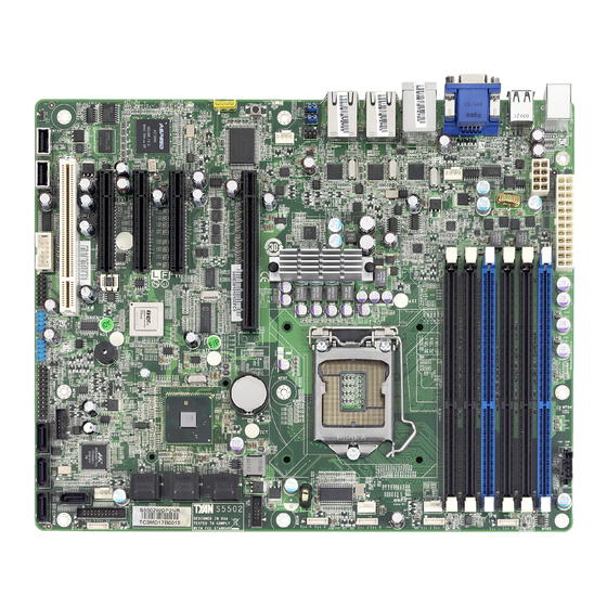
Page 12: Board Image
2.1 Board Image This picture is representative of the latest board revision available at the time of publishing. The board you receive may not look exactly like the above picture. http://www.tyan.com... -
Page 13: Block Diagram
2.2 Block Diagram http://www.tyan.com... -
Page 14: Board Parts, Jumpers And Connectors
2.3 Board Parts, Jumpers and Connectors This diagram is representative of the latest board revision available at the time of publishing. The board you receive may not look exactly like the above diagram. But for the DIMM number please refer to the above placement for memory installation. - Page 15 Jumpers & Connectors Jumper/Connector Function J8/J9/J30/J32/J33 4-pin Fan connector J37/J38/J39/J40/J42 8-pin 4096 fan header J19/J20 USB Front Panel Header USB3/USB4 Type-A USB Connectors TYFP1 Header COM2 Header Clear CMOS Jumper Chassis Intrusion Jumper JP1/JP2 COM switch IPMB Connector Enable/Disable BMC jumper PSMI Connector Speaker Header Port80 Header...
- Page 16 Rear Fan1 CPUFAN0 FrontFAN1 Rear Fan2 FrontFAN2 http://www.tyan.com...
- Page 17 J8/J9/J30/J32/J33: 4-Pin FAN Connector J32: CPUFAN0 J9: RearFAN1 J8: RearFAN2 Pin_1 J33: FrontFAN1 J30: Front FAN2 Use these headers to connect the cooling fans to the motherboard to keep the system stable and reliable. Pin 1 Pin 2 Pin 3 Pin 4 Fan PWM (speed) +12V...
- Page 18 http://www.tyan.com...
- Page 19 J22: TYFP1 Header Signal Signal Power LED+ 3.3V ID LED+ Power LED- ID LED- HD LED+ Fault_LED1- HD LED- Fault_LED2- Power SW# LAN1 ACTLED+ GND1 LAN1 ACTLED- Reset SW# SMBUS SDA GND2 SMBUS SCL ID SW INTRU# Temp Sensor LAN2 ACTLED+ NMI_SW# LAN2 ACTLED- J15: COM2 Connector...
- Page 20 http://www.tyan.com...
- Page 21 JP1/JP2: COM Switch Pin_1 Pin 1-2 Closed: COM2 (Default) Pin_1 Pin 2-3 Closed: BMC UART2 to COM2 J2: IPMB Connector Signal Signal IPMB_DATA IPMB_CLK J6: Enable/Disable BMC jumper Pin1-2 Closed: Disable BMC J25: PSMI Connector Signal Signal SMB_CLK SMB_DAT SMBALERT V3P3 JP5: Speaker Header Signal...
- Page 22 http://www.tyan.com...
- Page 23 J21: LAN3 LED Header (Reserved for Barebone) Signal Signal LAN3 LED- LAN3 LED+ J23: SAS GPIO to Backplane Signal Signal SMBCLK SDATAIN SMBDAT SDATAOUT SLOAD SCLOCK HD_ERR_LED J36: PCH SGPIO Signal Signal SMBCLK SDATAOUT0 SMBDAT SDATAOUT1 SLOAD SCLOCK HD_ERR_LED J35: 2X10_pin fan connector for Barebone Backplane Signal Signal FANIN1...
-
Page 24: Installing The Processor
Specifications on page 5. Check our website at http://www.tyan.com for latest processor support. MiTAC is not liable for damage as a result of operating an unsupported configuration. The diagram is provided as a visual guide to help you to install the socket processor and may not be an exact representation of the processor you have. - Page 25 Step4: Align the processor cutouts to match the two socket pins, and insert the processor into the socket Step5: Close the load plate (see letter “A”), close the socket lever, and ensure the load plate tab engages under the socket lever when fully closed (see letter “B”...
-
Page 26: Heat Sink Installation
2.5 Heat sink Installation After installing the processor, you should proceed to install the heat sink. The CPU heat sink will ensure that the processor do not overheat and continue to operate at maximum performance for as long as you own them. The overheated processor is dangerous to the motherboard. -
Page 27: Thermal Interface Material
Once you have finished installing all the fans you can connect your drives (hard drives, CD-ROM drives, etc.) to your motherboard. Adequate system airflow is required to ensure SAS controller and attached drives work properly. It is the responsibility of the NOTE system builder to ensure adequate system airflow by choosing the correct chassis and system components. -
Page 28: Tips On Installing Motherboard In Chassis
2.7 Tips on Installing Motherboard in Chassis Before installing your motherboard, make sure your chassis has the necessary motherboard support studs installed. These studs are usually metal and are gold in color. Usually, the chassis manufacturer will pre-install the support studs. If you are unsure of stud placement, simply lay the motherboard inside the chassis and align the screw holes of the motherboard to the studs inside the case. - Page 29 Some chassis’ include plastic studs instead of metal. Although the plastic studs are usable, MiTAC recommends using metal studs with screws that will fasten the motherboard more securely in place. Below is a chart detailing what the most common motherboard studs look like and how they should be installed.
-
Page 30: Installing The Memory
2.8 Installing the Memory Before installing memory, ensure that the memory you have is compatible with the motherboard and processor. Check the TYAN® web site at www.tyan.com for details of the type of memory recommended for your motherboard. The following diagram shows common memory modules: The TYAN®... - Page 31 ® For a complete list of supported memory, remember to visit TYAN ’s Website at http://www.tyan.com. Refer to the following table for channel slot configuration. S5502 Memory Configuration Channel A Channel B RDIMM UDIMM Note: For the DIMM number, please refer to the motherboard layout in section 2.3 Board Parts, Jumpers and Connectors on page 14 for memory installation.
- Page 32 Memory Installation Procedure Follow these instructions to install memory modules into the S5502. Press the locking levers in the direction shown in the following illustration. Align the memory module with the socket. The memory module is keyed to fit only one way in the socket. KEY SLOT Seat the module firmly into the socket by gently pressing down until it sits flush with the socket.
-
Page 33: Attaching Drive Cables
2.9 Attaching Drive Cables Attaching Serial ATA Cables S5502 is equipped with 6 Serial ATA (SATA) channels. Connections for the drives are very simple. There is no need to set Master/Slave jumpers on SATA drives. If you are in need of SATA/SAS cables or power adapters please contact your place of purchase. -
Page 34: Installing Add-In Cards
2.10 Installing Add-In Cards Before installing add-in cards, it’s helpful to know if they are fully compatible with your motherboard. For this reason, we’ve provided the diagrams below, showing the slots that may appear on your motherboard. PCI-E Gen. 2 x 16 slot (x16 signal) PCI-E x8 slot PCI 32 bit Slot Simply find the appropriate slot for your add-in card and insert the card firmly. -
Page 35: Connecting External Devices
2.11 Connecting External Devices Your motherboard supports a number of different interfaces through connecting peripherals. See the following diagrams for the details. PS/2 Port VGA Port LAN2 LAN3 LAN1 Share with BMC 2 X USB ports 2XUSB ports COM Port NOTE: Peripheral devices can be plugged straight into any of these ports but software may be required to complete the installation. -
Page 36: Installing The Power Supply
2.12 Installing the Power Supply There are two power connectors on your S5502. The S5502 requires 2 power inputs: PW1: 8-pin EPS 12V PWR connector Signal Signal +12V +12V +12V +12V http://www.tyan.com... - Page 37 PW2: 24-pin EPS 12V PWR main connector Signal Signal +3.3V +3.3V +3.3V -12V PS_ON PS_GD Reset 5VSB +12V +12V +3.3V Applying power to the board: 1. Connect the 12V 8-pin power connector. 2. Connect the EPS/12V 24-pin power connector. 3. Connect power cable to power supply and power outlet. You must always unplug the power connector to the motherboard NOTE before performing system hardware changes to avoid damaging...
-
Page 38: Finishing Up
2.13 Finishing Up Congratulations on making it this far! You have finished setting up the hardware aspect of your computer. Before closing up your chassis, make sure that all cables and wires are connected properly, especially IDE cables and most importantly, jumpers. -
Page 39: Chapter 3: Bios Setup
Chapter 3: BIOS Setup 3.1 About the BIOS The BIOS is the basic input/output system, the firmware on the motherboard that enables your hardware to interface with your software. The BIOS determines what a computer can do without accessing programs from a disk. The BIOS contains all the code required to control the keyboard, display screen, disk drives, serial communications, and a number of miscellaneous functions. - Page 40 Chipset section unless you are absolutely sure of what you are doing. The Chipset defaults have been carefully chosen either by MiTAC or your system manufacturer for best performance and reliability. Even a seemingly small change to the Chipset setup options may cause the system to become unstable or unusable.
-
Page 41: Bios Main Menu
3.2 BIOS Main Menu In this section, you can alter general features such as the date and time. Note that the options listed below are for options that can directly be changed within the Main Setup screen. BIOS Version This displays the version of BIOS. Processor This displays the CPU model and frequency. -
Page 42: Bios Advanced Menu
3.3 BIOS Advanced Menu This section facilitates configuring advanced BIOS options for your system. 3.3.1 Advanced CPU Configuration This section allows you to fine-tune the processor options. Ratio CMOS Setting [Auto] This feature is used to set the ratio between CPU core Clock and FSB frequency. Hardware Prefecther / Adjacent Cache Line Prefetch For UP platforms, leave it enabled. - Page 43 When enabled, a VMM can utilize the additional HW caps. Provided by Intel Virtualization Tech. Note: A full reset is required to change the setting. Disabled / Enabled Execute-Disable Bit Capability When disabled, force the XD feature flag to always return 0 Disabled / Enabled Intel®...
- Page 44 3.3.2 Advanced SATA Configuration Configure SATA as Select legacy IDE or RAID or AHCI as the SATA interface. SATA #1 IDE Configuration This feature is used to select SATA controller mode. In “compatible mode”, SATA and PATA drives are auto-detected and placed in Legacy mode. In “Enhanced (non-AHCI) mode”, SATA and PATA drives are auto-detected and placed in Native IDE mode.
- Page 45 3.3.3 Super I/O Configuration This setting allows you to configure Serial Port1 Base Addresses. Disabled / 3F8/IRQ4 /3E8/IRQ4 / 2E8/IRQ3 This setting allows you to configure Serial Port2 Base Addresses. Disabled / 2F8/IRQ3 /3E8/IRQ4 / 2E8/IRQ3 This setting allows you to configure Serial Port2 Mode. Normal / IrDA/ ASK IR http://www.tyan.com...
- Page 46 3.3.4 ACPI Configuration 3.3.4.1General ACPI Configuration http://www.tyan.com...
- Page 47 Suspend Mode Select the ACPI state used for System Suspend. Auto / S1(POS) / S3(STR) Repost Video on S3 Resume Determine whether to invoke VGA BIOS post on S3/STR resume. No / Yes 3.3.4.2 Advanced ACPI Configuration ACPI Version Features Set this value to allow or prevent the system to be complaint with the ACPI 2.0 specification.
- Page 48 NOTE: OEMB table is used to pass POST data to the AMI code during ACPI O/S operations. Headless Mode Enable or disable Headless operation mode through ACPI. Disabled / Enabled 3.3.4.3 Chipset ACPI Configuration ACPI APIC SCI IRQ Enable / Disable ACPI APIC SCI IRQ. Disabled / Enabled USB Device Wakeup From S3/S4 Enable/disable the USB device to wake up from S3/S4 state.
- Page 49 3.3.5 AHCI Configuration AHCI BIOS Support Enable for supporting AHCI. Enabled / Disabled AHCI CD/DVD Boot Time out Some SATA CD/DVD in AHCI mode need to wait ready longer. 0~35 (at 5 interval) http://www.tyan.com...
- Page 50 3.3.6 W83793 Hardware Health Configuration Auto Fan Control FAN power duty cycle is auto dynamic programmed in selected temperature range. Disabled: Fan Power On. Enabled: Fan Power Duty Cycle=50% (32 C)—100% (0 C), see max (CPUs, SIO) temperature Enabled / Disabled PWM Cycle Duty Cycle control range: 60%-100%...
- Page 51 3.3.8 Intel VT-d Configuration Intel VT-d Enable or disable Intel® Virtualization Technology for Directed I/O (VT-d) support. VT-d support on Intel platforms provides the capability to ensure improved isolation of I/O resources for greater reliability, security, and availability. Enabled / Disabled 3.3.9 Intel PCI-Express Configuration Active State Power Management Enable/disable PCI Express L0s AND L1 link power states.
- Page 52 3.3.10 Remote Access Configuration Remote Access Enables remote access to system through serial port. Disabled / Enabled 3.3.11 USB Configuration Legacy USB Support Enables support for legacy USB. AUTO option disables legacy support if no USB devices are connected. Enabled / Disabled / Auto USB 2.0 Controller Mode Configure the USB 2.0 controller in Hi Speed (480 Mbps) or Full Speed (12Mbps).
- Page 53 http://www.tyan.com...
-
Page 54: Pci/Pnp
3.4 PCI/PnP Clear NVRAM Clear NVRAM during system Boot. No / Yes Plug & Play O/S No: lets the BIOS configure all the devices in the system. Yes: lets the operating system configure Plug and Play (PnP) devices not required for boot if your system has a Plug and Play operating system. -
Page 55: Boot
Some PCI IDE cards may require this to be set to the PCI slot number that is holding the card. Auto / PCI Slot1/ PCI Slot2/ PCI Slot3/ PCI Slot4/ PCI Slot5/ PCI Slot6 3.5 Boot 3.5.1 Boot Settings Configuration Quick Boot This option allows user bypass BIOS self test during POST. - Page 56 PS/2 Mouse Support Select support for PS/2 Mouse. Auto / Enabled / Disabled Wait for ‘F1’ If Error Waits for F1 key to be present if error occurs. Enabled / Disabled Hit DEL Message Display Displays “Press DEL to run Setup” in POST. Enabled / Disabled Interrupt 19 Capture Enabled: allows option ROMs to trap interrupt 19.
- Page 57 3.5.2 Boot Device Priority http://www.tyan.com...
-
Page 58: Security
3.6 Security Boot Sector Virus Protection When it is set to [Enabled], BIOS will issue a virus warning message and beep if a write to the boot sector or the partition table of the HDD is attempted. Disabled / Enabled http://www.tyan.com... -
Page 59: Chipset
3.7 Chipset 3.7.1 North Bridge Configuration Memory Remap Feature [Enable]: Allow remapping of overlapped PCI memory above the total physical memory. [Disable]: Don’t allow remapping of memory. Enabled / Disabled Fast MRC [Enable]: While cold booting, MRC directly restores memory data from valid NVRAM without hardware training. - Page 60 Memory Hole This setting allows you to enable or disable the 1MB of memory required by some ISA expansion cards. Disabled / 15MB-16MB DRAM Margin Ranks Disabled / Enabled Initiate Graphic Adapter This setting allows you to select which graphics controller to use as the primary boot device.
- Page 61 3.7.2 South Bridge Configuration Restore On AC Power Loss Configure how the system board responds to a power failure. Power Off / Power On / Last State 3.7.3 ME Subsystem Configuration BootBlock HECI Message Enabled / Disabled HECI Message Enabled / Disabled End of Post S5 HECI Message Enabled / Disabled http://www.tyan.com...
- Page 62 3.7.4 Onboard Peripherals Configuration http://www.tyan.com...
-
Page 63: Exit
3.8 Exit Save Changes and Exit Use this option to exit setup utility and re-boot. All new selections you have made are stored into CMOS. System will use the new settings to boot up. Discard Changes and Exit Use this option to exit setup utility and re-boot. All new selections you have made are not stored into CMOS. - Page 64 NOTE http://www.tyan.com...
-
Page 65: Chapter 4: Diagnostics
Chapter 4: Diagnostics NOTE: if you experience problems with setting up your system, always check the following things in the following order: Memory, Video, CPU By checking these items, you will most likely find out what the problem might have been when setting up your system. -
Page 66: Amibios Post Code
4.3 AMIBIOS Post Code The POST code checkpoints are the largest set of checkpoints during the BIOS pre- boot process. The following table describes the type of checkpoints that may occur during the POST portion of the BIOS: Checkpoint Description Disable NMI, Parity, video for EGA, and DMA controllers. - Page 67 Checkpoint Description Displaying sign-on message, CPU information, setup key message, and any OEM specific information. Initializes different devices through DIM. See DIM Code Checkpoints section of document for more information. Initializes DMAC-1 & DMAC-2. Initialize RTC date/time. Test for total memory installed in the system. Also, Check for DEL or ESC keys to limit memory test.
- Page 68 NOTE http://www.tyan.com...
-
Page 69: Appendix: How To Make A Driver Diskette
Appendix: How to Make a Driver Diskette ® Follow the steps below to make a driver diskette from the TYAN driver CD provided. ® Start the system and insert the TYAN CD into the CD-ROM drive to boot from CD. You will see the following menu. Then press [1] and [Enter] to boot the ®... - Page 70 The following picture pops up after selecting the chipset model. TYAN Driver Diskette Maker ** nVidia ** ====Choose Chipset Model==== nVidia NVRAID EXIT After selecting the chipset model, select the OS to start the diskette making. TYAN Driver Diskette Maker ====Example Chipset Driver==== Diskette =01= Microsoft Windows 2000 32-bit...
- Page 71 Glossary ACPI (Advanced Configuration and Power Interface): a power management specification that allows the operating system to control the amount of power distributed to the computer’s devices. Devices not in use can be turned off, reducing unnecessary power expenditure. AGP (Accelerated Graphics Port): a PCI-based interface which was designed specifically for demands of 3D graphics applications.
- Page 72 Bus: a data pathway. The term is used especially to refer to the connection between the processor and system memory, and between the processor and PCI or ISA local buses. Bus mastering: allows peripheral devices and IDEs to access the system memory without going through the CPU (similar to DMA channels).
- Page 73 DRAM (Dynamic RAM): widely available, very affordable form of RAM which looses data if it is not recharged regularly (every few milliseconds). This refresh requirement makes DRAM three to ten times slower than non-recharged RAM such as SRAM. ECC (Error Correction Code or Error Checking and Correcting): allows data to be checked for errors during run-time.
- Page 74 I/O (Input/Output): the connection between your computer and another piece of hardware (mouse, keyboard, etc.) IRQ (Interrupt Request): an electronic request that runs from a hardware device to the CPU. The interrupt controller assigns priorities to incoming requests and delivers them to the CPU. It is important that there is only one device hooked up to each IRQ line;...
- Page 75 RAID (Redundant Array of Independent Disks): a way for the same data to be stored in different places on many hard drives. By using this method, the data is stored redundantly and multiple hard drives will appear as a single drive to the operating system.
- Page 76 application Depending on the , NVIDIA SLI can deliver as much as two times the performance of a single GPU configuration. Standby mode: in this mode, the video and hard drives shut down; all other devices continue to operate normally. UltraDMA-33/66/100: a fast version of the old DMA channel.
- Page 77 Technical Support If a problem arises with your system, you should first turn to your dealer for direct support. Your system has most likely been configured or designed by them and they should have the best idea of what hardware and software your system contains.
- Page 78 Note: A receipt or copy of your invoice marked with the date of purchase is required before any warranty service can be rendered. You may obtain service by calling the manufacturer for a Return Merchandise Authorization (RMA) number. The RMA number Should be prominently displayed on the outside of the shipping carton and the package should be ®...
Need help?
Do you have a question about the TYAN S5502 and is the answer not in the manual?
Questions and answers