Table of Contents
Advertisement
Quick Links
Advertisement
Table of Contents

Related Manuals for MiTAC PD10AI


Summary of Contents for MiTAC PD10AI
- Page 1 MITAC Desktop Board PD10AI Product Guide...
-
Page 2: Desktop Board Features
Desktop Board Features This chapter briefly describes the features of Desktop Board PD10AI. to summarizes the major features of the Desktop Board. Below Feature Summary TAC D PD10AI F ABLE ESKTOP OARD EATURES Low-profile Mini-ITX (20 millimeters [0.79 inches] x 170.18 Form Factor millimeters [6.7 inches] x 170.18 millimeters [6.7 inches]) - Page 3 • Support for Advanced Configuration and Power Interface (ACPI), and System Management BIOS (SMBIOS) Nuvoton NCT6793D based subsystem, including: Hardware • Voltage sense to detect out of range power supply voltages Management • Thermal sense to detect out of range thermal values •...
-
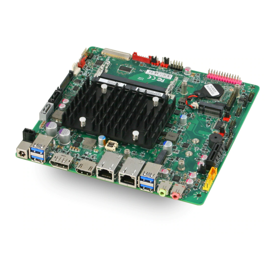
Page 4: Desktop Board Components
Desktop Board Components Figure shows the approximate location of the major components on the top side of MiTAC Desktop Board PD10AI. Figure: MiTAC Desktop Board PD10AI Components (Top) - Page 5 TAC D PD10AI C ABLE ESKTOP OARD OMPONENTS Back Panel Connectors 12V 2-PIN DC-in M.2 Key-E SATA 7-Pin Connector Com2 RS232 Power Select SATA Power Connector SO-DIMM slot CPU Fan Header System Fan Header Chassis Front I/O Header LVDS Connector (eDP Connector at the bottom side)
-
Page 6: System Memory
Processor MITAC Desktop Board PD10AI includes a passively-cooled, Intel Apollo Lake N3350/N4200 processor with integrated graphics and memory controller. The processor is soldered to the Desktop Board and is not customer upgradeable. NOTE The board is designed to be passively cooled in a properly ventilated chassis. Chassis venting locations are recommended above the processor heatsink area for maximum heat dissipation effectiveness. -
Page 19: General Overview
GENERAL OVERVIEW This document specifies the BIOS requirements for PD10AI Note: The BIOS specification may be changed depend on hardware design. This is based on the product specification document (PRD). HARDWARE OVERVIEW 1.1.1 - Intel Apollo Lake N4200/N3350 1.1.2 System Memory... - Page 20 Dual-Port USB2.0 Header Chassis main panel header (2x5) (Black w/multi color) BIOS Recovery Header/Jumper Audio header (front panel mic/hp) (2x5) Onboard Speaker header SATA power (15pin SATA power) 2 Serial Port Headers , configurable for power RS232 Jump for AT/ATX mode Parallel Port Header MiAPI Header co-lay with optional 1x parallel port header (2x13) Legacy IO board header...
- Page 21 GPIO Pin Definition 1.1.14 BIOS programming/ Pin Name Selected Function/Net Name Comment GPIO_205 / PCIE_WAKE0_N GPI/ PCIE_WAKE0_N / M2E_WAKE_0_N 1.8V PU 10K to V_1P8_A GPIO_206 / PCIE_WAKE1_N GPI / PCIE_WAKE1_N / GLAN0_WAKE_1_N 1.8V PU 10K to V_1P8_A GPIO_207 / PCIE_WAKE2_N GPI / PCIE_WAKE2_N / X1_WAKE_2_N...
- Page 22 1.8V GPIO_169 / SDIO_D2 GPO/ 1.8V GPIO_170 / SDIO_D3 GPO/ 1.8V GPIO_171/ SDIO_CMD GPO/ 1.8V GPIO_172 / SDCARD_CLK GPO/ AB58 1.8V GPIO_173 / SDCARD_D0 GPO/ AC49 1.8V GPIO_174 / SDCARD_D1 GPO/ AC48 1.8V GPIO_175 / SDCARD_D2 GPO/ AC51 1.8V GPIO_176 / SDCARD_D3 GPO/ AB51 1.8V...
- Page 23 1.8V GPIO_130 / LPSS_I2C3_SDA GPO/ AM62 1.8V GPIO_131 / LPSS_I2C3_SCL GPO/ AL62 1.8V GPIO_132 / LPSS_I2C4_SDA GPO/ AP52 1.8V GPIO_133 / LPSS_I2C4_SCL GPO/ AP54 1.8V GPIO_134 / LPSS_I2C5_SDA GPO/ AP49 1.8V GPIO_135 / LPSS_I2C5_SCL GPO/ AP51 1.8V GPIO_136 / LPSS_I2C6_SDA GPO/ AL63 1.8V...
- Page 24 1.8V GPIO_155 / ISH_GPIO_9 Fn2: SPKR AUD_SPKR AK57 1.8V AUD_SPKR TO AUDIO CODE GPIO_209 / PCIE_CLKREQ0_N PCIE_CLKREQ0_N/ Native/ AK62 1.8V M2E_CLKREQ_0 PU 10K to V_1P8_A GPIO_210 / PCIE_CLKREQ1_N PCIE_CLKREQ1_N/ Native/ AH62 1.8V PU_LAN0_CLKREQ_1 PU 10K to V_1P8_A GPIO_211 / PCIE_CLKREQ2_N PCIE_CLKREQ2_N/ Native/ AH61...
- Page 25 1.8V GPIO_199 / HV_DDI1_HPD Fn2: DDI1_HPD Native/ Enable 20k pull up 1.8V DP_HP_DET_PCH PU 8.2K to V_1P8_A GPIO_200 / HV_DDI0_HPD Fn2: DDI0_HPD Native/ Enable 20k pull up 1.8V HDMI_HPD_N PU 8.2K to V_1P8_A GPIO_201 / MDSI_A_TE GPO/ 1.8V GPIO_202 / MDSI_C_TE GPO/ 1.8V...
- Page 26 1.8V GPIO_82 / AVS_DMIC_CLK_AB2 GPO/ strapping) RSVD_GPIO_82 1.8V PD 10K to GND GPIO_83 / AVS_DMIC_DATA_2 GPO/ 1.8V GPIO_84 / AVS_I2S2_MCLK Fn 2: AVS_HDA_RST_N AVS_HDA_RST_N/ 1.8V HDA_RST- TO AUDIO CODE GPIO_85 / AVS_I2S2_BCLK GPO/ 1.8V GPIO_86 / AVS_I2S2_WS_SYNC GPO/ 1.8V GPIO_87 / AVS_I2S2_SDI GPO/ 1.8V GPIO_88 / AVS_I2S2_SDO...
- Page 27 1.8V PD 10K to GND GPIO_105 / FST_SPI_0_FS0 GPO/ strapping) RSVD_GPIO_105 1.8V PD 10K to GND GPIO_106 / FST_SPI_0_FS1 GPO/ strapping) RSVD_GPIO_106 1.8V PU 10K to V_1P8_A GPIO_109 / FST_SPI_0_RXD 1.8V GPIO_110 / FST_SPI_0_TXD GPO/ strapping) LPC_MODE_SET 1.8V PD 10K to GND GPIO_111 / SIO_SPI_1_CLK GPO/ strapping)
- Page 28 1.8V GPIO_4 GPO/ 1.8V GPIO_5 GPO/ 1.8V GPIO_6 GPO/ 1.8V GPIO_7 GPO/ SOC_TPM_ENABLE_N 1.8V PU 10K to V_1P8_A GPIO_8 GPO/ MUX_SEL_EN_PMC 1.8V PU 10K to V_1P8_A GPIO_9 GPI/ DISPLAY_RESET_N 1.8V PU 10K to V_1P8_A GPIO_10 GPO/ INT_SPK_SD_N 1.8V PU 10K to V_1P8_A GPIO_11 GPI/ BRIGHTNESS_DOWN_PMC...
- Page 29 1.8V PU 10K to V_1P8_A GPIO_23 GPI/ MSATA_DET_N 1.8V PU 10K to V_1P8_A GPIO_24 GPI/ PMU_PME_N 1.8V PU 10K to V_1P8_A GPIO_25 Fn 5: SATA_DEVSLP1 SATA_DEVSLP1 1.8V DEVLSP1 TO M.2 Key B Slot GPIO_26 Fn 5: SATA_LEDN SATA_LEDN 1.8V SATA_LED_N GPIO_27 GPO/ LAN0_DISABLE_N...
- Page 30 1.8V GPIO_42 / LPSS_UART1_RXD GPO/ 1.8V GPIO_43 / LPSS_UART1_TXD GPO/ strapping) RSVD_GPIO_43 1.8V PD 10K to GND GPIO_44 / LPSS_UART1_RTS_N GPO/ strapping) BOOT_SPI_SET 1.8V PU 10K to V_1P8_A GPIO_45 / LPSS_UART1_CTS_N GPO/ 1.8V GPIO_46 / LPSS_UART2_RXD GPO/ 1.8V GPIO_47 / LPSS_UART2_TXD GPO/ strapping) CSE_FW_SET...
- Page 31 1.8V GPIO_73 / GP_CAMERASB11 GPO/ 1.8V GPIO_216 GPI/ LEGACY_IO_DET_N_R 1.8V PU 10K to V_1P8_A GPIO_217 GPI/ BOARD_ID_0 1.8V PU 10K to V_1P8_A GPIO_218 GPI/ BOARD_ID_1 1.8V PU 10K to V_1P8_A GPIO_219 / EMMC_RST_N 1.8V...
- Page 32 REFERENCES CPU Specification : 557555_APL_EDS_1p5_Volume_1.pdf 557556_EDS_Volume_2_Revision_0p7.pdf 557557_EDS_Volume_3_Revison_0p7.pdf 559360_Volume_4_EDS_0p7_Unstructured_Final.pdf Trusted Execution Engine Specification 562802_APL_BXT_TXEFWCompGuide_Rev0p85.pdf Super I/O Specification : NCT6793D_Datasheet_V1_0.pdf Others : 559810_APL_BXT_IAFW_Vol1_BIOSSpec_Rev_0p7p1.pdf 559811_APL_BXT_IAFW_Vol2_BIOSSpec_Rev_0p7p1.pdf 561027_APL_RMT_UG_Rev0p6.pdf...
-
Page 33: Bios Overview
BIOS OVERVIEW AMI APTIO Core 5.011 Code Base : 1ATJS010 Support Platform : Intel Apollo Lake Support Intel GOP VBIOS : 10.0.1027(64bit) Provide BIOS Setup Utility Support Advanced Configuration and Power Interface (ACPI 2.0 or later) Support DMI 2.3.1 or later Support BIOS Boot Specification 1.01 or higher Support Plug and Play 1.0a, PCI Express 1.0a Support USB 1.1 / 2.0 / 3.0... -
Page 34: Splash Screen
POST OVERVIEW When a computer is turned on, the BIOS runs a Power-On Self Test (POST). Program execution start at memory location F000:FFF0h. This address is part of ROM BIOS and contains a jump command to a series of BIOS routines that test and initialize the hardware components. POST consists of various test and initialization routines for chipset’... -
Page 35: Power Management
The Subsystem Vendor ID is that of the board/card manufacturer. The Subsystem Device ID is assigned by the subsystem vendor. For on-brand board/system, BIOS needs to configure MiTAC SVID as manufacturer ID (to identify for DTM verification) & SSID (used project code). - Page 36 [System Information] (Type 1) Manufacturer (String1) - "MiTAC" Product Name (String2) - "PD10AI" Version (String3) - " " Serial Number (String4) - " " UUID: 0x00 0x02 0x00 0x03 0x00 0x04 0x00 0x05 0x00 0x06 0x00 0x07 0x00 0x08 0x00 0x09...
-
Page 37: Bios Flash
Height: 0x00 (0) Number of Power Cords: 0x01 (1) Contained Element Count: 0x00 (0) Element Record Length: 0x00 (0) SKU Number (String5) - " " UTILITIES BIOS FLASH If BIOS supports multi BIOS ROM, the flash utility should support them. Vender Name Model Name Winbond... - Page 38 BIOS RELEASE BIOS REVISION D767 0 A 01 MiTAC BIOS Naming: SKU B/C 1 Sku ID; “0” for MiTAC Stage; =>Develop Stage. =>Test Stage. =>Production Stage Version number (Decimal); RELEASE COMPONENT Release BIOS ROM and Flash Utility for each BIOS release. If Flash Utility is not modified, may not release Flash Tool.
- Page 39 // Checksum : // ValleyView MRC Version : //******************************************************************************** // MicroCode revision & CPU Support List : //M0230671116 ("Intel(R) ValleyView A-0 Stepping") //M0230672219 ("Intel(R) ValleyView B-1 Stepping") //M0C3067330C("Intel(R) ValleyView B-2 Stepping") //******************************************************************************** // Reference Code revision : // ValleyView: reference code ver. // NorthBridge ValleyView - SystemAgent: reference code ver.
- Page 40 10.2 BIOS QA TEST Must to PASS below tests before release BIOS version (correct version) BIOS Setup (including "Restore Defaults", "Discard Changes" and clear CMOS) (follow spec) S3/S4/S5 power cycling tests over 100 times (without any error) Hot Keys (function normal) Windows Device manager (no “!”) BIOS Flash (successful &...
- Page 41 Standard Status Codes SEC Status Codes Status Code Description Not used Progress Codes Power on. Reset type detection (soft/hard). AP initialization before microcode loading North Bridge initialization before microcode loading South Bridge initialization before microcode loading OEM initialization before microcode loading Microcode loading AP initialization after microcode loading North Bridge initialization after microcode loading...
- Page 42 0x1A Pre-memory South Bridge initialization (South Bridge module specific) 0x1B Pre-memory South Bridge initialization (South Bridge module specific) 0x1C Pre-memory South Bridge initialization (South Bridge module specific) 0x1D – 0x2A OEM pre-memory initialization codes 0x2B Memory initialization. Serial Presence Detect (SPD) data reading 0x2C Memory initialization.
- Page 43 0x5A Internal CPU error 0x5B reset PPI is not available 0x5C-0x5F Reserved for future AMI error codes S3 Resume Progress Codes 0xE0 S3 Resume is stared (S3 Resume PPI is called by the DXE IPL) 0xE1 S3 Boot Script execution 0xE2 Video repost 0xE3...
- Page 44 0x63 CPU DXE initialization is started 0x64 CPU DXE initialization (CPU module specific) 0x65 CPU DXE initialization (CPU module specific) 0x66 CPU DXE initialization (CPU module specific) 0x67 CPU DXE initialization (CPU module specific) 0x68 PCI host bridge initialization 0x69 North Bridge DXE initialization is started 0x6A North Bridge DXE SMM initialization is started...
- Page 45 0x9D USB Enable 0x9E – 0x9F Reserved for future AMI codes 0xA0 IDE initialization is started 0xA1 IDE Reset 0xA2 IDE Detect 0xA3 IDE Enable 0xA4 SCSI initialization is started 0xA5 SCSI Reset 0xA6 SCSI Detect 0xA7 SCSI Enable 0xA8 Setup Verifying Password 0xA9 Start of Setup...
- Page 46 0xD7 No Console Input Devices are found 0xD8 Invalid password 0xD9 Error loading Boot Option (LoadImage returned error) 0xDA Boot Option is failed (StartImage returned error) 0xDB Flash update is failed 0xDC Reset protocol is not available DXE Beep Codes None ASL Status Codes Status Code Description...
Need help?
Do you have a question about the PD10AI and is the answer not in the manual?
Questions and answers