
Subscribe to Our Youtube Channel
Related Manuals for MiTAC PD11TGS


Summary of Contents for MiTAC PD11TGS
- Page 1 PD11TGS User Manual V1.0 mbedded 3.5” SBC Intel® Tiger Lake-UP3 Core-i/Celeron Processors Performance, Versatile, and Reliable...
- Page 2 MiTAC Corp., Ltd. All information and specification provided in this manual are for reference only and remain subject to change without prior notice.
- Page 3 WARNING! / AVERTISSEMENT! Always completely disconnect the power cord from your chassis whenever you work with the hardware. Do not make connections while the power is on. Sensitive electronic components can be damaged by sudden power surges. Only experienced electronics personnel should open the PC chassis.
- Page 4 Ordering Information Model Number CPU Model Heatsink Configuration PD11TGS-6305E-HSK Celeron 6305E MB + Heatsink PD11TGS-1115G4E-HSK i3-1115G4E MB + Heatsink PD11TGS-1145G7E-HSK i5-1145G7E MB + Heatsink PD11TGS-1185G7E-HSK i7-1185G7E MB + Heatsink...
- Page 5 Packing List Q’ty Item Description PD11TGS Embedded Motherboard SATA Power Cable SATA Signal Cable...
-
Page 6: Table Of Contents
CONTENTS CHAPTER 1: INTRODUCTION ........................ 8 1.1 Overview ..........................8 1.2 Product Features ........................8 1.3 Hardware Specification ......................9 1.4 Rear I/O Placement ......................11 CHAPTER 2: JUMPER SETTING AND PIN DEFINITION ................. 13 2.1 Jumper and Internal Connector Overall Placement ............. 13 2.2 Jumper Setting ........................ - Page 7 INTRODUCTION This chapter provides the PD11TGS Embedded Motherboard product overview, including features, hardware and mechanical specifications.
-
Page 8: Chapter 1: Introduction
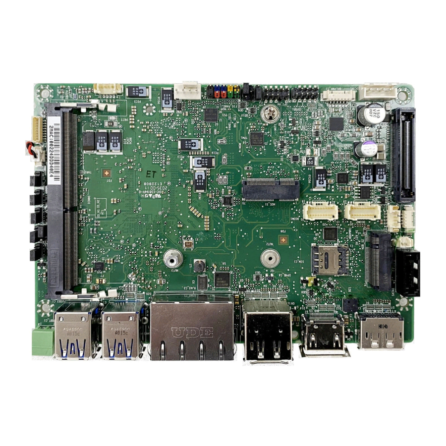
I/O placement. 1.1 Overview MiTAC’s PD11TGS embedded motherboard is the next generation embedded system with Intel® Gen. (10nm+ manufacturing process) Tiger Lake-UP3 processor which integrates Iris Xe outstanding graphic engine. The excellent graphic performance and performance processor provide the solution for every complicated task and most types of application. -
Page 9: Hardware Specification
1.3 Hardware Specification SYSTEM Core™ i /Celeron ULV Processor ® Gen Tiger Lake-UP3 Intel Celeron 6305E (Dual Core, 4MB Cache, up to 1.80 GHz) i3-1115G4E (Dual Core, 6MB Cache, up to 3.90 GHz) i5-1145G7E (Quad Core, 8MB Cache, up to 4.10 GHz) i7-1185G7E (Quad Core, 12MB Cache, up to 4.40 GHz) System Memory DDR4 3200 MHz / 1 x 260-pin SO-DIMM / Max. - Page 10 Rear I/O 1 x DisplayPort 1.2 2 x HDMI 1.4 2 x RJ-45 (1 for 2.5GbE LAN and 1 for 1GbE LAN) 4 x USB 3.1 Gen 2 (10 Gbps) 1 x 2-pin Terminal Block Remote Power on / off POWER REQUIREMENT Power Input 8~24V Wide Range DC Input w/ 4-pin header (Pitch 2.5mm)
-
Page 11: Rear I/O Placement
1.4 Rear I/O Placement... - Page 12 JUMPER SETTING AND PIN DEFINITION This chapter provides information about how to set up the jumper and use internal I/Os of PD11TGS Embedded Motherboard hardware.
-
Page 13: Chapter 2: Jumper Setting And Pin Definition
CHAPTER 2: JUMPER SETTING AND PIN DEFINITION This chapter provides information about how to set up the jumper, and use internal I/Os of PD11TGS Embedded Motherboard hardware. 2.1 Jumper and Internal Connector Overall Placement... -
Page 15: Jumper Setting
2.2 Jumper Setting... -
Page 16: Internal Connector Pin Definition
2.3 Internal Connector Pin Definition Standard Connectors... - Page 17 Special Connectors...
-
Page 20: External Connector Pin Definition
2.4 External Connector Pin Definition... - Page 21 BIOS SETUP This chapter provides information about how to set up BIOS and use BIOS menu items to adjust basic function settings.
-
Page 22: Chapter 3: Bios Setup
CHAPTER 3: BIOS SETUP This chapter provides information about how to set up BIOS and use BIOS menu items to adjust basic function settings. 3.1 Main Page Field Name BIOS Vendr Default Value American Megatrends Comment This field is not selectable. There is no help text associated with it. Field Name BIOS Version Default Value... - Page 23 Value Display the installed CPU brand. Comment This field is not selectable. There is no help text associated with it. Field Name Microcode Version Value Display the CPU microcode revision. Comment This field is not selectable. There is no help text associated with it. Field Name Total Memory Value...
-
Page 24: Advanced Page
3.2 Advanced Page Field Name Onboard Device Help Onboard Device Configuration. Comment Press Enter when selected to go into the associated Sub-Menu. Field Name CPU Configuration Help CPU Configuration Parameters. Comment Press Enter when selected to go into the associated Sub-Menu. Field Name Power &... - Page 25 Field Name HW Monitor Help Monitor hardware status Comment Press Enter when selected to go into the associated Sub-Menu. Field Name S5 RTC Wake Settings Help Enable system to wake from S5 using RTC alarm Comment Press Enter when selected to go into the associated Sub-Menu. Field Name Network Stack Configuration Help...
- Page 26 3.2.1 Onboard Device Field Name Turbo Mode Default Value [Enabled] Possible Value Enabled Disabled Help Enable/Disable processor Turbo Mode (requires EMTTM enabled too) Field Name State After G3 Default Value [S5 State] Possible Value S0 State S5 State Help Specify what state to go to when power is re-applied after a power failure (G3 state).
- Page 27 Internal Graphics Device. Field Name DVMT Total Gfx Mem Default Value [256M] Possible Value 128M 256M Help Select DVMT5.0 Total Graphic Memory size used by the Internal Graphics Device. Field Name Wake on LAN Enable Default Value [Enabled] Possible Value Enabled Disabled Help...
- Page 28 data saved on it will be lost Field Name G-Sensor Enable/Disable Default Value [Disabled] Possible Value Enabled Disabled Help MS-26CAD-T10 G sensor on/off Notice : If Gsensor enabled will reserve 2 pin from DIO 3.2.2 CPU Configuration Field Name Type Default Value [Intel CPU Brand String] Comment...
- Page 29 Comment This field is not selectable. There is no help text associated with it. Field Name L1 Instruction Cache Default Value L1 Instruction Cache Size Comment This field is not selectable. There is no help text associated with it. Field Name L2 Cache Default Value L2 Cache Size...
- Page 30 3.2.3 Trusted Computing Field Name Firmware Version Default Value TPM module version. Comment This field is not selectable. There is no help text associated with it. Field Name Vendor Default Value TPM module vendor name. Comment This field is not selectable. There is no help text associated with it. Field Name Security Device Support Default Value...
- Page 31 3.2.4 NCT6126D Super IO Configuration Field Name Serial Port 1 Configuration Help Set Parameters of Serial Port 1 (COMC) Comment Press Enter when selected to go into the associated Sub-Menu. Field Name Serial Port 2 Configuration Help Set Parameters of Serial Port 2 (COMD) Comment Press Enter when selected to go into the associated Sub-Menu.
- Page 32 3.2.5 Serial Port 1 Configuration Field Name Serial Port Default Value [Enabled] Possible Value Disabled Enabled Help Enable or Disable Serial Port(COM) Field Name Device Settings Default Value Device Super IO COM1 Address and IRQ. Comment This field is not selectable. There is no help text associated with it. Field Name Mode Configuration Default Value...
- Page 33 3.2.6 Serial Port 2 Configuration Field Name Serial Port Default Value [Enabled] Possible Value Disabled Enabled Help Enable or Disable Serial Port(COM) Field Name Device Settings Default Value Device Super IO COM2 Address and IRQ. Comment This field is not selectable. There is no help text associated with it.
- Page 34 3.2.7 Serial Port 3 Configuration Field Name Serial Port Default Value [Enabled] Possible Value Disabled Enabled Help Enable or Disable Serial Port(COM) Field Name Device Settings Default Value Device Super IO COM3 Address and IRQ. Comment This field is not selectable. There is no help text associated with it.
- Page 35 3.2.8 Serial Port 4 Configuration Field Name Serial Port Default Value [Enabled] Possible Value Disabled Enabled Help Enable or Disable Serial Port(COM) Field Name Device Settings Default Value Device Super IO COM4 Address and IRQ. Comment This field is not selectable. There is no help text associated with it.
- Page 36 3.2.9 Hardware Monitor Type Range DIMM Temperature 70~-40℃ CPU VR Temperature 70~-40℃ Fan Speed There are many kinds of the fan could be installed into the system, so we could only set 0 RPM for the failed fan speed, and there is also no high RPM limitation.
- Page 37 3.2.10 RTC Wake Settings Field Name Wake system from S5 Default Value [Disabled] Possible Value Disabled Fixed Time Help Enable or disable System wake on alarm event, Select FixedTime, system will wake on the hr::min::sec specified. Field Name Wake up hour(Show when Wake system from S5 set to Fixed Time) Default Value Possible Value 0-23...
- Page 38 3.2.11 Network Stack Configuration Field Name Network stack Default Value [Disabled] Possible Value Disabled Enabled Help Enable/Disable UEFI Network stack. Field Name Ipv4 PXE Support (Available when Network stack Enabled) Default Value [Enabled] Possible Value Disabled Enabled Help Enable/Disable Ipv4 PXE Boot Support. If disabled IPV4 PXE boot support will not be available.
- Page 39 3.2.12 NVMe Configuration Field Name (Device) Comment Press Enter when selected to go into the associated Sub-Menu.
-
Page 40: Evnet Logs
3.3 Evnet logs Field Name Change Smbios Event Log Settings Help Press <Enter> to change the Smbios Event Log configuration. Comment Press Enter when selected to go into the associated Sub-Menu. Field Name View Smbios Event Log Help Press <Enter> to view the Smbios Event Log records. Comment Press Enter when selected to go into the associated Sub-Menu. - Page 41 3.3.1 Enabling/Disabling Options Field Name Smbios Event Log Default Value [Enable] Possible Value Disabled Enabled Help Change this to enable or disable all features of Smbios Event Logging during boot. Field Name Erase Event Log Default Value [No] Possible Value Yes, Next reset Yes, Every reset Help...
- Page 42 3.3.2 View Smbios Event log Field Name DATE / TIME / ERROR CODE / SEVERITY / COUNT Default Value MM/DD/YY HH:MM:SS Smbios 0x16 N/A N/A Possible Value By Events. Help By Events.
-
Page 43: Security Page
3.4 Security Page Field Name Administrator Password Help Set Administrator Password Field Name User Password Help Set User Password. Field Name HDD Security drive Help HDD Security Configuration for selected drive Comment Press Enter when selected to go into the associated Sub-Menu. Field Name Secure Boot Help... - Page 44 3.4.1 HDD Security Field Name Set User Password Help Set HDD User Password. *** Advisable to Power Cycle System after Setting Hard Disk Passwords ***.Discard or Save changes option in setup does not have any impact on HDD when password is set or removed. If the 'Set HDD User Password' option is hidden, do power cycle to enable the option again...
- Page 45 3.4.2 Secure Boot Field Name Secure Boot Default Value [Enabled] Possible Value Enabled Disabled Help Secure Boot feature is Active if Secure Boot is Enabled,Platform Key(PK) is enrolled and the System is in User mode.The mode change requires platform reset Field Name Secure Boot Mode Default Value...
- Page 46 Comment Enables expert users to modify Secure Boot Policy variables without full authentication...
- Page 47 3.4.3 Key Management (Secure Boot Mode set to Custom) Field Name Factory Key Provision Default Value [Disabled] Possible Value Enabled Disabled Help Install factory default Secure Boot keys after the platform reset and while the System is in Setup mode Field Name Restore Factory Keys Help...
- Page 48 Field Name Remove ‘UEFI CA’ from DB Help Device Guard ready system must not list 'Microsoft UEFI CA' Certificate in Authorized Signature database (db) Field Name Restore DB defaults Help Restore DB variable to factory defaults Field Name Platform Key (PK) Default Value Size:0, Keys:0, Key source: No Keys Help...
- Page 49 c)EFI_CERT_RSA2048 (bin) d)EFI_CERT_SHAXXX 2.Authenticated UEFI Variable 3.EFI PE/COFF Image(SHA256) Key Source: Factory,External,Mixed comment Press Enter when selected to go into the associated Sub-Menu. Field Name Authorized TimeStamps Default Value Size:0, Keys:0, Key source: No Keys Help Enroll Factory Defaults or load certificates from a file: 1.Public Key Certificate: a)EFI_SIGNATURE_LIST b)EFI_CERT_X509 (DER)
- Page 50 3.4.4 BIOS Update Field Name Path for ROM Image Help Enter the path to the Secure flash option...
-
Page 51: Boot Page
3.5 Boot Page Field Name Setup Prompt Timeout Default Value Possible Value 1~65535 Help Number of seconds to wait for setup activation key. 65535(0xFFFF) means indefinite waiting. Field Name Bootup NumLock State Default Value [Off] Possible Value Help Select the keyboard NumLock state Field Name Boot Option #1 Default Value... - Page 52 Default Value [USB CD/DVD] Possible Value USB Floppy, CD/DVD, USB CD/DVD, Hard Disk , USB Key, USB Hard Disk , NVME, Network, Disabled Help Sets the system boot order Field Name Boot Option #3 Default Value [Hard Disk] Possible Value USB Floppy, CD/DVD, USB CD/DVD, Hard Disk , USB Key, USB Hard Disk , NVME, Network, Disabled Help...
- Page 53 Comment Press Enter when selected to go into the associated Sub-Menu. Field Name (UEFI) USB Hard Disk Drive BBS Priorities Help Specifies the Boot Device Priority sequence from available USB Hard Disk Drives. Comment Press Enter when selected to go into the associated Sub-Menu. Field Name (UEFI) NVME Drive BBS Priorities Help...
- Page 54 3.5.1 (List Boot Device Type) Drive BBS Priorities Field Name Boot Option #1 Default Value Possible Value Boot Device Name 1 of this type, Disable Help Sets the system boot order...
-
Page 55: Save & Exit Page
3.6 Save & Exit Page Field Name Save Changes and Reset Help Reset the system after saving the changes. Field Name Discard Changes and Rest Help Reset system setup without saving any changes. Field Name Restore Defaults Help Restore/Load Default values for all the setup options.
Need help?
Do you have a question about the PD11TGS and is the answer not in the manual?
Questions and answers