Table of Contents
Advertisement
Quick Links
Advertisement
Table of Contents

Related Manuals for Showven uFlamer X1800


Summary of Contents for Showven uFlamer X1800
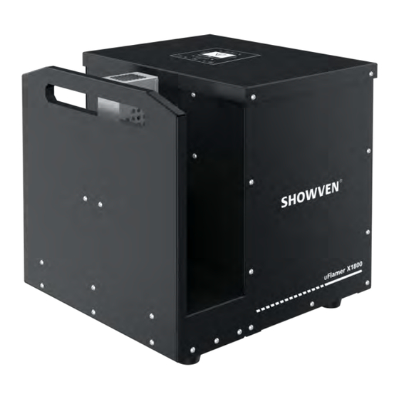
- Page 1 USER MANUAL uFlamer X1800 V1.1 2022.09...
-
Page 2: Functional Characteristics
Be sure to use high quality flame fluid according to below requirement, otherwise, it is easily leads to failure or danger. The operator responsible for the control of uFlamer X1800 must always have a clear view of the device, so that he/she can stop the show immediately when there is danger. The main AC power switch should near operator. -
Page 3: Technical Specifications
Flames up to 10m Stainless steel housing Built-in accumulator DMX control, both 3-pin and 5-pin XLR Technical Specifications Δ Model: uFlamer X1800 Dimension: 370× 380× 380mm Weight: 19 kg Input: 220V, 110V Quick Coupler: ISO7241B G1/4 male Work Power: 260W... -
Page 4: Rear Panel
Diagram of bottom panel Rear Panel Display area Pressure gauge Fuel IN quick coupler (ISO7241B G1/4 male) (Fuel input pressure 8-12bar) Pressure indicator light 3-PIN DMX Safety switch 5-PIN DMX 9-60V pyro signal port Power IN / OUT... -
Page 5: Operation Panel
Operation Panel Δ 1. LED Display Area : Radio receiving (reserved) DMX : DMX signal. Flash means DMX signal available, otherwise no DMX signal : Light on when there is an error PUMP : Indicate light (reserved) 2. Button Functions: MENU : Switch interface to setup parameter;... - Page 6 6. Alert Message Alert Message Why it appears How to remove Invert function ON Set Invert to OFF E0 Invert On Safety Switch at TEST MODE Switch to USER MODE E0 Test Mode Factory mode Switch to Normal mode E0 Factory Mode Motor Disabled ON Set Motor Disabled to OFF E0 MotorDisable...
-
Page 7: 语言 (Language)
Default Items Contents Description OFF / Motor / Igniter / Jet Valve 1 / Jet Valve 2 1. Motor Swiveling and stop at target angle. 2. Igniter Ignite 1s Drive Test Safety lock located at user mode, pressure release 3. Jet Valve 1 valve on, then related jet valve will be on and off 4. - Page 8 X1800 Firing Sequences Δ uFlamer X1800 has 88 preset sequences, operator use related channel DMX value or sequence No. to access certain sequence. Below, you can find sequence list and single ignitions. Single Ignition Sequence List...
- Page 9 105° Single Ignition LONG flame Static 0.56s 77-79 Step Sequences List Nozzle Firing Duration CH5 DMX Ignition angle NO. Description movement (For reference) Reference Value Step from 1-15 SHORT flame Step sequence L -> R 2.66s 80-81 Step from 15-1 SHORT flame Step sequence R ->...
- Page 10 Step 8-3 LONG flame Step sequence M -> L 3.24s 187-188 Step 3-8 LONG flame Step sequence L -> M 3.24s 189-191 Step 3-13 SHORT flame Step sequence L -> R 1.98s 192-193 Step 13-3 SHORT flame Step sequence R -> L 1.98s 194-196 Step 2-14...
-
Page 11: Operation
1. Safety Distance Definition and Instructions Safety distance for uFlamer X1800 divided into two parts safety radius around machine (a) and safety distance at firing direction (b). No person and flammable materials are allowed to stay inside the safety zone when flamer was armed. - Page 12 For Nozzle L: a = 2.5 + v; b = 12 + v For example when the wind speed is 3m/s, we use the Nozzle M on uFlamer X1800, then the safety zone radius should be 6m, safety distance of firing direction is 18m.
- Page 13 X1800 can be installed in any direction, be aware the bottom panel of uFlamer X1800 is not waterproof if need installed in angles or upside down please install bottom panel waterproof shield...
- Page 14 According to the position of flame heads and pump station, various connection methods can be flexibly adopted. Below are some examples. a. Pump Station uPumper P20 – Main hose – Fuel dispenser – Branch hose – uFlamer X1800 b. Pump Station uPumper P20 – Main hose – T-shape dispenser – Branch hose – uFlamer X1800 Pump Station uPumper P4 –...
- Page 15 If control by DMX, follow below steps: a) Connect a power cable to the POWER IN socket of uFlamer X1800. Connect the other end of power cable to the power source. Make sure power supply in consistent with the rated voltage of the equipment, and the socket must well grounded.
-
Page 16: Nozzle Replacement
Pressurize the pump system through DMX console, we can check the pressure through pressure gauge on both pump station and flame head uFlamer X1800. The working pressure range for uFlamer X1800 is 8-12bar. We can check whether pump station are work normally and hose connection are well connected through this step. -
Page 17: Maintenance
Igniter Position Adjustment Δ Whenever changed the nozzle or ignition is not good, please check igniter pole position according to below parameters. The right position for each pair of pole should have a gap from tip to tip of 4± 0.5mm and a gap between two igniter of 13±... - Page 18 Optional Parts for uFlamer X1800 Δ Part. No. Description pcs / unit RMWAS025 O ring for nozzle RMBOT036 Safety ring RMMET045 Safety rope Wireless receiver ( for wireless control with RMEMD062 FXcommander) SFSMA002 nozzle M SFSMA003 nozzle L SFMET944 Nozzle disassemble tool...
-
Page 19: Warranty Instructions
Damage caused by external reasons (lightning strike, power supply etc.) Damage caused by improper installation or use; For product damage not included in warranty range, we can provide paid service. Invoice is necessary when applying for maintenance service from SHOWVEN... - Page 20 PREMIUM FACTORY SAS - DISTRIBUTEUR OFFICIEL 1 Route Neuve, 71710 MONTCENIS – FRANCE Office +33 805 69 13 27 | +33 608 630 452 info@premiumfactory.eu | www.premiumfactory.eu...
Need help?
Do you have a question about the uFlamer X1800 and is the answer not in the manual?
Questions and answers