
Related Manuals for xFusion Digital Technologies FusionServer G5500 V6


Summary of Contents for xFusion Digital Technologies FusionServer G5500 V6
- Page 1 FusionServer G5500 V6 Server Technical White Paper Issue Date 2023-02-14 xFusion Digital Technologies Co., Ltd.
- Page 2 Notice In this document, "xFusion" is used to refer to "xFusion Digital Technologies Co., Ltd." for concise description and easy understanding, which does not mean that "xFusion" may have any other meaning. Any "xFusion" mentioned or described hereof may not be understood as any meaning other than "xFusion Digital Technologies Co., Ltd.", and xFusion Digital Technology Co., Ltd.
-
Page 3: Table Of Contents
FusionServer G5500 V6 Server Technical White Paper Contents Contents About This Document ......................v 1 Product Overview ......................7 2 Product Features ......................8 3 Physical Structure ......................11 4 Logic Structure ......................13 5 Hardware Description ....................17 5.1 Front Panel ..............................17 5.1.1 Appearance ............................ - Page 4 FusionServer G5500 V6 Server Technical White Paper Contents 5.7 I/O Expansion ............................44 5.7.1 PCIe Cards ............................. 44 5.7.2 PCIe Slots ............................... 45 5.7.3 PCIe Slot Description ..........................47 5.8 PSUs ................................49 5.9 Fan Modules .............................. 50 5.10 Boards ..............................52 5.10.1 Mainboard .............................
-
Page 5: About This Document
About This Document Purpose This document describes the appearance, features, performance parameters, and hardware and software compatibility of the FusionServer G5500 V6, so that users can have an in-depth and detailed understanding of FusionServer G5500 V6. Intended Audience This document is intended for presales engineers. - Page 6 FusionServer G5500 V6 Server Technical White Paper About This Document Change History Issue Date Description 2023-02-14 This issue is the first official release. 2023-02-14...
-
Page 7: Product Overview
1 Product Overview Product Overview The FusionServer G5500 V6 server (G5500 V6 for short) is a GPU computing server that is optimized in HPC as well as data training and inference for deep learning for scenarios such as AI, HPC, cloud computing, and big data analysis. It supports multiple types of heterogeneous processors and applies to both enterprise and public cloud deployments. -
Page 8: Product Features
FusionServer G5500 V6 Server Technical White Paper 2 Product Features Product Features Performance ® ® ⚫ Powered by the third-generation Intel Xeon Scalable processors (Ice Lake), each of which provides up to 40 cores, 3.6 GHz frequency, a 60 MB L3 cache, and up to three 11.2 GT/s UPI links between the processors, the server delivers... - Page 9 FusionServer G5500 V6 Server Technical White Paper 2 Product Features ⚫ ® ® With Intel integrated I/O, the third-generation Intel Xeon Scalable processors integrate the PCIe 4.0 controller to shorten I/O latency and improve overall system performance. Scalability ⚫ Flexible drive configurations cater to a variety of business requirements and ensure high elasticity and scalability of storage resources.
- Page 10 FusionServer G5500 V6 Server Technical White Paper 2 Product Features ⚫ Configuring any network port on the OCP 3.0 network adapter or PCIe NIC (with NC-SI enabled). ⚫ Enabling, disabling, and setting a virtual local area network (VLAN) ID for this port. The VLAN ID is 0 and disabled by default.
-
Page 11: Physical Structure
FusionServer G5500 V6 Server Technical White Paper 3 Physical Structure Physical Structure Figure 3-1 Physical structure of a server with 24 x 3.5" drives (example) PCIe switch I/O board PSUs Power adapter board Chassis GPU beam Supercapacitor Air duct Cable management arm M.2 SSD... - Page 12 FusionServer G5500 V6 Server Technical White Paper 3 Physical Structure 24 x 3.5" drive backplane Left mounting ear plate 3.5" drives Fan modules Right mounting ear plate Fan module frame CPU heat sink Mainboard Memory modules TPM/TCM BMC card OCP 3.0 network adapter...
-
Page 13: Logic Structure
FusionServer G5500 V6 Server Technical White Paper 4 Logic Structure Logic Structure Figure 4-1 Logic structure 2023-02-14... - Page 14 FusionServer G5500 V6 Server Technical White Paper 4 Logic Structure ® ® ⚫ The server supports one or two third-generation Intel Xeon Scalable processors (Ice Lake). ⚫ The server supports up to 32 memory modules. 2023-02-14...
- Page 15 FusionServer G5500 V6 Server Technical White Paper 4 Logic Structure ⚫ The processors interconnect with each other through three UPI links at a speed of up to 11.2 GT/s. ⚫ The processors connect to the PCIe riser card through the PCIe buses, and the riser card connects to the mainboard through cables.
- Page 16 FusionServer G5500 V6 Server Technical White Paper 4 Logic Structure Figure 4-3 Cascaded topology 2023-02-14...
-
Page 17: Hardware Description
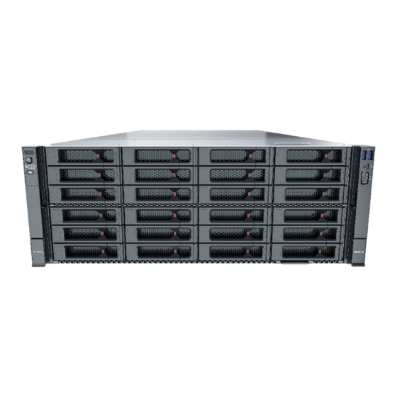
FusionServer G5500 V6 Server Technical White Paper 5 Hardware Description Hardware Description 5.1 Front Panel 5.2 Rear Panel 5.3 Processors 5.4 Memory 5.5 Storage 5.6 Network 5.7 I/O Expansion 5.8 PSUs 5.9 Fan Modules 5.10 Boards 5.1 Front Panel 5.1.1 Appearance ⚫... - Page 18 FusionServer G5500 V6 Server Technical White Paper 5 Hardware Description Figure 5-1 Front view SATA/SAS drives SAS/SATA/NVMe drives Slide-out label plate (with an SN label) ⚫ 24 x 3.5" drive configuration (16 x SAS/SATA + 8 x NVMe) Figure 5-2 Front view...
-
Page 19: Indicators And Buttons
FusionServer G5500 V6 Server Technical White Paper 5 Hardware Description 5.1.2 Indicators and Buttons Indicator and Button Positions ⚫ 24 x 3.5" drive configuration Figure 5-3 Indicators and buttons on the front panel Fault diagnosis LED Power button/indicator Health status indicator... - Page 20 FusionServer G5500 V6 Server Technical White Paper 5 Hardware Description Silkscreen Indicator and Description Button yellow. ⚫ Steady yellow: The device is in the standby state. Power button: ⚫ When the device is powered on, you can press this button to gracefully shut down the...
-
Page 21: Ports
FusionServer G5500 V6 Server Technical White Paper 5 Hardware Description Silkscreen Indicator and Description Button adapter is in position and has just been inserted. ⚫ Steady green: The OCP 3.0 network adapter is in position, and the power supply is normal. - Page 22 FusionServer G5500 V6 Server Technical White Paper 5 Hardware Description USB 3.0 ports iBMC direct connect management port VGA port Port Description Table 5-2 Ports on the front panel Note Name Type Number Description VGA port DB15 Used to connect a display terminal, such as a monitor or KVM.
-
Page 23: Rear Panel
FusionServer G5500 V6 Server Technical White Paper 5 Hardware Description Note Name Type Number Description NOTICE Before connecting an external ⚫ USB device, ensure that the USB device functions properly; otherwise, it may adversely impact the server. For details about how to ⚫... -
Page 24: Indicators And Buttons
FusionServer G5500 V6 Server Technical White Paper 5 Hardware Description Slot 12 (PCIe 4.0 x16) Slot 14 (PCIe 4.0 x16) Slot 16 (PCIe 4.0 x16) PSU 1 PSU 2 PSU 3 PSU 4 FlexIO card 3 Slot 21 (PCIe 4.0 x16) FlexIO card 2 Slot 20 (PCIe 4.0 x16) - Page 25 FusionServer G5500 V6 Server Technical White Paper 5 Hardware Description currently PSU indicator Indicator Description Table 5-3 Indicators on the rear panel Silkscreen Indicator Description Data transmission Off: No data is being transmitted. ⚫ status indicator for ⚫ Blinking yellow: Data is being the management transmitted.
-
Page 26: Ports
FusionServer G5500 V6 Server Technical White Paper 5 Hardware Description Silkscreen Indicator Description NOTE You can control the UID indicator status by pressing the UID button or using the iBMC. 5.2.3 Ports Port Positions Figure 5-7 Ports on the rear panel... -
Page 27: Processors
FusionServer G5500 V6 Server Technical White Paper 5 Hardware Description Name Type Quantity Description The management network port is a GE port that supports 100 Mbit/s and 1000 Mbit/s auto-negotiation. Serial port RJ45 A port used for debugging. By default, it serves as the OS serial port. -
Page 28: Memory
FusionServer G5500 V6 Server Technical White Paper 5 Hardware Description ⚫ Processors of the same model must be used in a server. ⚫ Consult your local sales representative or see "OS and Parts Compatibility" in the Compatibility Checker to determine the components to be used. - Page 29 FusionServer G5500 V6 Server Technical White Paper 5 Hardware Description Figure 5-9 Memory identifier Description Example Capacity ⚫ 16 GB 32 GB ⚫ ⚫ 64 GB ⚫ 128 GB ⚫ 256 GB rank(s) ⚫ 1R = Single rank 2R = Dual rank ⚫...
-
Page 30: Memory Subsystem Architecture
FusionServer G5500 V6 Server Technical White Paper 5 Hardware Description Description Example (NT): 0° C to 85° C (32° F to 185° F) 5.4.1.2 Memory Subsystem Architecture The server provides 32 memory interfaces. Each processor integrates eight memory channels. Install the memory modules in the primary memory channels first. If the primary memory channel is not populated, the memory modules in secondary memory channel cannot be used. -
Page 31: Memory Compatibility
FusionServer G5500 V6 Server Technical White Paper 5 Hardware Description Channel DIMM DIMM121(K) D (primary) DIMM130(D) DIMM131(L) E (primary) DIMM140(E) DIMM141(M) F (primary) DIMM150(F) DIMM151(N) G (primary) DIMM160(G) DIMM161(O) H (primary) DIMM170(H) DIMM171(P) 5.4.1.3 Memory Compatibility Observe the following rules when configuring DDR4 DIMMs: ⚫... -
Page 32: Dimm Installation Rules
FusionServer G5500 V6 Server Technical White Paper 5 Hardware Description ⚫ Each memory channel supports more than eight ranks for load-reduced DIMMs (LRDIMMs). A quad-rank LRDIMM generates the same electrical load as a single-rank RDIMM on a memory bus. Table 5-6 DDR4 DIMM specifications... -
Page 33: Memory Installation Positions
FusionServer G5500 V6 Server Technical White Paper 5 Hardware Description The capacity of a standby rank must be greater than or equal to that of other − ranks in the same channel. ⚫ Installation rules for the memory mirroring mode Comply with the general installation guidelines. - Page 34 FusionServer G5500 V6 Server Technical White Paper 5 Hardware Description Figure 5-10 Memory Installation Positions 2023-02-14...
- Page 35 FusionServer G5500 V6 Server Technical White Paper 5 Hardware Description Figure 5-11 DDR4 DIMM installation guidelines (1 processor) 2023-02-14...
- Page 36 FusionServer G5500 V6 Server Technical White Paper 5 Hardware Description Figure 5-12 DDR4 DIMM installation guidelines (2 processors) 2023-02-14...
-
Page 37: Memory Protection Technologies
FusionServer G5500 V6 Server Technical White Paper 5 Hardware Description 5.4.1.6 Memory Protection Technologies DDR4 DIMMs support the following memory protection technologies: ⚫ ⚫ Memory Mirroring ⚫ Memory Single Device Data Correction (SDDC) ⚫ Failed DIMM Isolation ⚫ Memory Thermal Throttling ⚫... - Page 38 RAID controller card. The drive numbers identified by the RAID controller card in this section are provided based on the default cabling described in "Internal Cabling" in the FusionServer G5500 V6 Server Maintenance and Service Guide. ⚫...
-
Page 39: 24 X 3.5" Drive Configuration (16 X Sas/Sata + 8 X Nvme)
FusionServer G5500 V6 Server Technical White Paper 5 Hardware Description Drive number Drive Number Displayed Drive Number Identified on the iBMC WebUI by the RAID Controller Card ⚫ a: SAS/SATA/NVMe drives are supported. 5.5.1.2 24 x 3.5" drive configuration (16 x SAS/SATA + 8 x NVMe) - Page 40 RAID controller card. The drive numbers identified by the RAID controller card in this section are provided based on the default cabling described in "Internal Cabling" in the FusionServer G5500 V6 Server Maintenance and Service Guide. ⚫...
- Page 41 FusionServer G5500 V6 Server Technical White Paper 5 Hardware Description Figure 5-14 Drive numbering Table 5-10 Drive numbering Drive number Drive Number Displayed Drive Number Identified by the RAID Controller on the iBMC WebUI Card 2023-02-14...
-
Page 42: Drive Indicators
FusionServer G5500 V6 Server Technical White Paper 5 Hardware Description Drive number Drive Number Displayed Drive Number Identified on the iBMC WebUI by the RAID Controller Card ⚫ a: SAS/SATA/NVMe drives are supported. 5.5.2 Drive Indicators SAS/SATA Drive Indicators Figure 5-15 SAS/SATA drive indicators... - Page 43 FusionServer G5500 V6 Server Technical White Paper 5 Hardware Description NVMe Drive Indicators Figure 5-16 NVMe drive indicators ⚫ If the VMD function is enabled and the latest VMD driver is installed, the NVMe drives support surprise hot swap. Table 5-12 NVMe drive indicators (VMD enabled)
-
Page 44: Raid Controller Card
FusionServer G5500 V6 Server Technical White Paper 5 Hardware Description Active Indicator Fault Indicator Description (Green) (Red/Blue) Blinking at 4 Hz Data is being read from or written to the NVMe drive. Steady on/Blinking Blinking blue at 4 The NVMe drive is being located. -
Page 45: Pcie Slots
FusionServer G5500 V6 Server Technical White Paper 5 Hardware Description ⚫ When IB cards are used to build an IB network, ensure that the IPoIB modes of the IB cards at both ends of the network are the same. For details, contact technical support. - Page 46 FusionServer G5500 V6 Server Technical White Paper 5 Hardware Description Figure 5-18 PCIe slot ⚫ I/O module 1 provides slots 18, 19, 20, and 21. Configure the number of PCIe riser cards based on the number of NICs. ⚫ I/O module 2 provides slot 26 and supports a built-in PCIe card.
-
Page 47: Pcie Slot Description
FusionServer G5500 V6 Server Technical White Paper 5 Hardware Description Figure 5-20 PCIe riser card 5.7.3 PCIe Slot Description Server PCIe Slot Information When CPU 2 is not detected, the corresponding PCIe slot is unavailable. Table 5-14 PCIe slot description... - Page 48 FusionServer G5500 V6 Server Technical White Paper 5 Hardware Description PCIe PCIe PCIe Slot PCIe Switch PCIe Riser Slot or Port Port No. Device Card Descripti Supporte d by the PCIe Slot or Port Slot 14 PCIe 4.0 CPU2 PE 3...
-
Page 49: Psus
FusionServer G5500 V6 Server Technical White Paper 5 Hardware Description Server Bus/Device/Function Number (B/D/F) Information The server's B/D/F information may change with PCIe card configurations. You can obtain the B/D/F information of the server using the following methods: ⚫ BIOS serial port log: If the serial port log has been collected, you can query the B/D/F information of the server by searching for the keyword RootBusBDF. -
Page 50: Fan Modules
FusionServer G5500 V6 Server Technical White Paper 5 Hardware Description Figure 5-21 Positions of PSUs 5.9 Fan Modules ⚫ The server supports four fan modules. ⚫ The fan modules are hot-swappable. ⚫ N+1 redundancy is supported. That is, the server can work properly when a single fan fails. - Page 51 FusionServer G5500 V6 Server Technical White Paper 5 Hardware Description Figure 5-22 Positions of fan modules 2023-02-14...
-
Page 52: Boards
FusionServer G5500 V6 Server Technical White Paper 5 Hardware Description 5.10 Boards 5.10.1 Mainboard Figure 5-23 Mainboard OCP 3.0 network adapter 3 OCP 3.0 network adapter 3 UBC connector connector (OCP3 (UBC2-3/J6054) CONN/J7023) 2023-02-14... - Page 53 FusionServer G5500 V6 Server Technical White Paper 5 Hardware Description RAID controller card OCP 3.0 network adapter 2 low-speed signal connector UBC connector (RAID MIS/J7017) (UBC2-2B/J6071) OCP 3.0 network adapter 2 Rear I/O board low-speed connector (OCP2 signal connector (BACK IO...
-
Page 54: Drive Backplane
FusionServer G5500 V6 Server Technical White Paper 5 Hardware Description connector (FAN connector (FAN PWR_2/J7006) PWR_1/J7010) PSU backplane input power Copper bar power connector (PWR IN/J6093) connector (PWR GND/J7008) Copper bar power PSU backplane power connector (PWR connector (PDB MIS... - Page 55 FusionServer G5500 V6 Server Technical White Paper 5 Hardware Description MAINBOARD/J42) UBC 3 high-speed UBC 2 high-speed connector (J4) connector (J3) Low-speed signal Power connector (POWER connector (REAR BP/J39) REAR BP/J43) UBC 1 high-speed connector (J2) Figure 5-25 24 x 3.5" drive EXP backplane 2 (16 x SAS/SATA + 8 x NVMe) The backplane is supported by all drive configurations in section 5.5.1.2 24 x 3.5"...
-
Page 56: Fan Board
FusionServer G5500 V6 Server Technical White Paper 5 Hardware Description UBC 1 high-speed connector (J2) 5.10.3 Fan Board Figure 5-26 Fan board LAAC JTAG connector Fan board signal connector (LAAC JTAG/J17) (MISC CONN/J3) Water detection cable LAAC connector presence detection... -
Page 57: Psu Backplane
FusionServer G5500 V6 Server Technical White Paper 5 Hardware Description Fan connector Fan connector (FAN4B/J12) (FAN4A/J10) a: Reserved and unavailable currently 5.10.4 PSU Backplane Figure 5-27 PSU backplane Power connector (HDD Power connector (RSW-2& BP/J100) MB/J102) Power connector Guide sleeve (J108) (RSW-1&RISER/J101) -
Page 58: Pcie Switch Board
FusionServer G5500 V6 Server Technical White Paper 5 Hardware Description 5.10.5 PCIe Switch Board Figure 5-28 PCIe switch board CEM connector (PCIE CEM connector (PCIE SLOT16 X16/J18) SLOT14 X16/J17) CEM connector (PCIE CEM connector (PCIE SLOT12 X16/J16) SLOT10 X16/J15) Power connector (PWR... - Page 59 FusionServer G5500 V6 Server Technical White Paper 5 Hardware Description UBC high-speed connector UBC high-speed connector (UBC1-5B/J137) (UBC1-5A/J136) UBC high-speed connector GPU power connector (UBC6-HDDBP/J140) (GPU PWR CONN1/J111) GPU power connector GPU power connector (GPU PWR CONN3/J112) (GPU PWR CONN5/J113)
-
Page 60: Ssd Adapter Board
FusionServer G5500 V6 Server Technical White Paper 5 Hardware Description 5.10.6 M.2 SSD Adapter Board Figure 5-29 M.2 SSD adapter board Signal connector (J1) High-speed connector (J2) 2023-02-14... -
Page 61: Product Specifications
FusionServer G5500 V6 Server Technical White Paper 6 Product Specifications Product Specifications 6.1 Technical Specifications 6.2 Environmental Specifications 6.3 Physical Specifications 6.1 Technical Specifications Table 6-1 Technical specifications Category Specifications Form factor 4U GPU server ® Chipset Intel C621A Processors Supports one or two processors. - Page 62 FusionServer G5500 V6 Server Technical White Paper 6 Product Specifications Category Specifications RDIMM or RDIMM-3DS supported − − Max. 3200 MT/s memory speed The DDR4 DIMMs of different types (RDIMM and − LRDIMM) and specifications (capacity, bit width, rank, and height) cannot be used together.
- Page 63 FusionServer G5500 V6 Server Technical White Paper 6 Product Specifications Category Specifications Supports hot swap of SAS/SATA/NVMe U.2 drives. ⚫ NOTE When NVMe drives are configured, note the following: Before using the VMD function, contact technical support ⚫ engineers of the OS vendor to check whether the OS supports the VMD function.
- Page 64 FusionServer G5500 V6 Server Technical White Paper 6 Product Specifications Category Specifications Port Supports a variety of ports. ⚫ Ports on the front panel: − One USB Type-C iBMC direct connect management port Two USB 3.0 ports − One DB15 VGA port −...
-
Page 65: Environmental Specifications
FusionServer G5500 V6 Server Technical White Paper 6 Product Specifications 6.2 Environmental Specifications Table 6-2 Environmental specifications Category Specifications Temperature ⚫ Operating temperature: 5° C to 35° C (41° F to 95 ° F) (ASHRAE Classes A1 to A4 compliant) Storage temperature (within three months): –30°... -
Page 66: Physical Specifications
FusionServer G5500 V6 Server Technical White Paper 6 Product Specifications Category Specifications Particle contaminant ⚫ The equipment room environment meets the requirements of ISO 14664-1 Class 8. There is no explosive, conductive, magnetic, or ⚫ corrosive dust in the equipment room. - Page 67 FusionServer G5500 V6 Server Technical White Paper 6 Product Specifications Category Description Figure 6-1 Physical dimensions (example: 3.5" drive chassis) NOTE ⚫ See Figure 6-1 for methods in measuring physical dimensions of the chassis. Installation dimension ⚫ Requirements for cabinet installation:...
- Page 68 FusionServer G5500 V6 Server Technical White Paper 6 Product Specifications Category Description Power Calculator to obtain specific information. 2023-02-14...
-
Page 69: Software And Hardware Compatibility
FusionServer G5500 V6 Server Technical White Paper 7 Software and Hardware Compatibility Software and Hardware Compatibility For details about the information of the OSs and hardware, see the Compatibility Checker. ⚫ If incompatible components are used, the device may be abnormal. Such a fault is beyond the scope of technical support and warranty. -
Page 70: Safety Instructions
FusionServer G5500 V6 Server Technical White Paper 8 Safety Instructions Safety Instructions 8.1 Security 8.2 Maintenance and Warranty 8.1 Security General Statement ⚫ Comply with local laws and regulations when operating devices. These safety instructions are only a supplement. ⚫... - Page 71 FusionServer G5500 V6 Server Technical White Paper 8 Safety Instructions ⚫ Wear clean protective gloves, ESD clothing, a protective hat, and protective shoes, as shown in Figure 8-1. Figure 8-1 Protective clothing ⚫ Before touching a device, wear ESD clothing and gloves (or wrist strap), and remove conductive objects (such as watches and jewelry).
- Page 72 FusionServer G5500 V6 Server Technical White Paper 8 Safety Instructions Figure 8-3 Wearing an ESD wrist strap ⚫ Exercise caution when using tools. ⚫ If the installation position of a device is higher than the shoulders of the installation personnel, use a vehicle such as a lift to facilitate installation. Prevent the device from falling down and causing personal injury or damage to the device.
-
Page 73: Maintenance And Warranty
FusionServer G5500 V6 Server Technical White Paper 8 Safety Instructions device being transported is always kept upright. Take necessary precautions to prevent collisions, corrosion, package damage, damp conditions, and pollution. ⚫ Transport each device in its original packaging. ⚫ If the original packaging is unavailable, package heavy, bulky parts (such as chassis and blades) and fragile parts (such as PCIe cards and optical modules) separately. -
Page 74: System Management
FusionServer G5500 V6 Server Technical White Paper 9 System Management System Management The server the new-generation iBMC, which complies with Intelligent Platform Management Interface 2.0 (IPMI 2.0) specifications and provides highly reliable hardware monitoring and management. The iBMC supports the following features and protocols: ⚫... - Page 75 FusionServer G5500 V6 Server Technical White Paper 9 System Management ⚫ System maintenance interface The virtual KVM and virtual media functions facilitate remote maintenance. − Out-of-band RAID monitoring and configuration are supported to improve − RAID configuration efficiency and management capability.
-
Page 76: Certifications
FusionServer G5500 V6 Server Technical White Paper 10 Certifications Certifications Country/Region Certification Standard China GB4943.1-2011 GB9254-2008(Class A) GB17625.1-2012 2023-02-14... -
Page 77: A Appendix
FusionServer G5500 V6 Server Technical White Paper A Appendix Appendix A.1 Chassis Label Information A.1.1 Chassis Head Label A.1.1.1 Nameplate Figure A-1 Nameplate example Table A-1 Nameplate description Description Server model For details, see A.4 Nameplate. Device name Power supply requirements... - Page 78 FusionServer G5500 V6 Server Technical White Paper A Appendix A.1.1.2 Certificate Figure A-2 Certificate example Table A-2 Certificate description Description Order NOTE For details, see Figure A-3 and Table A-3. QC inspector Production date No. barcode Figure A-3 Certificate number example...
- Page 79 FusionServer G5500 V6 Server Technical White Paper A Appendix Description B: a semi-finished server ⚫ ⚫ N: a spare part 0: a value for the reserved digit Year (two characters) Month (one character) Digits 1 to 9 indicate January to September respectively.
- Page 80 FusionServer G5500 V6 Server Technical White Paper A Appendix Description Subnet mask of the default iBMC management network port Default iBMC username Default iBMC password Default BIOS password Technical support website P/N code QR code NOTE Scan the QR code to obtain technical support resources.
- Page 81 FusionServer G5500 V6 Server Technical White Paper A Appendix A.1.3 Chassis Tail Label Figure A-6 Chassis tail label For details about the warning labels, see the Server Security Information. A.2 SN The serial number (SN) on the slide-out label plate uniquely identifies a device. The SN is required when you contact technical support.
- Page 82 FusionServer G5500 V6 Server Technical White Paper A Appendix Description 2009, respectively. − Letters A to H indicate years 2010 to 2017, respectively. Letters J to N indicate years 2018 − to 2022, respectively. − Letters P to Y indicate years 2023 to 2032, respectively.
- Page 83 FusionServer G5500 V6 Server Technical White Paper A Appendix A.4 Nameplate Certified Model Remarks G5500 V6 Global A.5 RAS Features The server supports a variety of Reliability, Availability, and Serviceability (RAS) features. You can configure these features for better performance.
- Page 84 FusionServer G5500 V6 Server Technical White Paper A Appendix Sensor Description Component Riser 12V 12 V voltage supplied by Mainboard the mainboard to the riser card SYS 3.3V Mainboard 3.3 V voltage Mainboard CPUN DDR VDDQ 1.2 V DIMM voltage...
- Page 85 FusionServer G5500 V6 Server Technical White Paper A Appendix Sensor Description Component value ranges from 1 to 4. Power Server input power PS$ VIN Input voltage Disks Temp Maximum drive Drive temperature SSD Disk$ Temp SSD temperature SSD MaxTemp Maximum SSD...
- Page 86 FusionServer G5500 V6 Server Technical White Paper A Appendix Sensor Description Component Power Button Power button pressed Mainboard and power state button Watchdog2 Watchdog Mainboard Mngmnt Health Management subsystem Management module health status UID Button UID button status Mainboard PwrOk Sig. Drop...
- Page 87 FusionServer G5500 V6 Server Technical White Paper A Appendix Sensor Description Component number of the drive. The value ranges from 0 to 23. PCIe RAID$ Temp Temperature of the PCIe PCIe RAID controller card RAID controller card PCIe$ OP Temp...
- Page 88 FusionServer G5500 V6 Server Technical White Paper A Appendix Sensor Description Component the NPU card NPU$ Inlet Temp Air inlet temperature of NPU card the NPU card NPU$ VRD Temp VRD temperature of the NPU card NPU card LCD Status...
- Page 89 FusionServer G5500 V6 Server Technical White Paper A Appendix Sensor Description Component Sec. Log Full Security log full or events being cleared Host Loss System monitoring software (BMA) link loss detection A.7 FAQs About Optical Modules The server NIC must be used with optical modules that have passed the compatibility test of xFusion.
- Page 90 FusionServer G5500 V6 Server Technical White Paper A Appendix Symptom Cause monitoring causes incorrect modules that have not been tested for compatibility alarms. do not comply with industry standards and report temperature values higher than the real temperature. When such optical modules are used, the system will report incorrect temperature alarms.
-
Page 91: B Glossary
FusionServer G5500 V6 Server Technical White Paper B Glossary Glossary B.1 A-E baseboard management controller The BMC complies with the Intelligent (BMC) Platform Management Interface (IPMI). It collects, processes, and stores sensor signals, and monitors the operating status of components. The BMC... - Page 92 FusionServer G5500 V6 Server Technical White Paper B Glossary B.2 F-J Gigabit Ethernet (GE) An extension and enhancement of traditional shared media Ethernet standards. It is compatible with 10 Mbit/s and 100 Mbit/s Ethernet and complies with IEEE 802.3z standards.
- Page 93 FusionServer G5500 V6 Server Technical White Paper B Glossary and PCI). redundancy A mechanism that allows a backup device to automatically take over services from a faulty device to ensure uninterrupted running of the system. redundant array of independent disks...
-
Page 94: C Acronyms And Abbreviations
FusionServer G5500 V6 Server Technical White Paper C Acronyms and Abbreviations Acronyms and Abbreviations C.1 A-E alternating current Advanced Encryption Standard New Instruction Set Address Resolution Protocol Advanced Vector Extensions backup battery unit BIOS Basic Input/Output System Baseboard Management Controller... - Page 95 FusionServer G5500 V6 Server Technical White Paper C Acronyms and Abbreviations direct current DDR4 Double Data Rate 4 DDDC double device data correction DEMT Dynamic Energy Management Technology DIMM dual in-line memory module DRAM dynamic random-access memory digital video disc...
- Page 96 FusionServer G5500 V6 Server Technical White Paper C Acronyms and Abbreviations GPIO General Purpose Input/Output graphics processing unit high availability hard disk drive high-performance computing HTTP Hypertext Transfer Protocol HTTPS Hypertext Transfer Protocol Secure iBMC Intelligent Baseboard Management Controller Industry Canada...
- Page 97 FusionServer G5500 V6 Server Technical White Paper C Acronyms and Abbreviations Lucent connector LRDIMM load-reduced dual in-line memory module light emitting diode LAN on motherboard media access control module management controller next business day NC-SI Network Controller Sideband Interface Open Compute Project C.4 P-T...
- Page 98 FusionServer G5500 V6 Server Technical White Paper C Acronyms and Abbreviations RAID redundant array of independent disks reliability, availability and serviceability RDIMM registered dual in-line memory module REACH Registration Evaluation and Authorization of Chemicals RJ45 registered jack 45 RoHS Restriction of the Use of Certain...
- Page 99 FusionServer G5500 V6 Server Technical White Paper C Acronyms and Abbreviations Turbo Boost Technology Trusted Computing Group trusted cryptography module total cost of ownership thermal design power TELNET Telecommunication Network Protocol Trusted Execution Technology TransFlash module TFTP Trivial File Transfer Protocol...
- Page 100 FusionServer G5500 V6 Server Technical White Paper C Acronyms and Abbreviations WEEE Waste Electrical and Electronic Equipment WSMAN Web Service Management 2023-02-14...
Need help?
Do you have a question about the FusionServer G5500 V6 and is the answer not in the manual?
Questions and answers