
Related Manuals for xFusion Digital Technologies FusionServer 1288H V6


Summary of Contents for xFusion Digital Technologies FusionServer 1288H V6
- Page 1 FusionServer 1288H V6 Server Technical White Paper Issue Date 2023-04-30 xFusion Digital Technologies Co., Ltd.
- Page 2 Notice In this document, "xFusion" is used to refer to "xFusion Digital Technologies Co., Ltd." for concise description and easy understanding, which does not mean that "xFusion" may have any other meaning. Any "xFusion" mentioned or described hereof may not be understood as any meaning other than "xFusion Digital Technologies Co., Ltd.", and xFusion Digital Technologies Co., Ltd.
-
Page 3: About This Document
Technical White Paper About This Document About This Document Purpose This document describes the FusionServer 1288H V6 rack server in terms of features, structure, specifications, and component hardware and software compatibility. Intended Audience This document is intended for pre-sales engineers. - Page 4 5.4.2 PMem. 2022-03-18 ● Added Certifications. ● Updated 5.4.1.6 Memory Protection Technologies. ● Updated 6.1 Technical Specifications claimed support for U.2 drives. 2021-12-24 This issue is the first official release. Issue 10 (2023-04-30) Copyright © xFusion Digital Technologies Co., Ltd.
-
Page 5: Table Of Contents
5.4.2 PMem..............................30 5.4.2.1 Memory Identifier..........................30 5.4.2.2 Memory Subsystem Architecture......................31 5.4.2.3 Memory Compatibility.......................... 32 5.4.2.4 DIMM Installation Rules........................33 5.4.2.5 Memory Installation Positions......................34 5.4.2.6 Memory Protection Technologies......................35 5.5 Storage..............................36 Issue 10 (2023-04-30) Copyright © xFusion Digital Technologies Co., Ltd. - Page 6 A.1.2 Chassis Tail Label...........................82 A.1.3 Chassis Internal Label..........................82 A.2 Product SN..............................82 A.3 Operating Temperature Limitations......................84 A.4 Nameplate..............................91 A.5 RAS Features............................91 A.6 Sensor List..............................91 B Glossary......................... 99 B.1 A-E................................99 Issue 10 (2023-04-30) Copyright © xFusion Digital Technologies Co., Ltd.
- Page 7 Technical White Paper Contents B.2 F-J................................100 B.3 K-O................................100 B.4 P-T................................100 B.5 U-Z................................101 C Acronyms and Abbreviations..................102 C.1 A-E................................102 C.2 F-J................................103 C.3 K-O................................104 C.4 P-T................................105 C.5 U-Z................................107 Issue 10 (2023-04-30) Copyright © xFusion Digital Technologies Co., Ltd.
-
Page 8: Overview
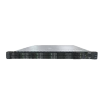
Technical White Paper 1 Overview Overview FusionServer 1288H V6 (1288H V6) is a new-generation 1U 2-socket rack server designed for Internet, Internet Data Center (IDC), cloud computing, enterprise, and telecom applications. The 1288H V6 is ideal for IT core services, cloud computing, virtualization, high- performance computing, distributed storage, big data processing, enterprise or telecom service applications, and other complex workloads. -
Page 9: Features
400 GB/s in theory. ® – The server supports a maximum of 16 Intel Optane Persistent Memory Module 200 series (PMem modules for short), which must be used with the Issue 10 (2023-04-30) Copyright © xFusion Digital Technologies Co., Ltd. - Page 10 Manageability and Security ● The built-in iBMC monitors server operating status and provides remote management. ● A password is required for accessing the BIOS, ensuring system boot and management security. Issue 10 (2023-04-30) Copyright © xFusion Digital Technologies Co., Ltd.
- Page 11 Efficient voltage regulator-down (VRD) power supplies for boards minimize the energy loss from DC/DC power conversion. ● Area-based, Proportional-Integral-Derivative (PID) intelligent fan speed adjustment and intelligent CPU frequency scaling optimize heat dissipation and reduce overall system power consumption. Issue 10 (2023-04-30) Copyright © xFusion Digital Technologies Co., Ltd.
- Page 12 The improved thermal design with energy-efficient fans ensures optimal heat dissipation and reduces system power consumption. ● The server is protected with power capping and power control measures. ● Staggered spin-up of drives reduces the server boot power consumption. Issue 10 (2023-04-30) Copyright © xFusion Digital Technologies Co., Ltd.
-
Page 13: Physical Structure
I/O module 2 Chassis PSUs Air duct Fan module brackets Fan modules Intrusion sensor Front-drive backplane Front drives Built-in DVD drive Indicator board Processor heat sinks Processors Cable organizers Mainboard Issue 10 (2023-04-30) Copyright © xFusion Digital Technologies Co., Ltd. - Page 14 FusionServer 1288H V6 Server Technical White Paper 3 Physical Structure BMC card OCP 3.0 network adapters Screw-in RAID controller TPM/TCM card Memory modules Issue 10 (2023-04-30) Copyright © xFusion Digital Technologies Co., Ltd.
-
Page 15: Logical Structure
The screw-in RAID controller card on the mainboard connects to CPU 1 through PCIe buses, and connects to the drive backplane through SAS high-speed cables. A variety of drive backplanes are provided to support different local storage configurations. Issue 10 (2023-04-30) Copyright © xFusion Digital Technologies Co., Ltd. - Page 16 USB 3.0 ports. ● The BMC management chip integrated on the mainboard supports ports such as a video graphic array (VGA) port, a management network port, and a serial port. Issue 10 (2023-04-30) Copyright © xFusion Digital Technologies Co., Ltd.
-
Page 17: Hardware Description
5.8 PSUs 5.9 Fan Modules 5.10 Boards 5.1 Front Panel 5.1.1 Appearance ● 4 x 3.5" drive configuration Figure 5-1 Front view Drive Slide-out label plate (with an SN label) Issue 10 (2023-04-30) Copyright © xFusion Digital Technologies Co., Ltd. -
Page 18: Indicators And Buttons
4 x 3.5" drive configuration Figure 5-4 Indicators and buttons on the front panel Fault diagnosis LED Health status indicator FlexIO card 1 presence FlexIO card 2 presence indicator indicator Power button/indicator UID button/indicator Issue 10 (2023-04-30) Copyright © xFusion Digital Technologies Co., Ltd. - Page 19 Figure 5-6 Indicators and buttons on the front panel Fault diagnosis LED Health status indicator FlexIO card 1 presence FlexIO card 2 presence indicator indicator Power button/indicator iBMC direct connect management port indicator UID button/indicator Issue 10 (2023-04-30) Copyright © xFusion Digital Technologies Co., Ltd.
- Page 20 ● Blinking green at 2 Hz: The FlexIO card is detected and has just been inserted. ● Steady green: The FlexIO card is detected and the power supply is normal. Issue 10 (2023-04-30) Copyright © xFusion Digital Technologies Co., Ltd.
- Page 21 ● You can press this button to turn on or off the UID indicator. ● You can press and hold down this button for 4 to 6 seconds to reset the iBMC. Issue 10 (2023-04-30) Copyright © xFusion Digital Technologies Co., Ltd.
-
Page 22: Ports
Port Positions ● 4 x 3.5" drive configuration Figure 5-7 Ports on the front panel iBMC direct connect USB 3.0 port management port VGA port ● 8 x 2.5" drive configuration Issue 10 (2023-04-30) Copyright © xFusion Digital Technologies Co., Ltd. - Page 23 Port Description Table 5-2 Ports on the front panel Port Type Note Description Quantity VGA port DB15 Used to connect a display terminal, such as a monitor or KVM. Issue 10 (2023-04-30) Copyright © xFusion Digital Technologies Co., Ltd.
-
Page 24: Rear Panel
CD/DVD drives, an external power supply is required. Note: The number of ports varies depending on server configuration. This table lists the maximum number of ports in different configurations. 5.2 Rear Panel Issue 10 (2023-04-30) Copyright © xFusion Digital Technologies Co., Ltd. -
Page 25: Appearance
5.2.2 Indicators and Buttons Indicator Positions Figure 5-11 Indicators on the rear panel Data transmission status Connection status indicator indicator for the for the management management network port network port Issue 10 (2023-04-30) Copyright © xFusion Digital Technologies Co., Ltd. - Page 26 The possible causes of no power output are as follows: ● Power supply overtemperature protection ● Power output overcurrent or short- circuit ● Output overvoltage ● Short-circuit protection ● Device failure (excluding failure of all devices) Issue 10 (2023-04-30) Copyright © xFusion Digital Technologies Co., Ltd.
-
Page 27: Ports
NOTE The management network port is a GE port that supports 100 Mbit/s and 1000 Mbit/s auto-negotiation. Issue 10 (2023-04-30) Copyright © xFusion Digital Technologies Co., Ltd. -
Page 28: Processors
The server supports one or two processors. ● If only one processor is required, install it in socket CPU1. ● Processors of the same model must be used in a server. Issue 10 (2023-04-30) Copyright © xFusion Digital Technologies Co., Ltd. -
Page 29: Memory
Figure 5-13 Processor positions 5.4 Memory 5.4.1 DDR4 Memory 5.4.1.1 Memory ID You can determine the memory module properties based on the label attached to the memory module. Figure 5-14 Memory identifier Issue 10 (2023-04-30) Copyright © xFusion Digital Technologies Co., Ltd. -
Page 30: Memory Subsystem Architecture
Table 5-5 Memory channels Channel Memory Slot CPU 1 A (primary) DIMM000(A) DIMM001(I) B (primary) DIMM010(B) DIMM011(J) C (primary) DIMM020(C) Issue 10 (2023-04-30) Copyright © xFusion Digital Technologies Co., Ltd. -
Page 31: Memory Compatibility
DIMM130(D) DIMM131(L) E (primary) DIMM140(E) DIMM141(M) F (primary) DIMM150(F) DIMM151(N) G (primary) DIMM160(G) DIMM161(O) H (primary) DIMM170(H) DIMM171(P) 5.4.1.3 Memory Compatibility Observe the following rules when configuring DDR4 memory modules: Issue 10 (2023-04-30) Copyright © xFusion Digital Technologies Co., Ltd. - Page 32 A quad-rank LRDIMM generates the same electrical load as a single-rank RDIMM on a memory bus. Table 5-6 DDR4 memory specifications Parameter Specifications Capacity per DDR4 memory module (GB) Type RDIMM RDIMM RDIMM LRDIMM RDIMM Issue 10 (2023-04-30) Copyright © xFusion Digital Technologies Co., Ltd.
-
Page 33: Dimm Installation Rules
The capacity of a standby rank must be greater than or equal to that of other ranks in the same channel. ● Memory mirroring mode – Comply with the general installation guidelines. Issue 10 (2023-04-30) Copyright © xFusion Digital Technologies Co., Ltd. -
Page 34: Memory Installation Positions
For details, see Memory Configuration Assistant. NO TICE At least one DDR4 memory module must be installed in the primary memory channels corresponding to CPU 1. Figure 5-15 Memory slots Issue 10 (2023-04-30) Copyright © xFusion Digital Technologies Co., Ltd. - Page 35 FusionServer 1288H V6 Server Technical White Paper 5 Hardware Description Figure 5-16 DDR4 memory module installation guidelines (1 processor) Issue 10 (2023-04-30) Copyright © xFusion Digital Technologies Co., Ltd.
- Page 36 FusionServer 1288H V6 Server Technical White Paper 5 Hardware Description Figure 5-17 DDR4 memory module installation guidelines (2 processors) Issue 10 (2023-04-30) Copyright © xFusion Digital Technologies Co., Ltd.
-
Page 37: Memory Protection Technologies
Adaptive Double Device Data Correction - Multiple Region (ADDDC-MR) ● Partial Cache Line Sparing (PCLS) 5.4.2 PMem 5.4.2.1 Memory Identifier Figure 5-18 Memory identifier Description Example Component Intel Optane Persistent Memory Issue 10 (2023-04-30) Copyright © xFusion Digital Technologies Co., Ltd. -
Page 38: Memory Subsystem Architecture
DIMM010(B) DIMM011(J) C (primary) DIMM020(C) DIMM021(K) D (primary) DIMM030(D) DIMM031(L) E (primary) DIMM040(E) DIMM041(M) F (primary) DIMM050(F) DIMM051(N) G (primary) DIMM060(G) DIMM061(O) H (primary) DIMM070(H) DIMM071(P) CPU2 A (primary) DIMM100(A) Issue 10 (2023-04-30) Copyright © xFusion Digital Technologies Co., Ltd. -
Page 39: Memory Compatibility
(MM). The total supported memory capacity is calculated as follows: – PMem module in AD mode Total memory capacity = Total capacity of all PMem modules+ Total capacity of all DDR4 memory modules – PMem module in MM mode Issue 10 (2023-04-30) Copyright © xFusion Digital Technologies Co., Ltd. -
Page 40: Dimm Installation Rules
● The information listed in this table is for reference only. For details, consult the local sales representative. 5.4.2.4 DIMM Installation Rules ● Observe the following when configuring PMem modules: Issue 10 (2023-04-30) Copyright © xFusion Digital Technologies Co., Ltd. -
Page 41: Memory Installation Positions
A server supports a maximum of 16 PMem modules. The PMem modules must be used with the DDR4 memory modules. Observe the memory module installation rules when configuring memory modules. For details, see Memory Configuration Assistant. Figure 5-19 Memory slots Issue 10 (2023-04-30) Copyright © xFusion Digital Technologies Co., Ltd. -
Page 42: Memory Protection Technologies
5 Hardware Description Figure 5-20 PMem module installation guidelines (1 processor) Figure 5-21 PMem module installation guidelines (2 processors) 5.4.2.6 Memory Protection Technologies The following memory protection technologies are supported: Issue 10 (2023-04-30) Copyright © xFusion Digital Technologies Co., Ltd. -
Page 43: Storage
SATA drives. 4 x 3.5" drive ● Front drive: 4 x ● 1 x PCIe RAID pass-through controller card configuration 3 – Slots 0 to 3 support only SAS/SATA drives. Issue 10 (2023-04-30) Copyright © xFusion Digital Technologies Co., Ltd. - Page 44 SATA drives. 10 x 2.5" drive ● Front drive: 10 ● 1 x PCIe RAID pass-through x 2.5" controller card configuration 2 – Slots 0 to 9 support only SAS/SATA drives. Issue 10 (2023-04-30) Copyright © xFusion Digital Technologies Co., Ltd.
- Page 45 – Slots 0 to 5 card support only SAS/SATA ● NVMe drive: drives. – Slots 6 and 7 support SAS/SATA/ NVMe drives. – Slots 8 and 9 support only NVMe drives. Issue 10 (2023-04-30) Copyright © xFusion Digital Technologies Co., Ltd.
-
Page 46: Drive Numbering
RAID controller card. The drive numbers identified by the RAID controller card in this section are provided based on the default cabling described in "Internal Cabling" in FusionServer 1288H V6 Server Maintenance and Service Guide. Issue 10 (2023-04-30) Copyright © xFusion Digital Technologies Co., Ltd. - Page 47 Corresponds to 4 x 3.5" drive pass-through configuration 2 in 5.5.1 Drive Configurations. Figure 5-23 Slot Numbers Table 5-11 Slot numbers Drive No. Drive Number Drive Number Identified by the iBMC Identified by the RAID Controller Issue 10 (2023-04-30) Copyright © xFusion Digital Technologies Co., Ltd.
- Page 48 8 x 2.5" drive pass-through configuration Corresponds to 8 x 2.5" drive pass-through configuration 1 in 5.5.1 Drive Configurations. Figure 5-25 Slot numbers Table 5-13 Slot numbers Drive No. Drive Number Identified by the iBMC Issue 10 (2023-04-30) Copyright © xFusion Digital Technologies Co., Ltd.
- Page 49 Corresponds to 10 x 2.5" drive pass-through configuration 1 in 5.5.1 Drive Configurations. Figure 5-27 Slot numbers Table 5-15 Slot numbers Drive No. Drive Number Drive Number Identified by the iBMC Identified by the RAID Controller Issue 10 (2023-04-30) Copyright © xFusion Digital Technologies Co., Ltd.
- Page 50 Corresponds to 10 x 2.5" drive pass-through configuration 2 in 5.5.1 Drive Configurations. Figure 5-28 Slot numbers Table 5-16 Slot numbers Drive No. Drive Number Drive Number Identified by the iBMC Identified by the RAID Controller Issue 10 (2023-04-30) Copyright © xFusion Digital Technologies Co., Ltd.
- Page 51 10 x 2.5" drive pass-through configuration Corresponds to 10 x 2.5" drive pass-through configuration 4 and 10 x 2.5" drive pass-through configuration 5 in 5.5.1 Drive Configurations. Figure 5-30 Slot Numbers Issue 10 (2023-04-30) Copyright © xFusion Digital Technologies Co., Ltd.
- Page 52 10 x 2.5" NVMe drive configuration Corresponds to 10 x 2.5" drive NVMe configuration 1 in 5.5.1 Drive Configurations. Figure 5-31 Slot Numbers Table 5-19 Slot numbers Drive No. Drive Number Identified by the iBMC Issue 10 (2023-04-30) Copyright © xFusion Digital Technologies Co., Ltd.
- Page 53 Controller Note Note Note Note Note: If the slot is configured with a SAS/SATA drive, the RAID controller card can manage the drive and allocate a number to the drive. Issue 10 (2023-04-30) Copyright © xFusion Digital Technologies Co., Ltd.
-
Page 54: Drive Indicators
The drive is faulty. NVMe Drive Indicators Figure 5-34 NVMe drive indicators ● If the VMD function is enabled and the latest VMD driver is installed, the NVMe drives support surprise hot swap. Issue 10 (2023-04-30) Copyright © xFusion Digital Technologies Co., Ltd. - Page 55 Steady on/Off Steady on The NVMe drive is faulty. M.2 FRU Indicators The server supports the Avago SAS3004iMR RAID controller card, which supports two M.2 FRUs. Issue 10 (2023-04-30) Copyright © xFusion Digital Technologies Co., Ltd.
-
Page 56: Raid Controller Card
5.6 Network 5.6.1 OCP 3.0 Network Adapter OCP 3.0 network adapters provide network expansion capabilities. ● The FlexIO slot supports the OCP 3.0 network adapter, which can be configured as required. Issue 10 (2023-04-30) Copyright © xFusion Digital Technologies Co., Ltd. -
Page 57: I/O Expansion
I/O module 1 provides slots 1 and 2. ● I/O module 2 provides slot 3. PCIe Riser Modules ● PCIe riser module 1 Provides PCIe slots 1 and 2 in I/O module 1. Issue 10 (2023-04-30) Copyright © xFusion Digital Technologies Co., Ltd. -
Page 58: Pcie Slot Description
Provides PCIe slot 3 in I/O module 2. Figure 5-38 PCIe riser module 5.7.3 PCIe Slot Description NO TE The PCIe slots mapping to a vacant CPU socket are unavailable. Issue 10 (2023-04-30) Copyright © xFusion Digital Technologies Co., Ltd. - Page 59 Slot1 CPU1 PCIe Port1A 30/02/ 31/00/ FHHL Slot2 CPU1 PCIe Port2A HHHL 02/0 00/0 Slot3 CPU2 PCIe Port0A 97/02/ 98/00/ HHHL Issue 10 (2023-04-30) Copyright © xFusion Digital Technologies Co., Ltd.
-
Page 60: Psus
DC power supply that has passed the CCC certification. ● Contact your local sales representative or see "Search Parts" in the Compatibility Checker to determine the components to be used. Figure 5-39 Positions of PSUs Issue 10 (2023-04-30) Copyright © xFusion Digital Technologies Co., Ltd. -
Page 61: Fan Modules
● The fan speed can be adjusted. ● Fan modules of the same P/N code must be used in a server. Figure 5-40 Positions of fan modules 5.10 Boards Issue 10 (2023-04-30) Copyright © xFusion Digital Technologies Co., Ltd. -
Page 62: Mainboard
OCP 3.0 network adapter 2 CARD/J86) (SLIMLINE7/J31) OCP 3.0 network adapter 2 Built-in storage expansion connector (OCP2 CONN/ port (SD CARD/J87) J109) 2 x USB 3.0 ports (USB3.0 Rear VGA port (VGA CONN/J88) CONN/J60) Issue 10 (2023-04-30) Copyright © xFusion Digital Technologies Co., Ltd. - Page 63 LP slimline 4 connector connector (LCIA BOARD/ (SLIMLINE4(CPU2)/J12) J106) LP slimline 3 connector Front 14-pin power (SLIMLINE3(CPU2)/J85) connector 1 (HDD BP PWR1/J26) PSU 2 connector (PSU2/ LP slimline 5 connector J56) (SLIMLINE5(CPU2)/J30) Issue 10 (2023-04-30) Copyright © xFusion Digital Technologies Co., Ltd.
-
Page 64: Drive Backplane
Configure this backplane in 8 x 2.5" drive pass-through configuration 1, 8 x 2.5" drive pass-through configuration 2, and 8 x 2.5" drive pass-through configuration 3 in 5.5.1 Drive Configurations. Figure 5-43 8 x 2.5" drive pass-through backplane Issue 10 (2023-04-30) Copyright © xFusion Digital Technologies Co., Ltd. - Page 65 Configure this backplane in 10 x 2.5" NVMe drive configuration 1, 10 x 2.5" NVMe drive configuration 2, and 10 x 2.5" NVMe drive configuration 3 in 5.5.1 Drive Configurations. Figure 5-45 10 x 2.5" drive NVMe backplane Issue 10 (2023-04-30) Copyright © xFusion Digital Technologies Co., Ltd.
- Page 66 (HDD BP/J1) POWER/J30) Rear-drive backplane ● 2 x 2.5" drive backplane Figure 5-46 2 x 2.5" drive backplane Mini-SAS HD connector Low-speed signal (PORT/J3) connector (HDD_BP/J1) Power connector (HDD_POWER/J2) Issue 10 (2023-04-30) Copyright © xFusion Digital Technologies Co., Ltd.
-
Page 67: Product Specifications
● Min. 1.5 MB L3 cache per core ● Max. 270 W TDP NOTE The preceding information is for reference only. For details, see "Search Parts" in the Compatibility Checker. Issue 10 (2023-04-30) Copyright © xFusion Digital Technologies Co., Ltd. - Page 68 – For details about the PMem modules, see FusionServer PMem 200 User Guide. NOTE The preceding information is for reference only. For details, see "Search Parts" in the Compatibility Checker. Issue 10 (2023-04-30) Copyright © xFusion Digital Technologies Co., Ltd.
- Page 69 – The RAID controller card supports RAID configuration, RAID level migration, and drive roaming. – The RAID controller card supports a supercapacitor for power-off protection to ensure user data security. Issue 10 (2023-04-30) Copyright © xFusion Digital Technologies Co., Ltd.
- Page 70 For details, see 5.7.2 PCIe Slots 5.7.3 PCIe Slot Description. ● Support GPU cards. NOTE The preceding information is for reference only. For details, see "Search Parts" in the Compatibility Checker. Issue 10 (2023-04-30) Copyright © xFusion Digital Technologies Co., Ltd.
- Page 71 ● Integration with third-party management systems Security feature ● Power-on password ● Administrator password ● TCM (only in China)/TPM ● Secure boot ● Front bezel (optional) ● Chassis cover opening detection Issue 10 (2023-04-30) Copyright © xFusion Digital Technologies Co., Ltd.
-
Page 72: Environmental Specifications
1°C (1.8°F) for every increase of 125 m (410.1 ft). ● HDDs cannot be used at an altitude of over 3050 m (10006.44 ft). Issue 10 (2023-04-30) Copyright © xFusion Digital Technologies Co., Ltd. - Page 73 6 months in unpacked/packed and powered-off state ● The maximum preservation duration is determined according to the preservation specifications provided by drive vendors. For details, see the manuals provided by drive vendors. Issue 10 (2023-04-30) Copyright © xFusion Digital Technologies Co., Ltd.
-
Page 74: Physical Specifications
Figure 6-1 for methods in measuring physical dimensions of the chassis. ● Methods measuring 3.5" and 2.5" drive chassis are the same. The 2.5" drive chassis is used as an example. Issue 10 (2023-04-30) Copyright © xFusion Digital Technologies Co., Ltd. - Page 75 ● Packaging materials: 5 kg (11.03 lb) Energy consumption The power consumption parameters vary with hardware configurations (including the configurations complying with EU ErP). Use the Power Calculator to obtain specific information. Issue 10 (2023-04-30) Copyright © xFusion Digital Technologies Co., Ltd.
-
Page 76: Software And Hardware Compatibility
● If the customer has requirements on hardware performance consistency, specify the specific configuration requirements (for example, specific drive models, RAID controller cards, or firmware versions) in the pre-sales phase. Issue 10 (2023-04-30) Copyright © xFusion Digital Technologies Co., Ltd. -
Page 77: Safety Instructions
Discontinue any dangerous operations and take protective measures. Report anything that could cause personal injury or device damage to a project supervisor. ● Do not move devices or install racks and power cables in hazardous weather conditions. Issue 10 (2023-04-30) Copyright © xFusion Digital Technologies Co., Ltd. - Page 78 Tighten the strap buckle and ensure that the ESD wrist strap is in contact with your skin. Insert the ground terminal attached to the ESD wrist strap into the jack on the grounded rack or chassis. Issue 10 (2023-04-30) Copyright © xFusion Digital Technologies Co., Ltd.
- Page 79 Ensure that the equipment being transported is always kept upright. Take necessary precautions to prevent collisions, corrosion, package damage, damp conditions and pollution. Issue 10 (2023-04-30) Copyright © xFusion Digital Technologies Co., Ltd.
-
Page 80: Maintenance And Warranty
For more information about safety instructions, see Server Safety Information. 8.2 Maintenance and Warranty For details about the maintenance policy, visit Customer Support Service. For details about the warranty policy, visit Warranty. Issue 10 (2023-04-30) Copyright © xFusion Digital Technologies Co., Ltd. -
Page 81: System Management
Software image backup improves system security. Even if the running software breaks down, the system can be started from the backup image. – Diversified user security control interfaces are provided to ensure user login security. Issue 10 (2023-04-30) Copyright © xFusion Digital Technologies Co., Ltd. - Page 82 Compared with the standard edition, the iBMC advanced edition provides more advanced features, such as: – Implements the OS deployment using Redfish. – Collect the original data of intelligent diagnosis using Redfish. Issue 10 (2023-04-30) Copyright © xFusion Digital Technologies Co., Ltd.
-
Page 83: Certifications
ETSI EN 300 386 V1.6.1:2012 ETSI EN 300 386 V2.1.1:2016 RoHS: EN IEC 63000:2018 ErP: Commission Regulation(EU) 424/2019 Russia EAC&GOST ГОСТ CISPR 32-2015 ГОСТ CISPR 24-2013 ГОСТ 30804 3.2-2013 ГОСТ 30804 3.3-2013 ГОСТ 15150-69 Issue 10 (2023-04-30) Copyright © xFusion Digital Technologies Co., Ltd. - Page 84 GB 17625.1-2012 GB 4943.1-2011 GB/T 9254.1-2021 China RoHS SJ/T-11364 GB/T 26572 North America NRTL UL 62368-1:2014 CAN/CSA-C22.2 NO.62368-1-14 FCC PART 15 Canada ICES-003 Japan VCCI VCCI 32-1 Global IEC 62368-1:2014 Issue 10 (2023-04-30) Copyright © xFusion Digital Technologies Co., Ltd.
-
Page 85: A Appendix
The label information and location are for reference only. For details, see the actual product. A.1.1 On the Front Top Figure A-1 Chassis head label Nameplate Certificate Quick access tag NOTE For details, see A.2 Product Issue 10 (2023-04-30) Copyright © xFusion Digital Technologies Co., Ltd. -
Page 86: Nameplate
Figure A-2 Nameplate example Table A-1 Nameplate description Description Server Model For details, seeA.4 Nameplate Device names Power Supply Requirements Vendor Information Authentication ID A.1.1.2 Certificate Figure A-3 Sample certificate of conformity Issue 10 (2023-04-30) Copyright © xFusion Digital Technologies Co., Ltd. - Page 87 ● Letters A to H indicate the 10th to 17th. ● Letters J to N indicate the 18th to 22nd. ● Letters P to Y indicate the 23rd to 31st Issue 10 (2023-04-30) Copyright © xFusion Digital Technologies Co., Ltd.
-
Page 88: Sample Quick Access Tags
Subnet mask of the iBMC management network port Default iBMC user name Default iBMC password Default BIOS password Technical support website P/N Code QR Code NOTE Scan the QR code to obtain technical support resources. Issue 10 (2023-04-30) Copyright © xFusion Digital Technologies Co., Ltd. -
Page 89: Chassis Tail Label
● The quick guide is optional. For details, see the actual product. A.2 Product SN The serial number (SN) on the slide-out label plate uniquely identifies a device. The SN is required when you contact technical support. Issue 10 (2023-04-30) Copyright © xFusion Digital Technologies Co., Ltd. - Page 90 – Digits 1 to 9 indicate January to September, respectively. – Letters A to C indicate October to December, respectively. Serial number (six digits). RoHS compliance (one character). Y indicates RoHS compliant. Internal model, that is, product name. Issue 10 (2023-04-30) Copyright © xFusion Digital Technologies Co., Ltd.
-
Page 91: Operating Temperature Limitations
256 GB per are not module or supported. larger are ● CX5/CX6 supported. NICs are ● Rear drives supported. (including HDD/SSD/ ● OCP 3.0 M.2) are network adapters supported. are not supported. Issue 10 (2023-04-30) Copyright © xFusion Digital Technologies Co., Ltd. - Page 92 Gbit/s are are not supported. supported. ● CX5/CX6 ● 9460-16i NICs are RAID controller supported. cards are ● OCP 3.0 network supported. adapters with 25Gbit/s rate or higher are supported. Issue 10 (2023-04-30) Copyright © xFusion Digital Technologies Co., Ltd.
- Page 93 M.2) are network adapters supported. are not supported. ● GPU cards are not ● NICs whose rate supported. is greater ● IB cards than 25 are not Gbit/s are supported. supported. Issue 10 (2023-04-30) Copyright © xFusion Digital Technologies Co., Ltd.
- Page 94 45°C (113°F) ● CX5/CX6 ● 9460-16i NICs are RAID controller supported. cards are ● OCP 3.0 supported. network adapters with ports of 25 GE or higher rate are not supported. Issue 10 (2023-04-30) Copyright © xFusion Digital Technologies Co., Ltd.
- Page 95 M.2) are network adapters supported. are not supported. ● GPU cards are not ● NICs whose rate supported. is greater ● IB cards than 25 are not Gbit/s are supported. supported. Issue 10 (2023-04-30) Copyright © xFusion Digital Technologies Co., Ltd.
- Page 96 35°C (95°F) 40°C (104°F) 45°C (113°F) ● CX5/CX6 ● 9460-16i NICs are RAID controller supported. cards are ● OCP 3.0 supported. network adapters with 25Gbit/s rate or higher are supported. Issue 10 (2023-04-30) Copyright © xFusion Digital Technologies Co., Ltd.
- Page 97 ● GPU cards are not supported. ● IB cards are not supported. ● CX5/CX6 NICs are supported. ● OCP 3.0 network adapters with 25Gbit/s rate or higher are supported. Issue 10 (2023-04-30) Copyright © xFusion Digital Technologies Co., Ltd.
-
Page 98: Nameplate
The value is 1 or CPUN DTS Difference between the CPUN real-time CPU N indicates the CPU temperature and the core number. The value is 1 or CPU temperature threshold Issue 10 (2023-04-30) Copyright © xFusion Digital Technologies Co., Ltd. - Page 99 1.2 V memory module Mainboard voltage N indicates the CPU number. The value is 1 or CPUN VCCIN CPU VCCIN voltage Mainboard N indicates the CPU number. The value is 1 or Issue 10 (2023-04-30) Copyright © xFusion Digital Technologies Co., Ltd.
- Page 100 PCH chip fault diagnosis Mainboard health status CPUN UPI Link CPU UPI link fault Mainboard or CPU N diagnosis health status N indicates the CPU number. The value is 1 or Issue 10 (2023-04-30) Copyright © xFusion Digital Technologies Co., Ltd.
- Page 101 Voltage dip status Mainboard PwrOn TimeOut Power-on timeout Mainboard PwrCap Status Power capping status Mainboard HDD Backplane Hardware presence Drive backplane HDD BP Status Drive backplane health Drive Backplane status Issue 10 (2023-04-30) Copyright © xFusion Digital Technologies Co., Ltd.
- Page 102 PCIe RAID$ Temp Temperature of the PCIe PCIe RAID controller card RAID controller card M2 Temp(PCIe$) Maximum temperature of PCIe RAID controller card all M.2 drives of the RAID controller card Issue 10 (2023-04-30) Copyright © xFusion Digital Technologies Co., Ltd.
- Page 103 Supercapacitor of the capacitor temperature RAID controller card IB$ Temp IB NIC temperature IB card SAS Cable Entity presence SAS high-speed cable on the mainboard LCD Status LCD health status Issue 10 (2023-04-30) Copyright © xFusion Digital Technologies Co., Ltd.
- Page 104 BMC Time Hopping Time hopping NTP Sync Failed NTP synchronization failure and recovery events SEL Status SEL full or clearing events Op. Log Full Operation log full or clearing events Issue 10 (2023-04-30) Copyright © xFusion Digital Technologies Co., Ltd.
- Page 105 Sec. Log Full Security log full or clearing events Host Loss System monitoring software (BMA) link loss detection OAMPort1_$ Link Network port OAM link status OAMPort2_$ Link Network port OAM link status Issue 10 (2023-04-30) Copyright © xFusion Digital Technologies Co., Ltd.
-
Page 106: B Glossary
DEC. Ethernet uses the Carrier Sense Multiple Access/Collision Detection (CSMA/CD) access method and allows data transfer over various cables at 10 Mbit/s. The Ethernet specification is the basis for the IEEE 802.3 standard. Issue 10 (2023-04-30) Copyright © xFusion Digital Technologies Co., Ltd. -
Page 107: F-J
A PCI system can be transformed to a PCIe system by modifying the physical layer instead of software. PCIe delivers a faster speed and can replace almost all AGP and PCI buses. Issue 10 (2023-04-30) Copyright © xFusion Digital Technologies Co., Ltd. -
Page 108: U-Z
A unit defined in International Electrotechnical Commission (IEC) 60297-1 to measure the height of a cabinet, chassis, or subrack. 1 U = 44.45 mm UltraPath A point-to-point processor interconnect developed by Interconnect (UPI) Intel. Issue 10 (2023-04-30) Copyright © xFusion Digital Technologies Co., Ltd. -
Page 109: C Acronyms And Abbreviations
Advanced Encryption Standard New Instruction Set Address Resolution Protocol Advanced Vector Extensions backup battery unit BIOS Basic Input/Output System baseboard management controller China Compulsory Certification calendar day Conformite Europeenne Common Information Model command-line interface Issue 10 (2023-04-30) Copyright © xFusion Digital Technologies Co., Ltd. -
Page 110: F-J
Enclosure ID European Efficiency enterprise resource planning European Telecommunication Standards C.2 F-J FB-DIMM Fully Buffered DIMM Fiber Channel Federal Communications Commission FCoE Fibre Channel over Ethernet File Transfer Protocol Gigabit Ethernet Issue 10 (2023-04-30) Copyright © xFusion Digital Technologies Co., Ltd. -
Page 111: K-O
Internet Group Message Protocol IOPS input/output operations per second Internet Protocol Intelligent Power Capability IPMB Intelligent Platform Management Bus IPMI Intelligent Platform Management Interface C.3 K-O keyboard, video, and mouse Issue 10 (2023-04-30) Copyright © xFusion Digital Technologies Co., Ltd. -
Page 112: P-T
Network Controller Sideband Interface Open Compute Project C.4 P-T PCIe Peripheral Component Interconnect Express power distribution unit physical layer PMBUS power management bus Power OK pulse-width modulation Preboot Execution Environment Issue 10 (2023-04-30) Copyright © xFusion Digital Technologies Co., Ltd. - Page 113 LAN SONCAP Standards Organization of Nigeria-Conformity Assessment Program solid-state drive Streaming SIMD Extension TACH tachometer signal Turbo Boost Technology Trusted Computing Group trusted cryptography module total cost of ownership Issue 10 (2023-04-30) Copyright © xFusion Digital Technologies Co., Ltd.
-
Page 114: U-Z
VCCI Voluntary Control Council for Interference by Information Technology Equipment Video Graphics Array VLAN virtual local area network voltage regulator-down WEEE waste electrical and electronic equipment WSMAN Web Service Management Issue 10 (2023-04-30) Copyright © xFusion Digital Technologies Co., Ltd.
Need help?
Do you have a question about the FusionServer 1288H V6 and is the answer not in the manual?
Questions and answers