
Related Manuals for xFusion Digital Technologies FusionServer G8600 V7


Summary of Contents for xFusion Digital Technologies FusionServer G8600 V7
- Page 1 FusionServer G8600 V7 Server Technical White Paper Issue Date 2023-09-15 xFusion Digital Technologies Co., Ltd.
- Page 2 Notice In this document, "xFusion" is used to refer to "xFusion Digital Technologies Co., Ltd." for concise description and easy understanding, which does not mean that "xFusion" may have any other meaning. Any "xFusion" mentioned or described hereof may not be understood as any meaning other than "xFusion Digital Technologies Co., Ltd.", and xFusion Digital Technologies Co., Ltd.
-
Page 3: About This Document
About This Document Overview This document describes the appearance, features, performance parameters, and hardware and software compatibility of FusionServer G8600 V7, so that users can have an in-depth and detailed understanding of FusionServer G8600 V7. Intended Audience This document is intended for presales engineers. - Page 4 About This Document Change History Issue Date Description 2023-09-15 Updated the logical structure topology. 2023-08-11 Added the content related to high-performance configuration. 2023-04-27 This issue is the first official release. Issue 03 (2023-09-15) Copyright © xFusion Digital Technologies Co., Ltd.
-
Page 5: Table Of Contents
5.5.1 Drive Configuration and Drive Numbering....................32 5.5.1.1 8 x 2.5" Drive Configuration......................... 33 5.5.2 Drive Indicators............................38 5.5.3 RAID Controller Card..........................40 5.6 Network..............................40 5.6.1 OCP 3.0 NIC............................40 5.7 I/O Expansion............................40 Issue 03 (2023-09-15) Copyright © xFusion Digital Technologies Co., Ltd. - Page 6 A.1.3 Chassis Tail Label...........................87 A.2 Product SN..............................88 A.3 Operating Temperature Limitations......................89 A.4 Nameplate..............................90 A.5 RAS Features............................90 A.6 Sensor List..............................90 B Glossary......................... 96 B.1 A-E................................96 B.2 F-J................................97 B.3 K-O................................97 Issue 03 (2023-09-15) Copyright © xFusion Digital Technologies Co., Ltd.
- Page 7 FusionServer G8600 V7 Server Technical White Paper Contents B.4 P-T................................97 B.5 U-Z................................98 C Acronyms and Abbreviations..................99 C.1 A-E................................99 C.2 F-J................................100 C.3 K-O................................101 C.4 P-T................................102 C.5 U-Z................................104 Issue 03 (2023-09-15) Copyright © xFusion Digital Technologies Co., Ltd.
-
Page 8: Overview
Technical White Paper 1 Overview Overview FusionServer G8600 V7 (G8600 V7) is a new-generation AI infrastructure designed for the Internet, Internet Data Center (IDC), cloud computing, enterprise business, and telecom. The G8600 V7 is ideal for large-scale and ultra-large-scale model training and high- performance computing scenarios. -
Page 9: Features
Modular design for the server, so that the GPU module, system module, I/O module, fan module, and power module can be maintained independently. ● Carrier-class components with process expertise ensure high system reliability. Issue 03 (2023-09-15) Copyright © xFusion Digital Technologies Co., Ltd. - Page 10 ● Intel Software Guard Extensions (Intel SGX) technology allows applications to run in their own independent space without being affected by other software running in the system, thereby enhancing security. Issue 03 (2023-09-15) Copyright © xFusion Digital Technologies Co., Ltd.
- Page 11 ● The improved thermal design with energy-efficient fans ensures optimal heat dissipation and reduces system power consumption. ● Staggered spinup of drives reduces the server boot power consumption. Issue 03 (2023-09-15) Copyright © xFusion Digital Technologies Co., Ltd.
-
Page 12: Physical Structure
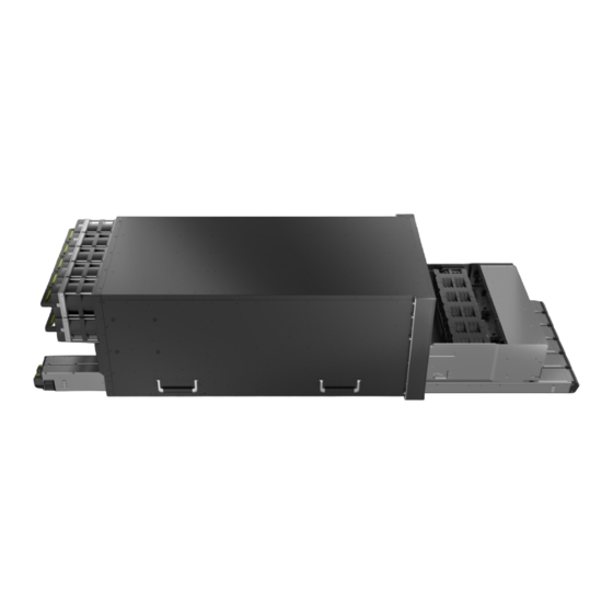
FusionServer G8600 V7 Server Technical White Paper 3 Physical Structure Physical Structure Figure 3-1 Front view GPU module enclosure System enclosure 54 V dual-input PSUs (for Chassis GPU modules) Issue 03 (2023-09-15) Copyright © xFusion Digital Technologies Co., Ltd. - Page 13 12 V PSUs (for the system Composite enclosure enclosure) I/O module 1 I/O module 2 I/O module 3 I/O module 4 Rear fan modules (used for Rear upper subrack heat dissipation of GPU modules) Chassis Issue 03 (2023-09-15) Copyright © xFusion Digital Technologies Co., Ltd.
-
Page 14: Logical Structure
FusionServer G8600 V7 Server Technical White Paper 4 Logical Structure Logical Structure Figure 4-1 Logical structure of the balanced configuration Issue 03 (2023-09-15) Copyright © xFusion Digital Technologies Co., Ltd. - Page 15 PCIe 5.0 high-speed links are modularized and cable-free. ● The Baseboard Management Controller (BMC) card integrates the BMC management chip and provides external video graphic array (VGA), management network port, and serial port. Issue 03 (2023-09-15) Copyright © xFusion Digital Technologies Co., Ltd.
-
Page 16: Hardware Description
5.2 Rear Panel 5.3 Processors 5.4 Memory 5.5 Storage 5.6 Network 5.7 I/O Expansion 5.8 PSUs 5.9 Fan Modules 5.10 Board 5.1 Front Panel 5.1.1 Appearance ● 8 x 2.5" drive configuration Issue 03 (2023-09-15) Copyright © xFusion Digital Technologies Co., Ltd. -
Page 17: Indicators And Buttons
System enclosure 54 V dual-input PSUs (for GPU modules) Slide-out label plate (with an SN label) 5.1.2 Indicators and Buttons Indicator and Button Locations ● 8 x 2.5" drive configuration Issue 03 (2023-09-15) Copyright © xFusion Digital Technologies Co., Ltd. - Page 18 ● ---: The device is operating properly. diagnosis LED ● Error code: A component is faulty. For details about the error codes, see the FusionServer G8600 V7 Server iBMC Alarm Handling. Issue 03 (2023-09-15) Copyright © xFusion Digital Technologies Co., Ltd.
- Page 19 6 seconds to forcibly power off the device. ● When the power indicator is steady yellow, you can press this button to power on the server node. Issue 03 (2023-09-15) Copyright © xFusion Digital Technologies Co., Ltd.
- Page 20 ● Blinking green at short intervals for 3 seconds and then off: The port is disabled. ● Steady green: The server configuration file is being copied from the USB device or the job is successfully completed. Issue 03 (2023-09-15) Copyright © xFusion Digital Technologies Co., Ltd.
-
Page 21: Port
– Output overcurrent or short-circuit – Output overvoltage – Short-circuit protection – Component failure (excluding failure of all components) 5.1.3 Port Port Positions ● 8 x 2.5" drive configuration Issue 03 (2023-09-15) Copyright © xFusion Digital Technologies Co., Ltd. - Page 22 VGA port Interface Description Table 5-2 Ports on the front panel Name Type Note Description Quantity VGA port DB15 Used to connect a display terminal, such as a monitor or KVM. Issue 03 (2023-09-15) Copyright © xFusion Digital Technologies Co., Ltd.
- Page 23 CD/DVD drives, an external power supply is required. Note: The number of ports varies depending on server configuration. This table lists the maximum number of ports in different configurations. Issue 03 (2023-09-15) Copyright © xFusion Digital Technologies Co., Ltd.
-
Page 24: Rear Panel
I/O module 3 12 V PSUs (for the system enclosure) BMC card FlexIO card NOTE The FlexIO card slot supports only an OCP 3.0 NIC. I/O module 1 I/O module 2 Issue 03 (2023-09-15) Copyright © xFusion Digital Technologies Co., Ltd. - Page 25 Riser module 1 in the I/O module 1 composite enclosure I/O module 2 Note: The high-performance riser module of the composite enclosure is for reference only. The actual configuration may vary. Issue 03 (2023-09-15) Copyright © xFusion Digital Technologies Co., Ltd.
-
Page 26: Indicators And Buttons
Connection status Serial port indicators indicator of the NOTE management network Reserved and unavailable port currently. UID indicator 12 V PSU indicators ● High-performance configuration Issue 03 (2023-09-15) Copyright © xFusion Digital Technologies Co., Ltd. - Page 27 Indicator State Description 54 V PSU ● Off: The corresponding front 54 V presence PSU is not detected. indicators ● Steady green: The corresponding front 54 V PSU is installed. Issue 03 (2023-09-15) Copyright © xFusion Digital Technologies Co., Ltd.
- Page 28 ● Off: The device is not being located. ● Blinking or steady blue: The device is being located. NOTE You can control the UID indicator status by pressing the UID button or using the iBMC. Issue 03 (2023-09-15) Copyright © xFusion Digital Technologies Co., Ltd.
-
Page 29: Port
V dual-input PSUs V dual-input PSUs Management network Serial port port VGA port USB 3.0 port Socket of 12 V PSU 1 Socket of 12 V PSU 2 ● High-performance configuration Issue 03 (2023-09-15) Copyright © xFusion Digital Technologies Co., Ltd. - Page 30 NOTE The management network port is a GE port that supports 100 Mbit/s and 1000 Mbit/s auto-negotiation. Issue 03 (2023-09-15) Copyright © xFusion Digital Technologies Co., Ltd.
-
Page 31: Processors
Processors used in one server must be of the same model. ● For details about the optional components, consult your local sales representative or see "OS and Parts Compatibility" in the Compatibility Checker. Issue 03 (2023-09-15) Copyright © xFusion Digital Technologies Co., Ltd. -
Page 32: Memory
Figure 5-10 Positions of the processors 5.4 Memory 5.4.1 DDR5 Memory 5.4.1.1 Memory Identifier You can determine the memory module properties based on the label attached to the memory module. Issue 03 (2023-09-15) Copyright © xFusion Digital Technologies Co., Ltd. - Page 33 ● B = 40-40-40 ● C = 42-42-42 DIMM type ● Reference design for version RDIMM D0 SPD version ● 10: SPD version ● 10: SPD versions from byte 192 to byte 447 Issue 03 (2023-09-15) Copyright © xFusion Digital Technologies Co., Ltd.
-
Page 34: Memory Subsystem Architecture
DIMM011(J) C (primary) DIMM020(C) DIMM021(K) D (primary) DIMM030(D) DIMM031(L) E (primary) DIMM040(E) DIMM041(M) F (primary) DIMM050(F) DIMM051(N) G (primary) DIMM060(G) DIMM061(O) H (primary) DIMM070(H) DIMM071(P) CPU 2 A (primary) DIMM100(A) Issue 03 (2023-09-15) Copyright © xFusion Digital Technologies Co., Ltd. -
Page 35: Memory Compatibility
● The calculation formula of total memory capacity supported is as follows: the total memory capacity equals the capacity sum of all DDR5 memory modules. Issue 03 (2023-09-15) Copyright © xFusion Digital Technologies Co., Ltd. -
Page 36: Dimm Installation Rules
● The memory modules configured must be DDR5 RDIMMs. ● The memory modules must be configured with the same number of ranks. ● Install filler memory modules in vacant slots. Issue 03 (2023-09-15) Copyright © xFusion Digital Technologies Co., Ltd. -
Page 37: Positions Of Memory Modules
A server supports up to 32 DDR5 memory modules. To maximize performance, it is advised to use balanced memory configuration. Observe the memory module installation rules when configuring memory modules. For details, see Memory Configuration Assistant. Figure 5-12 Memory installation positions Issue 03 (2023-09-15) Copyright © xFusion Digital Technologies Co., Ltd. - Page 38 FusionServer G8600 V7 Server Technical White Paper 5 Hardware Description Figure 5-13 DDR5 memory installation guidelines (2 processors) Issue 03 (2023-09-15) Copyright © xFusion Digital Technologies Co., Ltd.
-
Page 39: Memory Protection Technologies
Adaptive Data Correction - Single Region (ADC-SR) ● Adaptive Double Device Data Correction - Multiple Region (ADDDC-MR) ● Partial Cache Line Sparing (PCLS, HBM CPU only) 5.5 Storage 5.5.1 Drive Configuration and Drive Numbering Issue 03 (2023-09-15) Copyright © xFusion Digital Technologies Co., Ltd. -
Page 40: X 2.5" Drive Configuration
● I/O module 3 (2 x 2.5"): – Slots 29 to 30 support only NVMe drives ● I/O module 4 (2 x 2.5"): – Slots 31 to 32 support only NVMe drives Issue 03 (2023-09-15) Copyright © xFusion Digital Technologies Co., Ltd. - Page 41 RAID controller card. This section uses the drive numbers identified by a RAID controller card that adopts the default cabling described in "Internal Cabling" in the FusionServer G8600 V7 Server Maintenance and Service Guide. ● Drive numbering of the 8 x 2.5" drive configuration in...
- Page 42 FusionServer G8600 V7 Server Technical White Paper 5 Hardware Description Figure 5-14 Drive numbering Issue 03 (2023-09-15) Copyright © xFusion Digital Technologies Co., Ltd.
- Page 43 Drive Number Drive Number Displayed on the iBMC Identified by the RAID WebUI Controller Card ● Drive numbering of the 8 x 2.5" drive configuration in Table 5-7 (high- performance configuration) Issue 03 (2023-09-15) Copyright © xFusion Digital Technologies Co., Ltd.
- Page 44 Technical White Paper 5 Hardware Description Figure 5-15 Drive numbering Table 5-9 Drive numbering Drive No. Drive Number Drive Number Displayed on the iBMC Identified by the RAID WebUI Controller Card Issue 03 (2023-09-15) Copyright © xFusion Digital Technologies Co., Ltd.
-
Page 45: Drive Indicators
5 Hardware Description Drive No. Drive Number Drive Number Displayed on the iBMC Identified by the RAID WebUI Controller Card 5.5.2 Drive Indicators SAS/SATA Drive Indicators Figure 5-16 SAS/SATA drive indicators Issue 03 (2023-09-15) Copyright © xFusion Digital Technologies Co., Ltd. - Page 46 The NVMe drive is detected and operating properly. Blinking at 4 Hz Data is being read from or written to the NVMe drive. Steady on/blinking Blinking blue at 4 The NVMe drive is being located. Issue 03 (2023-09-15) Copyright © xFusion Digital Technologies Co., Ltd.
-
Page 47: Raid Controller Card
The high-performance configuration supports up to nine PCIe 5.0 x16 standard expansion slots. ● For details about the optional components, consult your local sales representative or see "OS and Parts Compatibility" in the Compatibility Checker. Issue 03 (2023-09-15) Copyright © xFusion Digital Technologies Co., Ltd. -
Page 48: Pcie Slots
When IB cards are used to build an IB network, ensure that the IPoIB modes of the IB cards at both ends of the network connection are the same. For details, contact technical support. 5.7.2 PCIe Slots PCIe Slots Balanced configuration Figure 5-18 PCIe slots Issue 03 (2023-09-15) Copyright © xFusion Digital Technologies Co., Ltd. - Page 49 I/O module 3 provides slots 7 to 9 and supports two 2.5" NVMe drives. ● I/O module 4 provides slots 10 to 12 and supports two 2.5" NVMe drives. ● The built-in module provides slot 21. High-performance configuration Figure 5-20 PCIe slots Issue 03 (2023-09-15) Copyright © xFusion Digital Technologies Co., Ltd.
- Page 50 Figure 5-21 PCIe riser card 1 ● PCIe riser card 2 on the built-in module Provides PCIe slot 21 when installed on the built-in module. Figure 5-22 PCIe riser card 2 Issue 03 (2023-09-15) Copyright © xFusion Digital Technologies Co., Ltd.
- Page 51 Figure 5-24 PCIe riser card 2 ● PCIe riser card 3 of the built-in module Provides PCIe slot 21 when installed on the built-in module. Figure 5-25 PCIe riser card 3 Issue 03 (2023-09-15) Copyright © xFusion Digital Technologies Co., Ltd.
-
Page 52: Pcie Slot Description
CPU 2- CPU 2- FHHL module 4 x16 (x16) Slot 11 PCIe 5.0 CPU 2- CPU 2- FHHL x16 (x16) Slot 12 PCIe 5.0 CPU 2 CPU 2- FHHL x16 (x16) Issue 03 (2023-09-15) Copyright © xFusion Digital Technologies Co., Ltd. - Page 53 The following table lists the PCIe port numbers mapped to CPUs. For details about the PCIe port number displayed on the BIOS screen, see the Server Eagle Stream Platform BIOS Parameter Reference. Issue 03 (2023-09-15) Copyright © xFusion Digital Technologies Co., Ltd.
- Page 54 CPU 1 FHHL riser card x16 (x16) pass- in the through composit enclosure Built-in Built-in Slot 21 PCIe 4.0 CPU 2 CPU 2- HHHL PCIe RAID riser card controller card Issue 03 (2023-09-15) Copyright © xFusion Digital Technologies Co., Ltd.
-
Page 55: Psus
B/D/F information of the server running the lspci command. 5.8 PSUs ● Supports hot swap. ● The PSUs are protected against short circuit. Double-pole fuse is provided for the PSUs with dual input live wires. Issue 03 (2023-09-15) Copyright © xFusion Digital Technologies Co., Ltd. - Page 56 Two power cables are required for each 54 V PSU. In single-input mode, one power cable is required for each PSU. ● For more information about the PSUs, see the FusionServer G8600 V7 Server Power Supply Technical White Paper. Issue 03 (2023-09-15)
- Page 57 The 12 V PSUs are single-input PSUs. Each PSU is configured with one power cable. ● For more information about the PSUs, see the FusionServer G8600 V7 Server Power Supply Technical White Paper. Issue 03 (2023-09-15) Copyright © xFusion Digital Technologies Co., Ltd.
- Page 58 C19 cables. It is recommended that PSU 1 be connected to the PDU of input A through a C19 cable, and PSU 2 be connected to the PDU of input B through another C19 cable. Issue 03 (2023-09-15) Copyright © xFusion Digital Technologies Co., Ltd.
- Page 59 Four 54 V 3000 W PSUs (3+1 redundancy, single-input mode) redundancy, dual-input mode) Power cables: Power cables: 2 x C13 cables + 4 x C19 cables 10 x C19 cables Issue 03 (2023-09-15) Copyright © xFusion Digital Technologies Co., Ltd.
-
Page 60: Fan Modules
CPUs, memory modules, drives, and NICs. ● Supports hot swap. ● Supports N+1 redundancy. That is, the server can work properly when a single fan fails. ● Supports intelligent fan speed adjustment. Issue 03 (2023-09-15) Copyright © xFusion Digital Technologies Co., Ltd. - Page 61 Figure 5-31 Position of the fan module on the rear panel Figure 5-32 Positions of the built-in fan modules in the system enclosure Issue 03 (2023-09-15) Copyright © xFusion Digital Technologies Co., Ltd.
-
Page 62: Board
(PORT (A-B) M. 2/J6104) Built-in USB 3.0 connector Left mounting ear (INNER USB3.0/J37) connector (L_EARBOARD/ J6080) TPM/TCM connector (TPM Front-drive backplane low- CONN/J6065) speed signal connector (FRONT HDD BP/J6082) Issue 03 (2023-09-15) Copyright © xFusion Digital Technologies Co., Ltd. -
Page 63: Drive Backplane
The reserved connector is temporarily unavailable. 5.10.2 Drive Backplane Front-Drive Backplane ● 8 x 2.5" drive pass-through backplane All drive configurations in 5.5.1.1 8 x 2.5" Drive Configuration support this backplane. Issue 03 (2023-09-15) Copyright © xFusion Digital Technologies Co., Ltd. - Page 64 Managed Drive Slot Backplane signal cable connector (HDD BP/ J12) Power connector (HDD_POWER/J14) Mini-SAS HD connector Slots 0 to 3 (PORT A/J28) Mini-SAS HD connector Slots 4 to 7 (PORT B/J1) Issue 03 (2023-09-15) Copyright © xFusion Digital Technologies Co., Ltd.
-
Page 65: Fan Boards
LEAK1/J6, LIO PRES1/J7) Fan connector (FAN5/J13, FAN4/J5, FAN3/J4, FAN2/J3, FAN1/J2) Figure 5-36 Upper 54 V fan board Fan connector (FAN1/J1, Power connector FAN2/J2, FAN3/J3, (PWR_CONN/J7) FAN4/J4, FAN5/J5) Spurious signal connector (MISC_CONN/J6) Issue 03 (2023-09-15) Copyright © xFusion Digital Technologies Co., Ltd. - Page 66 Fan board power Fan board spurious signal connector (J10) connector (J7) Guide column (J11) Fan 1 to fan 5 board power connector (PWR_CONN/J8) Fan connector (FAN10/J6, FAN9/J5, FAN8/J4, FAN7/J3, FAN6/J2) Issue 03 (2023-09-15) Copyright © xFusion Digital Technologies Co., Ltd.
-
Page 67: Ssd Adapter Board
FusionServer G8600 V7 Server Technical White Paper 5 Hardware Description 5.10.4 M.2 SSD Adapter Board Figure 5-38 M.2 SSD adapter board Signal connector (J1) High-speed connector (J2) Issue 03 (2023-09-15) Copyright © xFusion Digital Technologies Co., Ltd. -
Page 68: Nvme Adapter
FusionServer G8600 V7 Server Technical White Paper 5 Hardware Description 5.10.5 NVMe Adapter Figure 5-39 NVMe adapter Power connector (PWR- Signal connector (NVME- IN/J4) BP/J5) UBC connector (UBC1/J3) Issue 03 (2023-09-15) Copyright © xFusion Digital Technologies Co., Ltd. -
Page 69: Bmc Adapter Board (Balanced)
4C+ connector 4C+ connector (BMC_CARD/J3) (OCP1_CARD/J5) Guide pin (J11, J12) High-speed connector (J7/J8/J9/J10) Power connector (J1) LCD UART connector (UART_CONN/J6) IIC DEBUG connector (DEBUG/J14) a: The reserved connector is temporarily unavailable. Issue 03 (2023-09-15) Copyright © xFusion Digital Technologies Co., Ltd. -
Page 70: Bmc Adapter Board (High Performance)
(UBC_1A/J5) (UART/J6) UBC connector 1B NC-SI connector (UBC_1B/J4) (NCSI_CONN/J13) Riser card power Guide pins (J12/J11) connector (RISER_PWR/ J20) High-speed connectors Input power connector (J1) (J10/J9/J8/J7) a: Reserved and unavailable currently. Issue 03 (2023-09-15) Copyright © xFusion Digital Technologies Co., Ltd. -
Page 71: Product Specifications
● Min. 1.875 MB L3 cache per core ● Max. 350 W TDP NOTE The preceding information is for reference only. For details, see "OS and Parts Compatibility" in the Compatibility Checker. Issue 03 (2023-09-15) Copyright © xFusion Digital Technologies Co., Ltd. - Page 72 – A server must use DDR5 DIMMs of the same P/N code. NOTE The preceding information is for reference only. For details, see "OS and Parts Compatibility" in the Compatibility Checker. Issue 03 (2023-09-15) Copyright © xFusion Digital Technologies Co., Ltd.
- Page 73 For details about the RAID controller card, see the V7 Server RAID Controller Card User Guide. NOTE If the BIOS is in legacy mode, the 4K drive cannot be used as the boot drive. Issue 03 (2023-09-15) Copyright © xFusion Digital Technologies Co., Ltd.
- Page 74 OS is provided. ● If both the front and rear VGA ports are connected to monitors, only the monitor connected to the front VGA port displays information. Issue 03 (2023-09-15) Copyright © xFusion Digital Technologies Co., Ltd.
-
Page 75: Environmental Specifications
● Storage humidity (within six months): 8% to 80% ● Storage humidity (within one year): 20% to 75% ● Maximum rate of humidity change: 20% per hour Air volume 280CFM~1600CFM Issue 03 (2023-09-15) Copyright © xFusion Digital Technologies Co., Ltd. - Page 76 – LpAm: 55.2 dBA ● Operating: – LWAd: 7.18 Bels – LpAm: 55.5 dBA NOTE Actual sound levels generated during operation vary depending on the configuration, load, and ambient temperature. Issue 03 (2023-09-15) Copyright © xFusion Digital Technologies Co., Ltd.
- Page 77 6 months in unpacked/packed and powered-off state ● The maximum preservation duration is determined according to the preservation specifications provided by drive vendors. For details, see the manuals provided by drive vendors. Issue 03 (2023-09-15) Copyright © xFusion Digital Technologies Co., Ltd.
-
Page 78: Physical Specifications
55 mm (2.17 in.) Zd (thickness of the silkscreen): 15 mm (0.59 in.) Xa (maximum width of the cabinet): 482.6 mm (19.00 in.) Xb (width of the chassis): 447 mm (17.60 in.) Issue 03 (2023-09-15) Copyright © xFusion Digital Technologies Co., Ltd. - Page 79 ● Packaging materials: 30.1 kg (66.36 lb) Power consumption The power consumption parameters vary with server configurations, including the configurations complying with EU energy-related products (ErP) requirements. Use Power Calculator to obtain specific information. Issue 03 (2023-09-15) Copyright © xFusion Digital Technologies Co., Ltd.
-
Page 80: Software And Hardware Compatibility
● If the customer has requirements on hardware performance consistency, specify the specific configuration requirements (for example, specific drive models, RAID controller cards, or firmware versions) in the presales phase. Issue 03 (2023-09-15) Copyright © xFusion Digital Technologies Co., Ltd. -
Page 81: Safety Instructions
Discontinue any dangerous operations and take protective measures. Report anything that could cause personal injury or device damage to a project supervisor. ● Do not move devices or install cabinets and power cables in hazardous weather conditions. Issue 03 (2023-09-15) Copyright © xFusion Digital Technologies Co., Ltd. - Page 82 Fasten the strap buckle and ensure that the ESD wrist strap is in contact with your skin. Insert the ground terminal attached to the ESD wrist strap into the jack on the grounded cabinet or chassis. Issue 03 (2023-09-15) Copyright © xFusion Digital Technologies Co., Ltd.
- Page 83 Transportation precautions include but are not limited to: ● The logistics company engaged to transport the device must be reliable and comply with international standards for transporting electronics. Ensure that the Issue 03 (2023-09-15) Copyright © xFusion Digital Technologies Co., Ltd.
-
Page 84: Maintenance And Warranty
People's Republic of China (AQSIQ) For more information about safety instructions, see Server Safety Information. 8.2 Maintenance and Warranty For details about the maintenance policy, visit Customer Support Service. Issue 03 (2023-09-15) Copyright © xFusion Digital Technologies Co., Ltd. - Page 85 FusionServer G8600 V7 Server Technical White Paper 8 Safety Instructions For details about the warranty policy, visit Warranty. Issue 03 (2023-09-15) Copyright © xFusion Digital Technologies Co., Ltd.
-
Page 86: System Management
If the server is configured with the LCD module, the LCD can directly obtain device information from the iBMC. ● System maintenance interface – The virtual KVM and virtual media functions facilitate remote maintenance. Issue 03 (2023-09-15) Copyright © xFusion Digital Technologies Co., Ltd. - Page 87 Compared with the standard edition, the iBMC advanced edition provides more advanced features, such as: – Implements the OS deployment using Redfish. – Collect the original data of intelligent diagnosis using Redfish. Issue 03 (2023-09-15) Copyright © xFusion Digital Technologies Co., Ltd.
-
Page 88: Certification
EN 55032:2015+A11:2020 CISPR 32:2015+A1:2019 EN IEC 61000-3-12:2011 EN 61000-3-11:2017 EN 55035:2017+A11:2020 CISPR 35:2016 EN 55024:2010+A1:2015 CISPR 24:2010+A1:2015 ETSI EN 300 386 V2.1.1:2016 RoHS: EN IEC 63000:2018 ErP: Commission Regulation(EU) 424/2019 Issue 03 (2023-09-15) Copyright © xFusion Digital Technologies Co., Ltd. - Page 89 ETSI EN 300 386 V2.1.1:2016 RoHS: EN IEC 63000:2018 ErP: Commission Regulation(EU) 424/2019 China RoHS SJ/T-11364 GB/T 26572 FCC PART 15 Canada ICES-003 Japan VCCI VCCI 32-1 Global IEC 62368-1:2014 Issue 03 (2023-09-15) Copyright © xFusion Digital Technologies Co., Ltd.
-
Page 90: A Appendix
Product SN NOTE For details, see A.2 Product Reserved space for customized Pressure-proof label label NOTE This label warns users not place any objects on top of a rack- mounted device. Issue 03 (2023-09-15) Copyright © xFusion Digital Technologies Co., Ltd. -
Page 91: Nameplate
Table A-1 Nameplate description Description Server model NOTE For details, see Nameplate. Device name Power supply requirements Vendor information Certification marks A.1.1.2 Certificate Figure A-3 Certificate example Table A-2 Certificate description Description Order Issue 03 (2023-09-15) Copyright © xFusion Digital Technologies Co., Ltd. - Page 92 ● Digits 0 to 9 indicate 0:00 to 9:00. ● Letters A to H indicate 10:00 to 17:00. ● Letters J to N indicate 18:00 to 22:00. ● Letters P to Q indicate 23:00 to 24:00. Issue 03 (2023-09-15) Copyright © xFusion Digital Technologies Co., Ltd.
-
Page 93: Quick Access Label
Subnet mask of the default iBMC management network port Default iBMC username Default iBMC password Default BIOS password Technical support website P/N code QR code NOTE Scan the QR code to obtain technical support resources. Issue 03 (2023-09-15) Copyright © xFusion Digital Technologies Co., Ltd. -
Page 94: Chassis Internal Label
● The quick start guide is optional. For details, see the actual product. A.1.3 Chassis Tail Label Figure A-7 Chassis tail label NO TE For details about the warning labels, see the Server Security Information. Issue 03 (2023-09-15) Copyright © xFusion Digital Technologies Co., Ltd. -
Page 95: Product Sn
Description SN ID (two characters), which is 21. Material identification code (eight characters), that is, the processing code. Vendor code (two characters), that is, the code of the processing place. Issue 03 (2023-09-15) Copyright © xFusion Digital Technologies Co., Ltd. -
Page 96: Operating Temperature Limitations
100GE ports or ports of higher rate are not supported. ● OCP 3.0 NICs with 100GE ports or ports of higher rate are not supported. ● H800 GPU modules are not supported. Issue 03 (2023-09-15) Copyright © xFusion Digital Technologies Co., Ltd. -
Page 97: Nameplate
Core temperature of the BMC card 1711 chip SSD Max Temp Maximum SSD temperature (reported by BMA) SSD Disk$ Temp SSD temperature HDD Max Temp Maximum HDD temperature (reported by BMA) Issue 03 (2023-09-15) Copyright © xFusion Digital Technologies Co., Ltd. - Page 98 Mainboard or CPU N diagnosis health status N indicates the CPU number. The value is 1 or CPUN Prochot CPU Prochot CPUN N indicates the CPU number. The value is 1 or Issue 03 (2023-09-15) Copyright © xFusion Digital Technologies Co., Ltd.
- Page 99 Maximum internal temperature of the PSU PS$ Inlet Temp PSU air inlet temperature PS$ Status PSU fault status PS Redundancy Redundancy failure due to PSU removal Power Server input power Issue 03 (2023-09-15) Copyright © xFusion Digital Technologies Co., Ltd.
- Page 100 N indicates the fan number. The value ranges from 1 to 8. DIMMN DIMM status DIMM N N indicates the DIMM slot number MEM Power Memory power Memory Issue 03 (2023-09-15) Copyright © xFusion Digital Technologies Co., Ltd.
- Page 101 PCIe RAID$ Temp PCIe RAID controller card PCIe RAID controller card temperature PCIE Status PCIe status error PCIe card PCIe$ OP Temp PCIe card optical module PCIe card temperature sensor Issue 03 (2023-09-15) Copyright © xFusion Digital Technologies Co., Ltd.
- Page 102 Op. Log Full Operation log full or events being cleared Sec. Log Full Security log full or events being cleared Host Loss System monitoring software (BMA) link loss detection Issue 03 (2023-09-15) Copyright © xFusion Digital Technologies Co., Ltd.
-
Page 103: B Glossary
DEC. Ethernet uses the Carrier Sense Multiple Access/Collision Detection (CSMA/CD) access method and allows data transfer over various cables at 10 Mbit/s. The Ethernet specification is the basis for the IEEE 802.3 standard. Issue 03 (2023-09-15) Copyright © xFusion Digital Technologies Co., Ltd. -
Page 104: F-J
A PCI system can be transformed to a PCIe system by modifying the physical layer instead of software. PCIe delivers a faster speed and can replace almost all AGP and PCI buses. Issue 03 (2023-09-15) Copyright © xFusion Digital Technologies Co., Ltd. -
Page 105: U-Z
A unit defined in International Electrotechnical Commission (IEC) 60297-1 to measure the height of a cabinet, chassis, or subrack. 1U = 44.45 mm. UltraPath A point-to-point processor interconnect developed by Interconnect (UPI) Intel. Issue 03 (2023-09-15) Copyright © xFusion Digital Technologies Co., Ltd. -
Page 106: C Acronyms And Abbreviations
Advanced Encryption Standard New Instruction Set Address Resolution Protocol Advanced Vector Extensions Backup Battery Unit BIOS Basic Input Output System Baseboard Management Controller China Compulsory Certification Calendar Day Conformite Europeenne Common Information Model Command-line Interface Issue 03 (2023-09-15) Copyright © xFusion Digital Technologies Co., Ltd. -
Page 107: F-J
Enterprise Resource Planning European Telecommunication Standards C.2 F-J FB-DIMM Fully Buffered DIMM Fiber Channel Federal Communications Commission FCoE Fibre Channel Over Ethernet File Transfer Protocol Gigabit Ethernet GPIO General Purpose Input/Output Issue 03 (2023-09-15) Copyright © xFusion Digital Technologies Co., Ltd. -
Page 108: K-O
Internet Group Message Protocol IOPS Input/Output Operations per Second Internet Protocol Intelligent Power Capability IPMB Intelligent Platform Management Bus IPMI Intelligent Platform Management Interface C.3 K-O Keyboard, Video, and Mouse Issue 03 (2023-09-15) Copyright © xFusion Digital Technologies Co., Ltd. -
Page 109: P-T
Network Controller Sideband Interface Open Compute Project C.4 P-T PCIe Peripheral Component Interconnect Express Power Distribution Unit Physical Layer PMBUS Power Management Bus PMem Persistent Memory Power OK Pulse-width Modulation Preboot Execution Environment Issue 03 (2023-09-15) Copyright © xFusion Digital Technologies Co., Ltd. - Page 110 Serial Over LAN SONCAP Standards Organization of Nigeria-Conformity Assessment Program Solid-State Drive Streaming SIMD Extension TACH Tachometer Signal Turbo Boost Technology Trusted Computing Group Trusted Cryptography Module Total Cost of Ownership Issue 03 (2023-09-15) Copyright © xFusion Digital Technologies Co., Ltd.
-
Page 111: U-Z
Voluntary Control Council for Interference by Information Technology Equipment Video Graphics Array VLAN Virtual Local Area Network Voltage Regulator-Down VROC Virtual RAID on CPU WEEE Waste Electrical and Electronic Equipment Issue 03 (2023-09-15) Copyright © xFusion Digital Technologies Co., Ltd. - Page 112 FusionServer G8600 V7 Server Technical White Paper C Acronyms and Abbreviations WSMAN Web Service Management Issue 03 (2023-09-15) Copyright © xFusion Digital Technologies Co., Ltd.
Need help?
Do you have a question about the FusionServer G8600 V7 and is the answer not in the manual?
Questions and answers