Table of Contents
Advertisement
Quick Links
Advertisement
Table of Contents

Related Manuals for Kanomax 3444


Summary of Contents for Kanomax 3444
- Page 1 Digital Dust Monitor Model 3444 User’s Manual...
- Page 2 List of Components ■Standard Items Model Quantity Main Body 3444-00 Built-in:1 Pump Filter 3444-60 Spare:1 Built-in:1 Purge Filter 3442-03 Spare:1 Shoulder belt AA Battery LCD protection sheet 3444-61 USB cable 3444-20 Measurement Software 3444-40 User’s Manual ■Available Accessories Items Model...
- Page 3 Important Safety Information The symbols for the warnings used in this manual are defined below: Classifications Danger Warnings in this classification indicate a danger that may result in serious injury or death if not observed. Caution Warnings in this classification indicate a risk of damage to the product that may void the product warranty if not observed.
- Page 4 Danger (Disassembly prohibited) Never disassemble, modify, or repair the product. Short circuits and adjustment malfunctions may cause performance to be unmaintained. (Prohibition of use) When using AC power, use the optional dedicated AC adapter. Failure to do so may cause malfunction. There is a risk of overheating and ignition, which may lead to fire or accident.
- Page 5 Important (Prohibition) Do not measure this unit in a place with high temperature, low temperature, or high humidity. Also, do not leave the unit in direct sunlight for long periods of time. The product may not operate properly outside the operating temperature range. Use within the operating range.
- Page 6 Laser class This device is a Class 1 laser product based on the following standards. ● EN60825-1: 2014 CLASS 1 LASER PRODUCT EN60825-1: 2014 Handling of Laser Light DANGER-This device uses a Class 3B laser diode as the sensor light source inside the main case.
-
Page 7: Table Of Contents
Table of Contents Part Names and Functions ................... 8 Overview............................8 Principle of Measurement ......................8 Part Names and Functions ......................9 How to attach the shoulder strap ....................12 Getting Started ......................13 Power supply ..........................13 2.1.1 Installing Batteries ......................13 2.1.2 Connecting the AC adapte ..................... - Page 8 I/O cable (Communication) ......................61 Specifications ......................62 Trouble Shooting ....................... 64 Check power ..........................64 Checking during measurement ....................64 Background check ......................... 65 Sensitivity check ..........................66 Calibration check ........................... 67 Analog output ..........................67 Pulse output ........................... 68 Alarm output ..........................
-
Page 9: Part Names And Functions
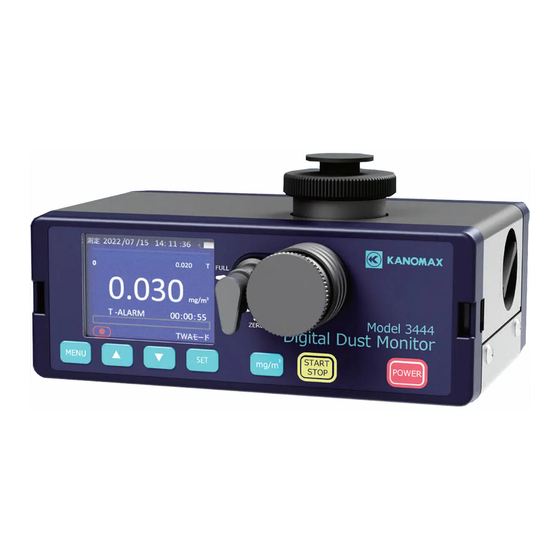
Part Names and Functions 1.1 Overview This product (Model 3444) is a light scattering portable dust monitor using a semiconductor laser light source. Measurement data can be displayed on the LCD screen and stored in the internal memory. Stored data can be read out with the included software. -
Page 10: Part Names And Functions
1.3 Part Names and Functions ⑫Filter open/close knob ⑧Sensitivity control knob ⑪Filter holder ⑨Inlet ⑦Display ⑬belt clasp ⑥MEMU ⑤△▽key ④SET key ②START/STOP ①POWER key ③mg/m ⑩Inlet cover ⑭Exhaust port ⑲Screw hole for tripod fixing ⑯AC adapter jack ⑮Pump Filter Cap ⑰I/O Connector ⑱USB Type-C Connector... - Page 11 Do not block the air exhaust port when device is in operation. ⑮ Pump Filter Cap A built-in filter inside for pump protection. (See “4.1.2 Replacing the pump filter” for replacement instructions.) ⑯ AC adapter jack Connect the optional AC adapter (3444-10).
- Page 12 ⑰ I/O Connector Connect the optional output cable (analog) (3444-30). Analog output: Outputs a voltage equivalent to 0 to 1 V for 0 to 1,000 CPM or 0 to 10,000 CPM. Analog output: A voltage equivalent to 0 to 1 V is output for 0 to 1,000 CPM or 0 to 10,000 CPM.
-
Page 13: How To Attach The Shoulder Strap
1.4 How to attach the shoulder strap Pass the end of the shoulder belt through the hole in the belt clasp of the dust monitor, fold it back and secure it through the shoulder belt attachment. Adjust the length of the shoulder strap by the length of the belt that goes through the attachment. -
Page 14: Getting Started
Getting Started 2.1 Power supply The instrument can be powered by batteries or an optional dedicated AC adapter (3444-10). Please set the battery or optional AC adapter. 2.1.1 Installing Batteries ② ① Press the battery box lid claw in the ②... - Page 15 The remaining battery charge is displayed in 10 levels. When the remaining battery charge is low, the battery display would turn out to red. Please connect the optional AC adapter (3444-10) instead or stop the measurement and replace the batteries with new ones.
-
Page 16: Precautions During Storage And Transportation Of The Unit
2.2 Precautions during storage and transportation of the unit ◆ Precautions for storing the main unit CAUTION: When not in use for an extended period of time, remove the battery in use from the battery compartment. Corrosion of the batteries may cause contact failure. -
Page 17: Cleaning
2.3 Cleaning To maintain the accuracy of instrument, the instrument must be cleaned before use. (In the case of a one-day use, please clean before and after the first and last measurement.) Filter open/close knob Filter open/close knob Inlet cover Sensitivity control knob ②... -
Page 18: User Calibration
2.4 User calibration To maintain the accuracy of instrument, please perform user calibration before use. (In the case of a one-day use, please do the user calibration before the first measurement.) User calibration includes background adjustment and sensitivity adjustment (SPAN). Please run background adjustment and sensitivity adjustment in the order. -
Page 19: Screen Descriptions And Operating Procedures
Screen Descriptions and Operating Procedures 3.1 Startup screen Press the [POWER] button to turn on the power, which will display the startup screen and warm up the unit for 10 seconds. Screen will display the model’s name, version, serial number and remaining warm-up time. -
Page 20: Initial Screen
3.2 Initial Screen After the warm-up is completed, ② ① the screen shown below will be displayed. <Explanation of each part> ① Date, time ③ ② Battery level ④ ⑤ (See “2.1 Power supply”) ⑦ ③ Relative concentration bar ④ Measure value ⑧... - Page 21 <Key Instruction> Operation [START/STOP] Starts and stops the measurement. Press after the measurement finished to display the mass [mg/m concentration. [MENU] Open menu. (See “3.4 Menu”) <Measurement Mode> There are five measurement modes, all the modes could be set on the menu screen. (See “3.4.1 Measurement Mode”) 1.
-
Page 22: Screen During Measurement
3.3 Screen during measurement During measurement, the total number of particles counted and the instantaneous value corresponding to the relative concentration per minute (CPM: Count Per Minute) are displayed in the indicated value position and concentration bar graph, respectively. The remaining time of measurement is displayed on the time bar graph and the remaining time display. -
Page 23: Menu
3.4 Menu Press the [MENU] key on the initial screen displays the menu screen. On the menu screen, the following items can be selected. Item Description MEASURE MODE Sets the measurement mode. (See “3.4.1 Measurement Mode”) CALIBRATION User background adjustment and sensitivity adjustment (SPAN). -
Page 24: Measure Mode
3.4.1 MEASURE MODE When enter the “MEASURE MODE” screen, the screen shown on the left will be displayed. On this screen, you can select a measurement mode from the following five modes. ・ STANDARD MODE ・ FREE MODE ・ MANUAL MODE ・... - Page 25 A)STANDARD MODE In “STANDARD MODE”, the required measurement time must be set in advance. The selectable measurement times are 6, 10, 30 seconds or 1, 2, 3, 5, 10 minutes. When pressing the [SET] key on the “STANDARD MODE” , the background color of the time setting field will be highlighted, then it is capable to use [△][▽] keys to change the time setting.
- Page 26 B)FREE MODE In “FREE MODE” , the measurement time can be set in 1-second increments for the range of 1~59 seconds and in 1-minute increments for the range of 1~99 minutes. While the time setting is highlighted, use the [△][▽] keys to change the measurement time.
- Page 27 D)TWA MODE In TWA (Time Weighted Average) MODE, this function measures the time-weighted average concentration and notifies the user with an alarm when it exceeds a set threshold value. There are three types of threshold values can be set as following. TLV-C value, which is the concentration that must not be exceeded even momentarily.
- Page 28 1) TWA TIME Set the value in the order of hours → minutes. Use the [△][▽] keys to move cursor/change value. Use [SET] key to select/set next value/apply the change. [MENU] key to cancel/return. The input range of the measurement time is from 1 minute to 48 hours, and the setting is made in units of 1 minute.
- Page 29 3) STEL VALUE(Threshold Limit Value - Short Term Exposure Limit : Short-Time Exposure Limits) The TLV-STEL alarm will sound when the latest 15-minute moving average concentration (mg/m3) exceeds this set value. And a message “S-ALARM” will be displayed on the screen. Also, the alarm will go off if the concentration exceeds the TLV-TWA set value over 5 times within 8 hours, or the concentration exceeds the TLV-TWA set value at the last 60 minutes of the measurement.
- Page 30 4) TWA VALUE (Threshold Limit Value - Time Weighted Average: Time weighted average) The TLV-TWA alarm will sound when the average concentration (mg/m3) from the start to the end of measurement in TWA mode exceeds the set value. And a message “T-ALARM” will be displayed on the screen. If the set measurement time is less than 8 hours, the set time will be applied as is.
- Page 31 <Alarm Condition> <TLV-TWA Alarm> TLV-TWA Alarm (When the 8hours time weighted average exceeds the TWA) mg/m *The same applies at the end of the TLV-C measurement. TLV-STEL TLV-TWA 濃 度 Time t Average concentration value <TLV-C Alarm> TLV-C alarm (When instantaneous concentration exceeds C) mg/m TLV-C TLV-STEL...
- Page 32 <TLV-STEL Alarm> TLV-STEL alarm (When the short-time exposure limit value STEL mg/m is exceeded) TLV-C TLV-STEL TLV-TWA 濃 度 Time t 15-minute moving average TLV-STEL alarm TLV-STEL alarm (Occurs when the short-term exposure (Occurs when short-time limit exceeds the TWA twice in 60 exposure limit exceeds the TWA minutes) more than 5 times within 8hours)
- Page 33 <Alarm classification> The alarm output sound varies depending on the content of the detected alarm. Alarms in TWA mode are displayed on the measurement screen and outputting a respective sound as shown below. Note that the alarm cannot be output to the external terminal. Alarm Sound TLV-C(C-ALARM)...
- Page 34 E)CALCULATION MODE In “CALCULATION MODE”, measurement time and settings can be set and scheduled. Use the [△][▽] keys to move cursor/change value. Use [SET] key to select/set next value/apply the change. [MENU] key to cancel/return. Item Description START DATE / Date and time to start measurement TIME SAMPLING...
- Page 35 1)START DATE / TIME Set START DATE/ TIME values in the order of year → month → day → hour → minute → second. 2)SAMPLING TIME Set SAMPLING TIME value in the order of hour → minute. The input range of the sampling time can be set from 1 second to 99 minutes and 59 seconds.
- Page 36 <Screen while waiting for measurement> Wait until the set time or press the [START/STOP] key to start the measurement earlier. <Screen during measurement> During measurement, press the [START/STOP] key to suspend/restart the measurement; press [△][▽] keys to switch to the graph screen. <Graph>...
-
Page 37: Calibration
3.4.2 CALIBRATION For a proper user calibration, please perform cleaning process before starting user calibration and warm up the instrument over 20 minutes. For user calibration, please refer to “2.4 User Calibration” Select “User Calibration” on the menu screen to start user calibration. - Page 38 <SPAN> Next do the sensitivity adjustment, move the cursor to “SPAN” in the calibration menu, press [SET] key entering the sensitivity adjustment screen and make sure the background adjustment is finished before starting sensitivity adjustment. Follow the instructions shown on the screen, 1.
-
Page 39: File
3.4.3 FILE Selecting “FILE” on the menu screen. Saved measurement data can be managed here. You can view or delete data, turn ON/OFF the data saving function, and check the remaining memory. “ A)DATA LIST Move the cursor to “DATA LIST” and press the [SET] key. Data from “STANDARD MODE”... - Page 40 The time series graph of the measured data can display up to 60 data on one screen. The horizontal axis of the graph is time, and the vertical axis is relative concentration. The scale of the vertical axis will be set automatically. Press the [mg/m³] key to switch the units between CPM &...
- Page 41 (2) Delete the data before measurement to free up memory. (3) Install the included measurement software and start measuring with a PC. (For details on the installation and measurement, refer to the “Digital Dust Monitor Application Manual” included in the measurement software (3444-40).)
-
Page 42: Utility
3.4.4 UTILITY Select “UTILITY” on the menu screen. The functions are shown in the table below. Use the [△][▽] keys to move the cursor. Press the [SET] key to select and set each item. Press the [MENU] key to cancel and return. Item Contents CLEANING... - Page 43 B)DATE&TIME This function is for date and time settings. Use [△][▽] keys to move cursor and change value. Use [SET] key to select and set. Press the [MENU] key to return to the menu screen. Item Contents Style Set the date display format. Date Set the date.
- Page 44 C)K FACTER Set the K value (mass concentration conversion factor). Use [△][▽] keys to change value. *The setting range is from0.1 to 9.9. Press the [SET] key to apply the change. Press the [MENU] key to cancel and return. In order to convert from the measured value (CPM) of this instrument to mass concentration (mg/m ), it is necessary to determine the mass concentration conversion factor.
- Page 45 D)LCD / BEEP Screen settings and beep sound ON/OFF. Use [△][▽] keys to move the cursor. Use [SET] key to select and apply changes. Press the [MENU] key to return. Item Contents CONTRAST Set the contrast setting for the screen. BACKLIGHT OFF Set the backlight off time setting.
- Page 46 (1) Data update interval ..Output data is always updated at 1 second intervals. (2) Load impedance .... 1kΩ or more (3) Output cable ....Please purchase the optional output cable (3444-30). Refer to “5.6 Output Cable (Analog)” for output cable connection.
- Page 47 (3) Output form and specification ..Photo-coupler output (No-voltage contact output: collector-emitter) Model: TLP187 Maximum applied voltage: 300V DC Maximum current: 150mA (4) Output cable ......Please purchase the optional output cable (3444-30) Refer to “5.6 Output Cable (Analog)” for output cable connection.
- Page 48 CPM value (Instantaneous value) every second. (Output terminal circuit) + - *The CPM value (Instantaneous value) for the alarm judgment is different from the count value on the display screen. *Please prepare the optional output cable (3444-30).
- Page 49 (3) Output form & specification ... Photo-coupler output (No-voltage contact output: collector-emitter) Model: TLP187 Maximum applied voltage: DC300V Maximum current: 150mA (4) Output cable .........Please purchase the optional output cable (3444-30) Refer to “5.6 Output Cable (Analog)” for output cable connection. Pulse output Description Outputs pulses...
- Page 50 F)LANGUAGE Language setting screen. Use the [△][▽] keys to switch alternately between Japanese and English. Press the [SET] key to save the change, the device will reboot automatically. Press the [MENU] key to cancel and return.
-
Page 51: Serial Communication
① Use the included USB communication cable to connect with PC. ② Install the attached measurement software on the host computer. (For details on software installation, refer to the “Measurement Software Instruction Manual for Light Scattering Digital Dust monitor” included in the measurement software (3444-40). USB cable for communication... -
Page 52: Measurement Procedure
3.6 Measurement Procedure To ensure accurate measurements, let the product to fully adapt to the ambient temperature where it will be used (more than 20 minutes). Filter open/close knob Filter open/close knob Inlet cover Sensitivity control knob ④ ④ ④ ⑤... -
Page 53: Replacement Of Consumables
Replacement of Consumables 4.1 Replacing the filter If errors keeps occurring when doing calibration, or if the purge filter is obviously damaged or extremely dirty, please replace the purge filter. The time to replace the pump filter depends on the measured concentration and the time of use. If the flow rate decreases, replace the pump filter. -
Page 54: Pump Filter Replacement
4.1.2 Pump filter replacement <Preparation of replacement parts> Use the replacement pump filter included with the product or purchase the optional pump filter (3444-60). <Filter Replacement> ① Turn the pump filter cap counterclockwise in the direction shown in figure and pull it out. -
Page 55: Replacing The Lcd Protective Sheet
Attach the LCD protective sheet if necessary. <Preparation of replacement parts> Please use the LCD protective sheet included with the product or purchase the optional LCD protective sheet (3444-61). <LCD protective sheet replacement> ① Remove the LCD protective sheet to be replaced. -
Page 56: Optional Products
Tube can be attached to the inlet of the dust monitor by installing the Tubing Connection Inlet Adapter (3444-73). Please use flexible tube with an inner diameter of 6 to 7 mm. * This product does not include the tube. -
Page 57: Cyclone Connection Adapter
5.2 Cyclone connection adapter The Cyclone Connection Adapter (3444-74) is a dedicated connection adapter for Traditional 10 mm Nylon Cyclone (made by SENSIDYNE). By installing a cyclone connection adapter and connecting a cyclone, particles with a diameter of 4 μm or less can be classified and measured. For more information about the cyclone, please contact our customer support or distributor. -
Page 58: Tripod Fixing L Angle
5.3 Tripod Fixing L Angle The tripod-fixing L-angle (3444-72) can be used to mount the dust monitor on a tripod with the inlet of the dust monitor facing up. * Please prepare a tripod (able to withstand load of 3 kg or more). -
Page 59: Protector
5.4 Protector When the dust monitor is mounted on a tripod, a protector (3444-70) can be installed to cushion the impact on the dust monitor body when overturned. <Mounting Instructions> Align the tripod fixing screw hole on the side of the dust monitor with the hole on the protector, place the protector between the dust monitor and the L-shaped tripod fixing angle, and tighten the screw on the L-shaped tripod fixing angle. -
Page 60: Dust Monitor Cover
5.5 Dust monitor Cover A dust monitor cover (3444-71) can protect the main unit from dust and dirt. The dust monitor can be operated while it is put in the dust monitor cover and can be used with the AC adapter, USB cable for communication, etc. -
Page 61: Output Cable (Analog)
5.6 Output cable (Analog) The output cable (analog) (3444-30) is used for analog output, pulse output, and alarm output. Insert the plug of the output cable (analog) into the input/output connector on the side of the main unit. I/O connector... -
Page 62: I/O Cable (Communication)
5.7 I/O cable (Communication) The I/O cable (communication) (3444-21) is used for RS-232C communication and external power supply. Insert the plug of the I/O cable (communication) into the I/O connector on the side of the main unit. Plug Signal table PC D-Sub9pin... -
Page 63: Specifications
Specifications Name Light scattering digital dust monitor Model Model 3444 0.001~10.000 mg/m Range (1CPM=0.001 mg/m at standard particles) Accuracy ±(10% of indicated value+1)count Linearity ±5% of indicated value ① Standard mode (6,10,30 seconds, 1,2,3,5,10 minutes) ② Free mode (set from 1 to 59 seconds or from 1 to 99 minutes) ③... - Page 64 Shoulder strap, 6 AA size dry cell batteries (for testing), LCD Accessory protection sheet, USB cable for communication, measurement software, instruction manual. Output cable (analog), I/O cable (communication), USB cable for communication, tube connection inlet adapter, cyclone connection Optional items adapter, tripod fixing L angle, dust monitor cover, protector, pump filter, purge filter, AC adapter...
-
Page 65: Trouble Shooting
Trouble Shooting 7.1 Check power Problem Possible cause(s) / Solution(s) Reference The screen display does not ・In case of batteries: Batteries are depleted. appear or turns off Turn off the power and replace the batteries. immediately after turning on ・For AC adapter: Make sure using a dedicated AC the power switch. -
Page 66: Background Check
7.3 Background check Problem Possible cause(s) / Solution(s) Reference Inlet cover is not raised up or not fully raised. 9、36 Raise up (close) inlet cover correctly. The purge filter is clogged. Please replace with a new purge filter. The inside of the optical system is contaminated. Be aware that relatively light particles such as carbon and resin can enter the optics and cause elevated background readings. -
Page 67: Sensitivity Check
7.4 Sensitivity check Problem Possible cause(s) / Solution(s) Reference The sensitivity control knob is not set to the “FULL” side. 9、36 Turn it fully to the “FULL” side. Value is lower than the The product is used outside the operating ambient reference CPM value. -
Page 68: Calibration Check
7.5 Calibration check Problem Possible cause(s) / Solution(s) Reference The specified background adjustment range is exceeded. Unable to complete If the background adjustment range exceeds ±20 counts background adjustment. from the manufacturer's shipment, a calibration error has 17、36 (BACKGROUND) occurred. Please contact our service center or distributor for repair. -
Page 69: Pulse Output
7.7 Pulse output Problem Possible cause(s) / Solution(s) Reference The plug is not properly inserted to the output terminal. No output. Make sure using a dedicated output cable. Make sure to use the voltage and current within the rated Output signal levels are range. -
Page 70: Warranty And After-Sales Service
Warranty and After-Sales Service The limited warranty set below is given by KANOMAX JAPAN, Inc. (hereafter referred to as “KJI”) with respect to this instrument, its attachment parts including standard accessories (hereafter referred to as “PRODUCT”) that you have purchased. PRODUCT you have purchased shall be the only one that the limited warranty stated herein applies to. -
Page 71: Contact Information
2-1 Shimizu, Suita City, Osaka 565-0805, Japan TEL: 81-6-6877-0183 FAX: 81-6-6879-5570 URL: http://www.kanomax.co.jp E-Mail: sales@kanomax.co.jp KANOMAX JAPAN INC. ©2023 Reprinting of part or the whole of the contents of this manual is strictly forbidden. The contents of this manual are subject to change without notice.
Need help?
Do you have a question about the 3444 and is the answer not in the manual?
Questions and answers