Table of Contents
Advertisement
Quick Links
Advertisement
Table of Contents

Subscribe to Our Youtube Channel
Related Manuals for Kanomax 3950


Summary of Contents for Kanomax 3950
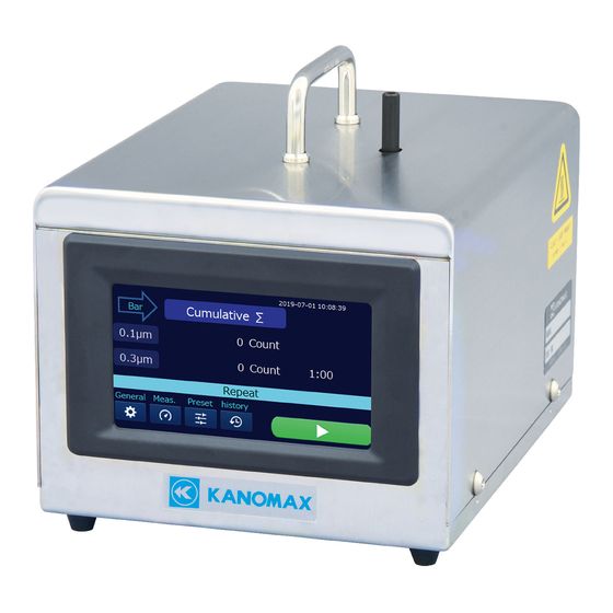
- Page 1 0.1μm Particle Counter MODEL 3950 User Manual...
- Page 3 List of Components ■ Standard Item Model Functions Main Unit Main unit 3950 AC Adapter Exclusive adapter 3910-08 USB Cable Communicates with the PC. Zero Filter Cleans the air flow path inside the device with 3950-60 clean air. Tygon Tube (1 m) Connects to the inlet to perform a measurement.
- Page 4 Important Safety Information The symbols for the warnings used in this manual are defined below: Classifications Warning Warnings in this classification indicate risks that may result in serious injury or death if not observed. Caution Warnings in this classification indicate risks that may result in injury or damage to the surrounding objects if not observed.
- Page 5 Failure to observe the above may cause electric shock, fire hazard, or damage. Please contact your local distributor or Kanomax service center for repair. Caution (Handle properly)Pull out the plug when the instrument is not in use.
-
Page 6: Table Of Contents
Table of Contents Part Names and Functions ....................5 Preparation Before Measurement ..................6 AC adapter ......................6 Warm-up ....................... 6 Measurement Procedures ....................6 Internal Cleaning ....................6 Measurement ......................6 Errors ........................7 User Interface ........................7 Title Screen ......................7 Main Screen ...................... -
Page 7: Part Names And Functions
Part Names and Functions ① ③ ⓸ ⓺ ② ⓻ ⓹ Name Functions ① Inlet Suction volume : 2.83 L/min. Outer diameter : 6.4 mm ② DC Power Terminal Connects to the main unit with the AC Adapter. ③ Communication Terminal Communicates in the RS-485 method. -
Page 8: Preparation Before Measurement
Preparation Before Measurement AC adapter Be sure to use the provided AC adapter when using the Main unit. Warm-up If the device is brought in from a different temperature place, prior to a measurement, let the device allow adapt the current temperature environment. Be sure to warm up the device at least for 10 minutes before starting a measuring. -
Page 9: Errors
Errors The following errors can occur by the self-diagnostic function. Even if an error occurs, the measurement and other processes will be continued. Laser power failure The laser diode may be defective or reached the end of its life. The pump current is increasing or decreasing. - Page 10 Table Form Δ Differential A Line graph is shown while Bar Graph measuring. Σ Differential Icon Name Functions Opens the menus to set the unit, calendar, data, General setting sound language display device information. Measurement Opens the menu to set the mode, alarm, save, and setting remote.
- Page 11 ∑Δ Display ∑ Switches the Main screen to Differential Δ. ※ Switching ∑Δ Display Δ Switches the Main screen to Cumulative ∑. ※ Switching Start Starts a measurement. Stop/Suspend Stops or suspends a measurement. measurements Particle Size Switches the required particle size (0.1 μm or 0.3 μ Setup m) when tapping the line graph.
-
Page 12: General Setting
Displays the selected preset mode. Display Mode Preset 1 Preset 2 Preset 3 Repeat P1 (Repeat) P2 (Repeat) P3 (Repeat) Single P1 (Single) P2 (Single) P3 (Single) Continuous P1 (Continuous) P2 (Continuous) P3 (Continuous) Calculation P1 (Calculation) P2 (Calculation) P3 (Calculation) General Setting Select the General setting icon on the Main screen to set the unit, calendar, data, ... - Page 13 Icons Names Functions Confirms and operates information related to the entire measured data. Memory remaining: Displays the ratio of the remaining storage capacity of memory to all the storage capacities of memory. Number of Records: Displays the number of the stored ...
-
Page 14: Measurement Setting
Measurement Setting Select Measurement Setup on the Main screen in order to set the mode, alarm, save and remote. Icon Name Functions Selects measurement mode from four options. Measurements will be performed in the latest setting mode. Repeat mode: Repeats measurements in the set sampling time and ... - Page 15 Item Description Range Location Sets measurement locations in number. From 1 to 99 Sampling Sets the sampling time for one (1) cycle. From 6 sec. time to 99 min. 59 sec. Repeat Sets the number of repetition. From 2 to count 9999 Interval...
-
Page 16: Preset
Preset Select Preset on the Main screen in order to set and select the measurement conditions. There are three (3) preset numbers. Each one has four (4) measurement modes. Hence, 12 measurement modes in all can be preset. To select and set the Preset, follow Step 1〜4 as shown in the figures below. -
Page 17: History
History Select History on the Main screen in order to confirm and print the measurement results. Step 1 Step 2 Select History on the Main screen. Select one (1) of the measurement modes. Step 3 The measurement results are displayed. Displays the previous number of the history. -
Page 18: Print Example
Print Example Print examples are : (1) Repeat mode (3) Calculation mode 2019/04/19 11: 02 E= - - - 2019/4/19 11: 02 E= - - - Repeat Number Calculation Number Location Location S-Time 00:21 S-Time 00:21 I -Time 00:21 I -Time 00:21 0.1um Times... -
Page 19: Screen Flow Diagram
Screen Flow Diagram The screen comprises six (6) layers. Layer 2 and higher are mainly used for the operations. When not performing a measurement, the measurement-standby screen will appear on the Main screen. While, when performing a measurement, the measurement-underway screen will appear on the Main screen. -
Page 20: Specifications
Specifications Product 0.1 μm Particle Counter Model 3950 Measuring Light scattering method Size distribution 2 channels (0.1 µm and 0.3 µm) 0.1 CFM (2.83 L/min) Flow rate Accuracy: ±5% (Compliant with JIS B9921 and ISO21501-4) From 6 seconds to 99 minutes and 59 seconds in one (1) - Page 21 Media No. of recording Up to 8 MB, CSV format capacity, Format Language English, Japanese Power AC adapter Input: 100〜240 V, Output: DC15V 4A Operating environment 15〜35℃, 0〜85%RH (with no condensation) Storage environment -20〜50℃ (with no condensation) Dimension W150 X H163 X D228 mm Weight 3.4 kgs.
-
Page 22: Troubleshooting
Troubleshooting Symptoms Possible causes(s) → Solution(s) Reference The display does not The AC adapter is not connected properly. appear even if the power is → Confirm the AC adapter and the power cable. concentration high measurement environment or the device may be defective. →... -
Page 23: Warranty And After Service
PRODUCT as determined by KUI. Warranty for such replacements shall not extend the original warranty period of the defective PRODUCT. To obtain service under this warranty, you must notify Kanomax USA, Inc. on or before the expiration of the warranty period to obtain directions for returning the defective product. You are responsible for all return shipping charges to the authorized Kanomax service center. -
Page 24: Contact Information
Contact Information U.S.A. KANOMAX USA, INC. 219 US Hwy 206, Andover, New Jersey 07821 U.S.A. TEL: (800)-247-8887 / (973)-786-6386 FAX: (973)-786-7586 URL: http://www.kanomax-usa.com/ E-Mail: info@kanomax-usa.com JAPAN KANOMAX JAPAN INC. 2-1 Shimizu, Suita City, Osaka 565-0805, Japan TEL: 81-6-6877-0183 FAX: 81-6-6879-5570 URL: http://www.kanomax.co.jp...
Need help?
Do you have a question about the 3950 and is the answer not in the manual?
Questions and answers