Table of Contents
Advertisement
Quick Links
Advertisement
Table of Contents

Related Manuals for Kanomax Anemomaster 6162


Summary of Contents for Kanomax Anemomaster 6162
- Page 1 Anemomaster MODEL 6162 Operation Manual Read this operation manual carefully and understand the warnings described in this manual before operating the product. Keep this manual handy for future reference. 03001 1109 1.800.561.8187 information@itm.com www. .com...
- Page 2 Important Safety Information Types and definitions of warnings signs used in this operation manual are described as below. [Classifications] WARNING: To Prevent Serious Injury or Death Indicates a potentially hazardous situation which, if not avoided, may result in serious injury or death. CAUTION: To Prevent Damage to the Product Indicates a potentially hazardous situation which, if not avoided, may result in damage...
- Page 3 WARNING Do not use the instrument in a water vapor atmosphere. >>> Failure to observe above may cause electrical shock, fire, or damage to the sensor. Prohibition × Never touch the sensor. >>> The sensor is heated during operation. Touching the heated sensor may cause burns, and may also damage the sensor itself.
- Page 4 1.800.561.8187 information@itm.com www. .com...
-
Page 5: Table Of Contents
Table of Contents 1. Getting Started..............................1 1.1 Part Names and Functions (1) ····· Main Unit....................1 1.2 Part Names and Functions (2) ····· Probe ..................... 3 1.3 Sheet Key Description ........................... 4 1.4 Power Source..............................5 1.4.1 Battery Replacement ..........................5 1.4.2 AC Adapter.............................. - Page 6 4. How to Redisplay, Print and Delete Stored Data .................... 25 4.1 How to Redisplay Data..........................25 4.2 How to Output Data to Printer........................26 4.2.1 Procedure for outputting data to a printer..................26 4.3 Deleting Memory Data ..........................28 4.3.1 Deleting All ............................
-
Page 7: Getting Started
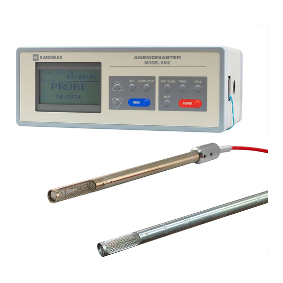
1. Getting Started 1. Getting Started 1.1 Part Names and Functions (1) ····· Main Unit Unit: mm [Front] Display Operation Graphic LCD Sheet Key Pad [Bottom] Probe Board Storing Area Battery Compartment Sizes C Batteries ··· 6 pcs 1.800.561.8187 information@itm.com www. - Page 8 1. Getting Started [Right Side] Probe Connection [Left Side] Backlight Switch Turn this ON to make the LCD screen be backlit so that you can see the screen clearer even in a dark place. Digital Output Terminal * Turn the backlight on only at the time of need in order to prevent battery drain.
-
Page 9: Part Names And Functions (2)
1. Getting Started 1.2 Part Names and Functions (2) ····· Probe [Probe for Medium Temperature] --- MODEL 0203 [Probe for High Temperature] --- MODEL 0204 [Probe for High Temperature] --- MODEL 0205 2300 34.5 10000 1.800.561.8187 information@itm.com www. .com... -
Page 10: Sheet Key Description
1. Getting Started 1.3 Sheet Key Description POWER Turn ON/OFF the power. HOLD Hold the reading and release to hold the reading. PRINT After holding the display screen, press PRINT key to output the hardcopy of the displayed screen via external printer. FAST/SLOW The instrument can be switched into FAST, SLOW1 or SLOW 2. -
Page 11: Power Source
1. Getting Started 1.4 Power Source 1.4.1 Battery Replacement 1. How to Open the Battery Cover 2. How to Remove the Batteries Pull the tape up. Push the click up towards the arrow direction to remove the lid. 3. How to Install Batteries * Insert the middle batteries at last after placing the batteries at the both sides. -
Page 12: Getting Ready For Measurement
1. Getting Started 1.5 Getting Ready for Measurement 1.5.1 Connecting a Probe Probe is calibrated together with the provided connection cable. Please make sure the connection cable is connected when Connection Cable performing a measurement. (heat-resistant: 80 °C) * To change the length of a connection cable, recalibration will be required. -
Page 13: Display Screen - Monitor Screen
1. Getting Started 1.5.4 Display Screen – Monitor Screen Power ON When probe is not connected 08.07.15 FAST VER. 1.0 10:26:40 This will be displayed for 2 sec. KANOMAX PROBE ANEMOMASTER 40-0001 Date ····· Year. Month. Date 08.07.15 FAST Use FAST/SLOW key Time(24-hour display) ·····... -
Page 14: Basic Operation
2. Basic Operation 2. Basic Operation 2.1 How to Hold Reading Front Side Side Surface REMOTE terminal HOLD key Same function Display Procedure 08.07.01 FAST HOLD Press HOLD key. 10:26:40 5.38 m/s When the reading is hold. 25.7 °C 08.07.01 FAST hold 10:26:40 5.38 m/s... -
Page 15: How To Make The Reading More Readable
2. Basic Operation 2.2 How to Make the Reading More Readable This function is useful when you want to obtain averaged readings as readings were volatile. * This function is not available in Average Value Measurement Mode, Intermittent Operation Measurement Mode and Air Flow Measurement Mode. -
Page 16: How To Display Fluctuation Graph
2. Basic Operation 2.3 How to Display Fluctuation Graph You can monitor velocity fluctuation for 90 seconds. (* This function cannot be used in the calculation mode.) Display Procedure 08.07.01 FAST 10:26:40 ▽ Press ▽ key. ▽ key 5.38 m/s Range: 50, 25, 10, 5, 2, 1 m/s 25.7 ℃... -
Page 17: Remaining Battery Level
2. Basic Operation 2.4 Remaining Battery Level Display Procedure This feature is available only on the monitoring screen or when the instrument is ready for a measurement in the measurement mode (when “ready” is displayed). On other 08.07.01 FAST screens this feature cannot be used. 10:26:40 5.38 m/s BATT... -
Page 18: How To Change Data And Time
2. Basic Operation 2.5 How to Change Data and Time Display Procedure MENU (1) Press MENU key. < MENU > 1.MONITOR (2) Select 5. UTILITY. △, ▽ 2.MEASUREMENT 3.DATA OUTPUT Then press SET key. 4.MEMORY CLEAR 5.UTILITY < UTILITY > (3) Select 1. -
Page 19: Printing Hard Copy Of The Monitor Screen
2. Basic Operation 2.6 Printing Hard Copy of the Monitor Screen 2.6.1 What you need ★ Printer (sold separately) ····· Recommended model is DPU-201GS (Seiko Instruments Inc.) ★ Cable to connect the instrument and a printer (sold separately) 2.6.2 Printer Setting Switch No. -
Page 20: Measurement Mode
3. Measurement Mode 3. Measurement Mode 3.1 How to Measure Average, Max and Min value [Average Mode] AVERAGE DATA (1) DATA (2) DATA (3) DATA (N) Average Value AVE=ΣDATA(N)/N Max & Min Values MAX=DATA(i) MIN=DATA(j) Measurement Time Sampling Time ----- S-TIME (S) × (No. of Data) ----- S-TIME (S) * Data is collected every designated sampling time. - Page 21 3. Measurement Mode [Measurement Condition] S-TIME (S): Set the length of sampling (instantaneous value) time. Configurable sampling time (sec): 1 ~ 6, 10, 12, 15, 20, 30, 40, 50, 60 sec DATA (N): Set how many data to be taken every configured sampling time. Configurable number of data: 1 ~ 6, 10, 12, 15, 20, 30, 40, 50, 60, 100, 120, 150, 180 MEMORY: When YES, data will be stored in the internal memory.
-
Page 22: How To Collect Data At Certain Time Intervals [Interval Mode]
3. Measurement Mode 3.2 How to Collect Data at Certain Time Intervals [Interval Mode] [POINT N] [POINT 1] [POINT 2] DATA (1) (3) ·······(N) DATA (1) DATA (1) (3) ·······(N) (3) ·······(N) S-TIME (S) Time interval until the next sampling starts Time length required to measure at one point Interval Time --- INT (min) S-TIME (S) ×... - Page 23 3. Measurement Mode [Measurement Condition] INT (min): Set how often a measurement to be started. Configurable sampling interval (min): 1 ~ 6, 10, 12, 15, 20, 30, 40, 50, 60, 100, 120, 150, 180 min. * Interval (INT) has to be set longer time than sampling time at each point. POINTS: Set how many points you want to perform a measurement? Configurable number of points: 1 ~ 999 points...
-
Page 24: How To Measure Flow Rate In The Duct [Flow Rate Mode]
3. Measurement Mode 3.3 How to Measure Flow Rate in the Duct [Flow Rate Mode] FLOW RATE Measuring Point (POINT) Measurement Example POINT 1 --- AVE 1 = Σ DATA (N)/N POINT 2 --- AVE 2 =Σ DATA (N)/N Average Air Velocity Duct Area (AVE1+AVE2+···AVE N) POINT M --- AVE M =Σ... - Page 25 3. Measurement Mode [Measurement Condition] POINTS: Set how many points to perform a measurement to find average air velocity? Configurable number of partitions: 1 ~ 100 points AREA(m²): Duct’s cross section area (Effective Area) Configurable area size: 0.001∼9.999m² * For S-TIME(S), DATA(N), MEMORY, PRINT, refer to page 15 describing the average measurement.
-
Page 26: Program Set
3. Measurement Mode 3.4 Program Set 3.4.1 How to Pre-set Measurement Mode If a measurement mode is preset, the instrument will enter the measurement standby when you turn it on. To start a measurement, you only need to press START/STOP key. Measurement Condition Measurement Mode <AVE>... -
Page 27: Other Calculation Mode Cannot Be Used
3. Measurement Mode 3.4.2 Other Measurement Mode Cannot be Used When a measurement mode is set, only the configured mode can be used. Even if you select 2. MEASUREMENT on the menu screen, a screen that allows you to select a measurement mode will not display. In stead you will see the screen that allows you to configure the measurement setting for the set measurement mode. -
Page 28: Memory Capacity
3. Measurement Mode 3.5 Memory Capacity Measurement data is stored per page. On top of the each page the ★ Measurement data is stored per page. measurement condition is stored. Therefore, the more pages you ★ Make sure to check in which page the save, the less data you can store. -
Page 29: Memory Over" Display
3. Measurement Mode 3.5.1 “Memory Over” Display When “SET OK!” is selected on the measurement setting screen, the instrument determines if there is enough memory capacity. If there is not enough memory capacity left, “MEMORY OVER” will be displayed. Ave. Value Measurement Intermittent Operation Air Flow Measurement Explanation... -
Page 30: Printing Example - Automatic Printing And Hardcopy Of Calculation Result
3. Measurement Mode 3.6 Printing Example – Automatic Printing and Hardcopy of Calculation Result 3.6.1 Automatic Printing Example Average Mode Interval Mode Air Flow Mode Measurement 2008.07.01 10:26 2008.07.01 10:26 2008.07.01 10:26 starting date & time Measurement Mode <AVE> <INT> <FLOW>... -
Page 31: How To Redisplay, Print And Delete Stored Data
4. How to Redisplay, Print and Delete Stored Data 4. How to Redisplay, Print and Delete Stored Data 4.1 How to Redisplay Data You can re-display the stored calculation result. However, each memory data cannot be displayed on the instrument’s display. You need to either output to the printer or transfer data to the computer via digital output (RS-232C) Display Procedure... -
Page 32: How To Output Data To Printer
4. How to Redisplay, Print and Delete Stored Data 4.2 How to Output Data to Printer 4.2.1 Procedure for outputting data to a printer Display Procedure MENU (1) Press MENU key. < MENU > 1. MONITOR (2) Select 3.DATA OUTPUT. △, ▽... - Page 33 4. How to Redisplay, Print and Delete Stored Data 1. START P:005 (8) Move the cursor to 3. SET OK! 2. END P:007 3. SET OK! Press SET key. < FORMAT > 1. RESULT △, ▽ (9) Select the item to be output. 2.
-
Page 34: Deleting Memory Data
4. How to Redisplay, Print and Delete Stored Data 4.3 Deleting Memory Data ALL CLEAR CLEAR P001 P001 P002 P002 P003 Deleting partially P003 Deleting All P004 · · P005 · · · · · · Page * The page number will be moved up. P036 [Example] When deleting from P003 to P005,... -
Page 35: Deleting Selected Pages Only
4. How to Redisplay, Print and Delete Stored Data 4.3.2 Deleting Selected Pages Only Display Procedure MENU (1) Press MENU key. < MENU > 1. MONITOR (2) Select 4. MEMORY CLEAR. 2. MEASUREMENT △, ▽ 3. DATA OUTPUT Then press SET key. 4. -
Page 36: Data Output
5. Data Output 5. Data Output 5.1 Analog Output Output on the measurement screen -------------------------------------- ★ To be output every 0.25 second ★ Output Voltage: DC0 ~ 1V Initial Screen: Except when the screen is on hold ★ Output Impedance: 47Ω Measurement Mode: Except when the calculation result is displayed or the instrument is waiting for the next sampling... - Page 37 5. Data Output < RANGE > (a) The range highlighted is the current set range. 5 m/s If there is no change to be made, press SET key. 2. 0 25 m/s The screen will go back to the ANALOG OUTPUT screen (a). 3.
-
Page 38: Digital Output (Rs-232C)
5. Data Output 5.2 Digital Output (RS-232C) Output Format Baud Rate: 4800, 1200 Word Length: 8 bit Parity Bit: None Stop Bit: 1 bit 5.2.1 Connection Example Wire Anemomaster (MODEL 6162) Signal Name Connection Pin No. Signal Name Signal Meaning Signal Direction Signal Line Color Signal Ground... -
Page 39: To Transfer Raw Data (Measurement Data Per Second)
5. Data Output 5.2.3 To Transfer Raw Data (measurement data per second) When transferring data, make sure to display the monitor screen. While transferring data, do not use other functions. 08.07.01 FAST When SLOW is indicated, moving average 10:26:40 deviations will be transferred. 12.8 m/s Please switch to monitoring screen. -
Page 40: To Transfer Memory Data (Measurement Data Stored In Memory)
5. Data Output 5.2.4 To Transfer Memory Data (Measurement Data Stored in Memory) DATA OUTPUT mode in menu screen Internal Memory Getting Ready for Transferring Memory Data Display Procedure MENU (1) Press MENU key. < MENU > 1. MONITOR 2. MEASUREMENT (2) Select 3. - Page 41 5. Data Output Output Format of Measurement Condition ----- M Command : 25 Characters # # ; # # # ; # # ; # # # ; # # # ; # # # # # CRLF (1) Measurement Mode (VI: Air Velocity & Air Temperature) Calculation Mode (AVE: Average Measurement INT: Interval Measurement FLW: Flow Measurement) (3) S-TIME (S) (Sampling Time)
-
Page 42: Main Specification
6. Main Specification 6. Main Specification Specification (1) Model Name Main Unit: Model 6162 Probe: Model 0203 (for mid temperature) Model 0204 (for high temperature) Model 0205 (for high temperature) (2) Measurement Feature Air velocity and air temperature (simultaneous measurement) (3) Measurement Object Clean air under normal pressure and normal temperature (4) Measurement Range... - Page 43 6. Main Specification General Specification (12) Power Source Power Supply Voltage DC 9V (2A) Dry Cell: six (6) size C batteries (Alkaline Cell, Manganese Cell) AC Adapter: (100 240VAC 50 60Hz /0.2A) Power Consumption Max 5.6 VA (13) Battery Life Approx.
-
Page 44: Measurement Principle
7. Measurement Principle 7. Measurement Principle 7.1 Principle of Hot-Wire Anemometer When the heated air velocity sensor is exposed to airflow, the sensor will be cooled. As the sensor temperature changes, the residence value changes accordingly. The faster the velocity is, the greater the residence value changes. Therefore, if how air velocity is proportional to the residence value is understood, air velocity can be calculated using the measured residence value (or electric current). -
Page 45: Temperature Compensation
7. Measurement Principle 7.2 Temperature Compensation When the air temperature changes, the amount of heat dissipation changes accordingly even when the air velocity is constant. By providing a temperature measurement sensor Rc having the same temperature coefficient as the air velocity at the opposite side of the bridge, the constant <... -
Page 46: Influence By Gas Composition To Be Measured
7. Measurement Principle 7.3 Influence by Gas Composition to be Measured Hot-wire Anemometers indicate air velocity based on the amount of radiation heat which is the heat quantity deprived from the sensor to fluid. Depending on the fluid to be measured, the amount of radiation heat varies, and the air velocity reading, too, will be affected. - Page 47 7. Measurement Principle Heat diffusion quantity can be found by; πλ − ········ (1) Q: Heat diffusion quantity : Nussselt number π:Circle ratio λ:Thermal conductivity L: Length of cylinder T: Heating body temp. :Gaseous temperature In order to obtain the property value of mixed gas, obtain the property value of each component. Based on the mixing ratio, the property value of the mixture can be found.
-
Page 48: Troubleshooting
8. Troubleshooting 8. Troubleshooting * Before you send the unit for repairs, please check the followings once again. 8.1 Checking Power Source Symptom Possible Cause / Solution Refer to - The batteries may be drained. Even when your turn the power Page 5 switch ON, nothing is displayed. -
Page 49: During A Measurement
8. Troubleshooting 8.3 During a Measurement Symptom Possible Cause / Solution Refer to The displayed measurement value is - If a measurement is performed out of the spec abnormal. range, “over” will be displayed on the screen. Air Velocity: **.* - Probe sensor may be damaged. -
Page 50: Warranty And After-Sales Service
9. Warranty and After-sales Service KANOMAX Limited Warranty The limited warranty set below is given by KANOMAX with respect to the KANOMAX brand Anemomaster Model 6162, its attachment parts including Probe and other accessories (hereafter referred to as “PRODUCT”) that you have purchased. - Page 51 If the PRODUCT is malfunctioning, please check with “Troubleshooting” to find possible cause first. Repair parts are retained for a minimum period of five (5) years after production cessation of the PRODUCT. This storage period of repair parts is considered as the period during which KANOMAX can provide repair service.
-
Page 52: Contact Information
10. Contact Information 10. Contact Information JAPAN & ASIA KANOMAX JAPAN INC. 2-1 Shimizu, Suita City, Osaka, 565-0805, Japan TEL: 81-6-6877-0183 FAX: 81-6-6879-5570 URL: http://www.kanomax.co.jp/ E-Mail: sales@kanomax.co.jp USA & EUROPE KANOMAX USA INC. PO Box 372, 219 Hwy. Route 206, Andover, NJ 07821, U.S.A.
Need help?
Do you have a question about the Anemomaster 6162 and is the answer not in the manual?
Questions and answers