
Related Manuals for MOTECK MK35


Summary of Contents for MOTECK MK35
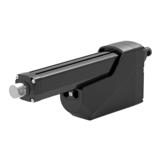
- Page 1 Actuator MK35 2023.7_V2.2 Revision Technical changes may be made to improve the product without notice!...
-
Page 2: Table Of Contents
1. General __________________________________________ 2. Important Information ___________________________ 3. Installation 3.1 Product label ___________________________________ 3.2 Terminology ____________________________________ 3.3 Working environment ____________________________ 3.4 Mechanical installation ___________________________ 3.5 Electrical installation _____________________________ 3.6 Installation and operation of control options ___________ 4. CAN Bus SAE J1939 Protocol 4.1 Summary... -
Page 3: General
1. General 1.1 About the manual This manual is the mechanical and electrical installation instructions of MK35 electric linear actuator, and also includes performance data and details of the optional specifications. Please read the instructions carefully before installing the actuator. The installation work must be performed by qualified personnel, which is very important. -
Page 4: Important Information
2. Important Information ● Only qualified personnel are allowed to carry out the mechanical and elec- trical installation of this product. Qualified personnel should be familiar with the mechanical or electrical installation work and have corresponding work qualifications. ●... -
Page 5: Installation
The product label is located on the side of the outer tube. It tells you the actuator model and basic specifi- cation. Before performing any installation or maintenance on the actuator, please check the product label to determine the actuator type. If you need any help from MOTECK, please provide the serial number and actuator model. -
Page 6: Mechanical Installation
3.4 Mechanical installation 3.4.1 Safety notes ● Do not perform mechanical installation when the actuator is powered. ● Complete the mechanical installation properly before proceeding to the electrical installation steps. 3.4.2 Basic installation considerations (1) Always use only the holes of the front and rear connectors to install the actuator. First check the model number on the product label (section 3.1), and then refer to the model coding (section 6.2) to identify the... - Page 7 3.4.3 Force and orientation (1) The actuator can be installed in any orientation and can withstand push and pull loads. (2) When installing the actuator, make ensure that the force of the load acts on the central axis of the extension tube and rear connector.
- Page 8 3.4.5 Installation and operation of hand crank (1) When installing the actuator, please make sure that there is enough space between the rear connector and any objects behind it so that the hand crank can be operated. (2) Please use a flat-head screwdriver to remove the cover and connect with a 6mm hexagon socket.
-
Page 9: Electrical Installation
● It is forbidden to use Pulse Width Modulation (PWM) as input power to MK35, otherwise it will cause malfunction and cause permanent damage. 3.5.3 Fuse specification Install a slow-blow fuse of this specification between the actuator and the power supply for protection. - Page 10 To avoid malfunctions caused by voltage drop, the cross-section of the power cable wire must be large enough. The cross-section of the MK35 power cable wire is 2.0mm² (14AWG) and the maximum length is 3 meters. If the customer must connect an extension cord, the wire requirements of the extension cord are as follows.
-
Page 11: Installation And Operation Of Control Options
3.6.1 Determine control options MK35 actuator is equipped with one of the control options in the table below. Please check the model number on the product label (section 3.1), and then refer to the model coding (section 6.2) to identify the control options of the actuator. - Page 12 (2) Do not adjust the input voltage in an attempt to control the speed of the MK35 DXX control options. (3) The D00 option does not include a signal cable, and the port has a waterproof cap.
- Page 13 3.6.3 Control option D0L (DC control, with EoS signal output) In addition to all the functions included in the D00 option (section 3.6.2), the D0L option is also with an arrival signal output when it reaches the end of stroke (EoS), so that the customer system can perform corresponding control, such as light signal display, relay action, etc.
- Page 14 3.6.4 Control option DPL (DC control, with EoS signal output and potentiometer positioning output) In addition to all the functions included in the D00 and D0L options (section 3.6.2 & 3.6.3), the DPL option is also equipped with a potentiometer, which allows the user's control device to know the absolute position of the actuator at any time, and can be used to determine the speed and direction of the actuator's movement.
- Page 15 ● Wire definitions: DPL Wire color Definition Description Connect red wire to “Vdc +” & black wire to “Vdc -“ of DC power to Power extend the actuator. Switch the polarity of DC input to retract it. cable Black...
- Page 16 3.6.5 Control option DHL (DC control, with EoS signal output and dual Hall effect sensors feedback-NPN type) In addition to all the functions of the D00 and D0L options (section 3.6.2 & 3.6.3), the DHL option is also equipped with dual Hall effect sensors, providing an NPN-type feedback circuit.
- Page 17 ● Wire definitions: DHL Wire color Definition Description Connect red wire to “Vdc +” & black wire to “Vdc -“ of DC power to Power extend the actuator. Switch the polarity of DC input to retract it. cable Input voltage: According to actuator voltage specification...
- Page 18 3.6.6 Control option D+L (DC control, with EoS signal output and dual Hall effect sensors feedback-PNP type) In addition to all the functions of the D00 and D0L options (section 3.6.2 & 3.6.3), the D+L option is also equipped with dual Hall effect sensors, providing an PNP-type feedback circuit.
- Page 19 ● Wire definitions: D+L Wire color Definition Description Connect red wire to “Vdc +” & black wire to “Vdc -“ of DC power to Power extend the actuator. Switch the polarity of DC input to retract it. cable Input voltage: According to actuator voltage specification...
- Page 20 ● It is forbidden to adjust the input voltage in an attempt to control the speed of the MK35 SXX control options. The battery or full-wave rectified DC power used must be within acceptable voltage range, otherwise the actuator will stop operating.
- Page 21 ● Wire definitions: S0L Wire color Definition Description Connect Red to positive. Connect Black to negative. Power cable Do not swap the polarity. Black Input voltage: 9~16V @12V DC; 18~32V @24V DC Actuator extends Connect Red to positive (V+) to extend, input current <10mA...
- Page 22 3.6.8 Control option SPL (Low current signal control, with EoS signal output and potentiometer positioning output) In addition to all the functions included in the S0L option (section 3.6.7), the SPL option is also equipped with a potentiometer, which allows the user's control device to know the absolute position of the actuator at any time, and can be used to determine the speed and direction of the actuator's movement.
- Page 23 ● Wire definitions: SPL Wire color Definition Description Connect Red to positive. Power Connect Black to negative. cable Do not swap the polarity. Black Input voltage: 9~16V @12V DC; 18~32V @24V DC Actuator extends Connect Red to positive (V+) to extend, input current <10mA...
- Page 24 3.6.9 Control option SHL (Low current signal control, with EoS signal output and dual Hall effect sensors feedback-NPN type) In addition to all the functions of the S0L option (section 3.6.7), the SHL option is also equipped with dual Hall effect sensors.
- Page 25 ● Wire definitions: SHL Wire color Definition Description Connect Red to positive. Power Connect Black to negative. cable Do not swap the polarity. Black Input voltage: 9~16V @12V DC; 18~32V @24V DC Actuator extends Connect Red to positive (V+) to extend, input current <10mA...
- Page 26 CAN High 120Ω 120Ω CAN Low Remarks: • The max. length of the CAN Bus wiring harness is 40m. • The max. length of the stub (the yellow and blue wires from MK35 actuator connected to the Bus) is 3m.
- Page 27 ● Wiring: J00 Fuse Off-Bus extending Off-Bus retracting CAN High CAN Low Not used Not used Not used Remarks: All dashed lines are connected by the customer. ● Wire definitions: J00 Wire color Definition Description Connect Red to positive.
-
Page 28: Can Bus Sae J1939 Protocol 4.1 Summary
4.2.1 J1939 NAME The J1939 NAME is a 8 Byte (64 bit) data provided by MOTECK for identification and arbitration of the controller application(Hereinafter referred to as CA) on the network *. The 64 bit value is composed of 10 parameters. - Page 29 4.2.2.2 Hardware address selection If multiple MK35 actuators will be used in a CAN Bus network, in order to save initialization time, MK35 has a DIP switch for address selection. Up to 16 MK35 actuators can be connected and preset addresses.
-
Page 30: Command And Status Feedback
All CAs in the bus system can use the motion commands and parameters in the following table that comply with the J1939 communication protocol to control MK35 actuators or receive status feedback through the two signal lines of the CAN network system. - Page 31 Not used. (suggest 0 or 255) Remarks: (1) If the error code of overcurrent or voltage error is not cleared, MK35 will not respond to the next command. Other types of error codes will be automatically cleared after the actuator stops moving.
- Page 32 4.3.2 Proprietary B message MK35 will report Proprietary B messages in response to control or setting commands (Proprietary A) sent by CA in the same network. The requirements are as follows: (1) Transmission rate: 250 Kbps (2) Protocol Data Unit (PDU):...
- Page 33 The error flag turns on "value 1". Default= 0. If the position feedback remains unchanged while the actuator is moving, the protection will be activated to stop Please contact Moteck sales for information. Position error the actuator. The error flag will turn on "value 1".
-
Page 34: Troubleshooting
5. Troubleshooting Troubles Possible Causes Solution Guide The actuator does not move and The actuator is not getting the Make sure to provide the correct makes no sound. correct input voltage range. input voltage for the actuator. The actuator hummed and did not... -
Page 35: Performance And Options
6. Performance and Options 6.1 Performance data Typical speed (mm/s) Typical current (A) Motor & Push / Pull Spindle Gear ratio Duty cycle No load Full load Max. (N) No load Full load code 1,700 18.0 ❶ 10:1 2,600 18.0... -
Page 36: Ordering Key
6.2 Ordering key MK35 - XXXX 12:12V DC Input voltage 24:24V DC Motor and G5B:4500rpm / 5mm pitch / Ball screw spindle type 05:5:1 20:20:1 10:10:1 30:30:1 Gear ratio 15:15:1 XXXX:0100~1000mm (one step in every 50mm) Stroke :DC control, without positioning feedback.
Need help?
Do you have a question about the MK35 and is the answer not in the manual?
Questions and answers