
Related Manuals for MOTECK MK35


Summary of Contents for MOTECK MK35
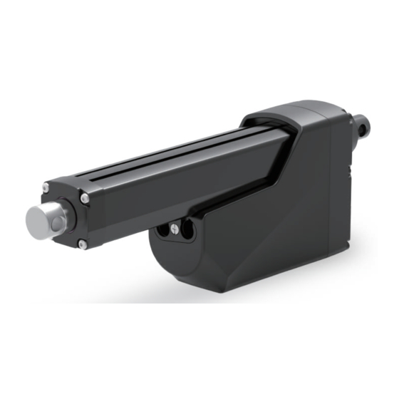
- Page 1 Actuator MK35 2022.5_V1.0 Revision Technical changes may be made to improve the product without notice!...
-
Page 2: Table Of Contents
1. General __________________________________________ 2. Important Information ___________________________ 3. Installation 3.1 Product label ___________________________________ 3.2 Terminology ____________________________________ 3.3 Working environment ____________________________ 3.4 Mechanical installation ___________________________ 3.5 Electrical installation _____________________________ 3.6 Installation and operation of control options ___________ 4. CAN Bus SAE J1939 Protocol 4.1 Summary... -
Page 3: General
1. General 1.1 About the manual This manual is the mechanical and electrical installation instructions of MK35 electric linear actuator, and also includes performance data and details of the optional specifications. Please read the instructions carefully before installing the actuator. The installation work must be performed by qualified personnel, which is very important. -
Page 4: Important Information
2. Important Information ● Only qualified personnel are allowed to carry out the mechanical and elec- trical installation of this product. Qualified personnel should be familiar with the mechanical or electrical installation work and have corresponding work qualifications. ●... -
Page 5: Installation
The product label is located on the side of the outer tube. It tells you the actuator model and basic specification. Before performing any installation or maintenance on the actuator, please check the product label to determine the actuator type. If you need any help from MOTECK, please provide the serial number and actuator model. -
Page 6: Mechanical Installation
3.4 Mechanical installation 3.4.1 Safety notes ● Do not perform mechanical installation when the actuator is powered. ● Complete the mechanical installation properly before proceeding to the electrical installation steps. 3.4.2 Basic installation considerations (1) Always use only the holes of the front and rear connectors to install the actuator. First check the model number on the product label (section 3.1), and then refer to the model coding (section 6.2) to identify the... - Page 7 3.4.3 Force and orientation (1) The actuator can be installed in any orientation and can withstand push and pull loads. (2) When installing the actuator, make ensure that the force of the load acts on the central axis of the extension tube and rear connector.
- Page 8 3.4.5 Installation and operation of hand crank (1) When installing the actuator, please make sure that there is enough space between the rear connector and any objects behind it so that the hand crank can be operated. (2) Please use a flat-head screwdriver to remove the cover and connect with a 6mm hexagon socket.
-
Page 9: Electrical Installation
3.5 Electrical installation 3.5.1 Safety notes ● If users extend the power cord, Make sure that your own power extension cord can withstand the maximum operating current of the actuator. ● It is recommended to install an emergency stop switch at a suitable location of the power supply line. -
Page 10: Installation And Operation Of Control Options
3.6.1 Input voltage It is forbidden to adjust the input voltage in an attempt to control the speed of the MK35 actuator. The battery or full-wave rectified DC power used must be within acceptable voltage range, otherwise the actuator will stop operating. - Page 11 3.6.3 Control option S0L (signal control, with EoS signal output) Option S0L uses a low current (<10mA) input signal to control the extension, retraction or stop of the actuator, without switching the polarity of the input DC power, and there is an arrival signal output when it reaches the end of stroke (EoS).
- Page 12 3.6.4 Control option SPL (signal control, with EoS signal output and potentiometer positioning output) In addition to all the functions included in the S0L option (section 3.6.3), the SPL option is also equipped with a potentiometer, which allows the user's control device to know the absolute position of the actuator at any time, and can be used to determine the speed and direction of the actuator's movement.
- Page 13 Wire definitions: SPL Wire color Definition Description Connect Red to positive. Power Connect Black to negative. cable Do not swap the polarity. Black Input voltage: 12/24V±20% Connect Red to positive (same as V+) to extend. Actuator extends Vin= 5~32V Connect Black to positive (same as V+) to extend.
- Page 14 In addition to all the functions of the S0L option (section 3.6.4), the SHL option is also equipped with dual Hall effect sensors. The Hall feedback is a relative positioning. And each MK35 actuator has been pre-calibrated before it is completed and shipped. Although the position...
- Page 15 Wire definitions: SHL Wire color Definition Description Connect Red to positive. Power Connect Black to negative. cable Do not swap the polarity. Black Input voltage: 12/24V±20% Connect Red to positive (same as V+) to extend. Actuator extends Vin= 5~32V Connect Black to positive (same as V+) to extend.
- Page 16 J1939 local area network control system to apply this actuator. 3.6.6.1 Preparation Provide an individual power supply for MK35 actuator, separate from the power supply of the CAN Bus system (if this power supply exists). All command and feedback message of the J00 option, including protection message, are processed through CAN messages transmitted by the signal cable.
- Page 17 The actuator may need to be operated offline (via the CAN Bus network) for repair, maintenance and testing. Please unplug the CAN High / Low signal cable from MK35, and then plug in another signal cable for offline operation (this signal cable is not included and needs to be ordered separately).
-
Page 18: Can Bus Sae J1939 Protocol 4.1 Summary
The content in this chapter assumes that the reader is familiar with the SAE J1939 standard. Therefore, the terminology in the standard is used, but not described in detail. MOTECK provides command information to control the actions and status feedback of MK35 actuator, which complies with the following J1939 standards PGN. - Page 19 4.2.2.2 Change address from Hardware If multiple MK35 actuators will be used in a CAN Bus network, in order to save initialization time, MK35 has a DIP switch for address selection. Up to 16 MK35 actuators can be connected and preset addresses.
-
Page 20: Command And Status Feedback
• Error code 4.3.1 Proprietary A All control application (CA) in the same network can send actions or setting command to MK35 through Proprietary A. The parameters of all control parameters can be adjusted by Proprietary A. The requirements are as... - Page 21 Not used. (suggest 0 or 255) Remarks: (1) If the error code of overcurrent or voltage error is not cleared, MK35 will not respond to the next command. Other types of error codes will be automatically cleared after the actuator stops moving.
- Page 22 4.3.2 Proprietary B MK35 will return Proprietary B messages in response to control or setting commands (Proprietary A) sent by control applications (i.e. ECU) in the same network. The requirements are as follows: (1) Transmission rate: 250 Kbps (2) Protocol Data Unit (PDU):...
- Page 23 300ms, the protection is activated to stop the actuator. The error flag turns on "value 1". Default= 0. When the input voltage exceeds the allowable Please contact Moteck sales for information. Voltage error working range, i.e. 18~32V, the protection function will be activated to stop the actuator.
-
Page 24: Troubleshooting
5. Troubleshooting Troubles Possible Causes Solution Guide The actuator does not move and The actuator is not getting the Make sure to provide the correct makes no sound. correct input voltage range. input voltage for the actuator. The actuator hummed and did not... -
Page 25: Performance And Options
6. Performance and Options 6.1 Performance data Typical Speed (mm/s) Typical Current (A) Push / Pull Gear ratio Duty Cycle No load Full load Max. (N) No load Full load 10:1 2,600 15:1 4,500 20:1 6,800 30:1 10,000 Speed vs. Load Current vs. -
Page 26: Ordering Key
6.2 Ordering key MK35 - XXXX 12: 12V DC Input voltage 24: 24V DC Motor code G: 4500rpm 10: Gear ratio 10:1 15: Gear ratio 15:1 Gear type 20: Gear ratio 20:1 30: Gear ratio 30:1 Spindle type B: Ball Screw...
Need help?
Do you have a question about the MK35 and is the answer not in the manual?
Questions and answers