Table of Contents
Advertisement
Quick Links
User Guide
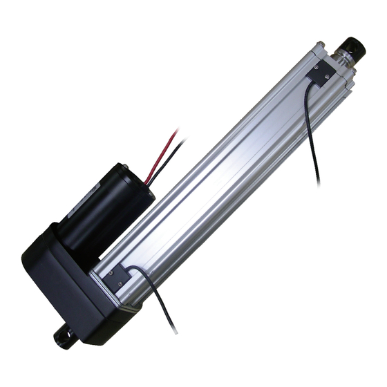
Industrial Actuator
CAUTION
CAUTION
:
:
WIRE CONNECTION
WIRE CONNECTION
For ID12 actuators, connection rule of power wires varies according to different types and gear ratio(s).
Please follow the instructions below.
Standard Type
With Limit Switch Type
KG
Load
KG
Side Load
Please refer to the table below to define the actuator's extension.
Red and Black is the color of wires, M+ is "+" and M- is "-" of DC power.
Please refer to the table below to define the actuator's extension.
When Red (M+) is connected to "+" and Black (M-) is connected to "-" of
DC power the actuator will extend.
Model: ID12
External adjustable reed sensor
NC type (normal close)
The load should be centered on the operating direction.
Side Load is NO good for actuators.
Gear Ratio
5:1,10:1, 20:1
30:1, 40:1
Wiring
Red
Black
MOTORIZE OUR WORLD
Wiring
Red
M+
Black
M-
Red
M-
Black
M+
M+
M-
R
Advertisement
Table of Contents

Related Manuals for MOTECK ID12


Summary of Contents for MOTECK ID12
- Page 1 Side Load WIRE CONNECTION WIRE CONNECTION For ID12 actuators, connection rule of power wires varies according to different types and gear ratio(s). Please follow the instructions below. Standard Type Please refer to the table below to define the actuator's extension.
- Page 2 2016 Moteck. Printed in Taiwan. The contents of this publication are the copyright of the publisher and may not be copied or even extracted unless prior written permission is authorized.
Need help?
Do you have a question about the ID12 and is the answer not in the manual?
Questions and answers