
Related Manuals for MOTECK ID10 Series


Summary of Contents for MOTECK ID10 Series
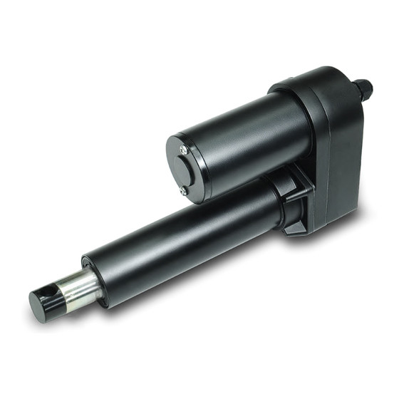
- Page 1 Actuator ID10 series 2024.08_V3.0 Revision Technical changes may be made to improve the product without notice!...
-
Page 2: Table Of Contents
_____________________________ 1. Important Information ________________________________________ 2. Installation _____________________________________ 2.1 Terminology ____________________________ 2.2 Mechanical installation ________________________________ 3. Restraining Torque __________________________ 4. Manual Drive Connector __________________________ 5. Wiring with Flying Leads __________________________________________ 5.1 ID10 _________________________________________ 5.2 ID10BT _________________________________________ 5.3 ID10G _________________________________________ 5.4 ID10K... -
Page 3: Important Information
1. Important Information ● Only qualified personnel are allowed to carry out the mechanical and electrical installation of this product. Qualified personnel should be familiar with the mechanical or electrical installation work and have corresponding work qualifications. ● Do not perform mechanical installation when the actuator is powered. -
Page 4: Installation
2. Installation Terminology Outer tube Extension tube Front connector Rear connector Power cable 2.2 Mechanical installation (1) Be sure that the load acts on the actuator in the axial direction and it isn't recommended to apply side load to the actuator. -
Page 5: Restraining Torque
3. Restraining Torque ● If the actuator needs to be test run before being installed on the operating frame, the front and rear connectors must be fixed first to limit the rotation of the extension tube. The torque is very large. If the front and rear connectors are not fixed, the extension tube (or the actuator) will rotate instead of moving. -
Page 6: Wiring With Flying Leads
Wiring with Flying Leads ID10 For ID10 actuator, connection rule of power wires varies according to different types and gear ratio(s). Please follow the instructions below. (1) Basic (Without limit switch nor positioning feedback) ● Gear ratio: 5:1, 10:1, 20:1... - Page 7 (4) With Potentiometer (POT) absolute positioning feedback Wire color Definition Descriptions Connect red wire to “Vdc +” & black wire to “Vdc -“ of DC power to Power DC power wires extend the actuator. Switch the polarity of DC input to retract it.
-
Page 8: Id10Bt
ID10BT (1) Basic (Without positioning feedback) Wire color Definition Descriptions Connect red wire to “Vdc +” & black wire to “Vdc -“ of DC power to Power DC power wires extend the actuator. Switch the polarity of DC input to retract it. -
Page 9: Id10G
ID10G (1) Basic, with limit switches. Wire color Definition Descriptions Descriptions Connect red wire to “Vdc +” & black wire to “Vdc -“ of DC power to Power DC power wires extend the actuator. Switch the polarity of DC input to retract it. - Page 10 (3) With Potentiometer (POT) absolute positioning feedback Wire color Definition Descriptions Connect red wire to “Vdc +” & black wire to “Vdc -“ of DC power to Power DC power wires extend the actuator. Switch the polarity of DC input to retract it.
-
Page 11: Id10K
ID10K For ID10K actuator, connection rule of power wires varies according to different types and gear ratio(s). Please follow the instructions below. (1) Basic (Without limit switch nor positioning feedback) ● Gear ratio: 20:1 Wire color Definition Descriptions Connect red wire to “Vdc +” & black wire to “Vdc -“ of DC power to... - Page 12 (4) With Potentiometer (POT) absolute positioning feedback Wire color Definition Descriptions Connect red wire to “Vdc +” & black wire to “Vdc -“ of DC power to Power DC power wires extend the actuator. Switch the polarity of DC input to retract it.
-
Page 13: Id10P
Terms of Use The user is responsible for the suitability of MOTECK products, and the products listed on the MOTECK website are subject to change without notice. MOTECK reserves the right to terminate sales or delete any products displayed on the website or listed in its catalog.
Need help?
Do you have a question about the ID10 Series and is the answer not in the manual?
Questions and answers