Hach SC4500 User Manual
Profinet and ethernet/ip modules
Hide thumbs
Also See for SC4500:
- User manual ,
- Basic user manual (564 pages) ,
- User instructions (292 pages)
Table of Contents
Advertisement
Advertisement
Table of Contents

Related Manuals for Hach SC4500


Summary of Contents for Hach SC4500
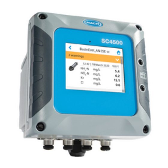
- Page 1 DOC343.52.90752 PROFINET and EtherNet/IP modules 11/2021, Edition 2 User manual...
-
Page 3: Table Of Contents
Table of Contents Section 1 General information ................3 1.1 Safety information ....................3 1.2 Use of hazard information ..................3 1.3 Product overview ....................3 Section 2 Commissioning checklist ............... 5 Section 3 Installation ....................5 3.1 Install the module ....................5 3.2 Electrical installation ..................... - Page 4 Table of Contents...
-
Page 5: Section 1 General Information
• PROFINET module—The controller can connect to a PLC through the Industrial Ethernet Protocol, which includes a PROFINET solution. Line, Star and Ring topologies are available. The SC4500 controller PROFINET and EtherNet/IP modules are applicable to the network topologies that follow: •... - Page 6 Figure 1 Chain topology Figure 2 Star topology Figure 3 Ring topology 4 English...
-
Page 7: Section 2 Commissioning Checklist
Section 2 Commissioning checklist Use the checklist that follows to complete the PROFINET or EtherNet/IP installation and configuration procedure. Do the tasks in the order given. Task Completed Install the module on page 5 in the controller. Electrical installation on page 7—Make all of the necessary hardware connection (wiring). - Page 8 Figure 4 EtherNet/IP or PROFINET module slot 1 Module slot Configure the controller with 1 or 2 Industrial Ethernet ports based on the network configuration. For star topologies, configure the controllers with 1 Ethernet port. Refer to Figure 5. For chain or ring topologies, configure the controller with 2 Ethernet ports.
-
Page 9: Electrical Installation
CAT 5, 5E, CAT 6, 6A or CAT 7 category cables. The cables have an IP66 M12 connector or IP20 RJ45 connector. Hach supplies two standard cable accessories and a kit that includes the connectors to make a custom cable. Refer to Replacement parts and accessories on page 43. -
Page 10: Section 4 Startup
Figure 7 Wiring example 1 PLC 3 SC4500 controller 2 Industrial switch 4 Laptop Section 4 Startup 1. Supply power to the controller and PLC. 2. Set the PLC to on. Section 5 Operation 5.1 Configure the Ethernet ports Make sure that the Ethernet port configuration in the controller is set to one of the IEP (industrial Ethernet ports) options. -
Page 11: Install The Configuration File
3. Select the file, then click Install. When the file is installed, "SC4500 Controller 1 port" and "SC4500 Controller 2 port" are available in the PLC hardware catalog view. Select OTHER FIELD DEVICES > PROFINET IO > IO > HACH LANGE >... -
Page 12: Install The Ethernet/Ip Eds File
3. In the wizard, select the option Register and EDS file(s). Then, select Register a single file and browse the downloaded ESD file. 4. Complete the Wizard instructions. When the file is installed, the SC4500 module is available in the Controller organizer view. 10 English... -
Page 13: Configure The Plc Environment
1. Add all of the items that configure the network topology from the Catalog devices. In the example: the PLC, industrial switch and SC4500 controller. 2. Select Catalog > Other field devices > PROFINET IO > I/O > Hach Lange > Hach SC4500 controller. The PROFINET catalog shows two SC4500 controller modules. Select the module based on the Ethernet port configured option: 1 port (MIX IEP) or 2 ports (IEP only). - Page 14 4. Assign the SC4500 controller to the PLC on the Network overview. 5. On the Online and Diagnostic view, select Assign IP address to set the IP address of the SC4500 controller. 12 English...
- Page 15 6. Select the commands Compile and Download to device on the PLC menu. The SC4500 controller gets the assigned IP address and the Industrial Ethernet Interface web page is enabled. The Industrial Ethernet Interface web page gives information about the data sent through Telegram.
- Page 16 10. On the SC4500 controller, go to the main menu. Then, select OUTPUTS > PROFINET > SIMULATION. Set the simulation to ON. The controller starts sending simulation values to the PLC. The controller continuously sends a simulation value in a loop from Minimum to Maximum during the set Period. When the value gets the Maximum set value, it decreases to the minimum and then again to maximum.
- Page 17 12. Select Modules assigned to see the information that the controller sends in simulation mode. 13. Select Telegram composition to see Telegram information on the type of data (integer or float) and their relative address in the PLC memory. English 15...
- Page 18 14. Add the inputs modules on the Device overview tab of the PLC based on the Modules assigned information. 15. Add the tags and variables based on the values that the controller simulation sends. Add the same settings as in the Industrial Ethernet web page. Refer to the table below. Tags Type Size...
-
Page 19: Configure The Ethernet/Ip Environment
5.3.2 Configure the EtherNet/IP environment Configure the EtherNet/IP Studio 5000 Logix Designer environment as follows: 1. On the SC4500 controller, go to the main menu. Then, select OUTPUTS > EtherNet/IP > Adressing mode. Select Static. The option EtherNet/IP shows in the EtherNet/IP menu. - Page 20 3. Select OUTPUTS > EtherNet/IP > Simulation. Set the Simulation to on. The controller starts sending simulation values to the PLC. The controller continuously sends a simulation value in a loop from Minimum to Maximum during the set Period. When the value gets the Maximum set value, it decreases to the minimum and then again to maximum.
- Page 21 6. In the Catalog tab, add "SC4500" to find the controller module. Select the "HACH SC4500 Controllers", then select Create. The New module window shows. 7. In the General section, add a Name (in the example the controller serial number) and Description (optional) to identify the controller in the network.
- Page 22 8. Push on Change to examine the Module definition. The values must agree with the controller simulation values: input size 14 SINT. 9. Go to the Connection section and configure the settings that follow: • Requested Packet Interval (RPI)—Sets the PLC update rate in milliseconds. Range: 1.0 to 3200.0 (Default: 10.0).
- Page 23 11. In a web browser, type the IP address to access the Industrial Ethernet Interface web page. 12. Select Modules assigned to see the information that the controller sends in simulation mode. English 21...
- Page 24 13. Select Telegram composition to see Telegram information on the type of data (integer or float) and the Input Tag suffix. 14. In the Studio 5000 Logix Designer environment, on the Controller organizer tab, select Tasks > Main Task > MainProgram > Parameter and local tags. Add the tags based on the Telegram composition of the simulation.
- Page 25 15. On the Controller organizer tab, select Tasks > Main Task > MainProgram > MainRoutine. For each parameter of the simulation, add a COP module with the data that follow (refer to the table below): • Source—Add the controller name, then the I.Data based on the bytes size. •...
- Page 26 16. Select the option Go Online. 17. Select Download. 24 English...
- Page 27 18. Select Download. 19. On the SC4500 controller, go to the main menu. Select OUTPUTS > EtherNet/IP > Status to examine the connection condition. English 25...
- Page 28 20. Go to Program Parameters and Local Tags. On the bottom of the window, select the tab Monitor tags. If the connection is successful, the simulation data from the SC4500 controller shows. 21. When the simulation is successful, stop the simulation in the controller. In the main menu of the controller, select Outputs >...
-
Page 29: Configure The Module
5.4 Configure the module 5.4.1 Configure the PROFINET module Configure the PROFINET and the Telegram data in the controller to send sensor or device data to the PLC. Refer to PROFINET Telegram composition on page 38. Configure the PROFINET settings as follows: 1. - Page 30 3. On the Telegram menu, select the device. Select Add tags. For this example, the tags that follow are selected: Classified Error, Classified Status 1, Dissolved oxygen [mg/L], Heartbeat and Temperature [ºC] 4. Push OK, then Save. 5. In the PROFINET menu, select Modules assigned. The controller shows the slots information used to configure the TIA environment.
- Page 31 7. Select Modules assigned to see the information that the sensor sends. 8. Select Telegram composition to see Telegram information on the type of data (integer or float) and their relative address in the PLC memory. English 29...
- Page 32 9. Add the inputs modules on the Device overview of the PLC based on the Modules assigned information. 10. On the PLC, do one of the steps that follow: a. Go to PLC tags and select Default tag table. Add the tags and variables based on the sensor values.
-
Page 33: Configure The Ethernet/Ip Module
11. Select the option Monitor all in the popup menu in the Default table screen. If the connection is successful, the data from the SC4500 controller shows. 5.4.2 Configure the EtherNet/IP module Configure the EtherNet/IP and the Telegram data in the controller to send sensor or device data to the PLC. - Page 34 2. Select Add device. Select one of the available devices. Push OK. 3. On the Telegram menu, select the device. Select Add tags. For this example, the tags that follow are selected: Classified Error, Classified Status 1, Dissolved oxygen [mg/L], Heartbeat and Temperature [ºC]. 4.
- Page 35 5. In the EtherNet/IP menu, select Module definition. The controller shows the bytes data based on the selected Telegram tags. 6. Go to the Industrial Ethernet Interface Home Page. 7. Select Modules assigned to see the information that the sensor sends. English 33...
- Page 36 8. Select Telegram composition to see Telegram information on the type of data (integer or float) and the Input Tag suffix. 9. In the Studio 5000 Logix Designer environment, on the Controller organizer tab, select Tasks > Main Task > MainProgram > Parameter and local tags. Add the tags based on the Telegram composition.
- Page 37 10. On the Controller organizer tab, select Tasks > Main Task > MainProgram > MainRoutine. For each Tag add a COP module with the data that follow (refer to the table bellow): • Source—Add the controller name followed with the I.Data based on the bytes size. •...
-
Page 38: Configure The Ethernet/Ip Data Structure
14. Go to Program Parameters and Local Tags. On the bottom of the window, select the tab Monitor tags. If the connection is successful, the data from the sensor shows. 5.4.2.1 Configure the EtherNet/IP data structure Use the data structure to group the data types. When the data structure is used in the Ethernet/IP module, make sure to set the order in the controller based on the variable type: all float values first and then all of the integer values. - Page 39 4. Do steps on . On the Telegram composition, make sure that the Telegram information shows the type of data (integer or float) in order. Note: If the data type is mixed in the Telegram composition, the data structure will show an error in the PLC. 5.
-
Page 40: Section 6 Profinet Telegram Composition
Telegram. The size of data sent from the SC4500 controller to PLC is calculated with the input modules. The size of data sent from PLC to SC4500 is calculated with the output modules. - Page 41 The Modules assigned option in the PROFINET menu on the controller shows the Telegram configuration in the SC4500 PROFINET module. The menus show the slots with each input module and assigned tags. Refer to Figure For example: • 5 tags selected: tag 0 (2 bytes), tag 1 (2 bytes), tag 2 (2 bytes), tag 3 (4 bytes) and tag 4 (4 bytes).
-
Page 42: Section 7 Ethernet/Ip Telegram Composition
Exclusive Owner connection or Controlling connection. The input data size is the data sent from the SC4500 to the PLC. The input data size is calculated based on the tags configured in the controller. The output data size is the data sent from the PLC to the SC4500. -
Page 43: Section 8 Led Status, Diagnostic And Messages
Figure 10 Example of Module definition and Telegram composition As an alternative, use the Industrial Ethernet web page to know the modules assigned and the telegram composition. Use a browser and enter the module IP address. Refer to Figure 9 on page 40. - Page 44 • Exception—Unexpected behavior • Running—Connection is established As an alternative, examine the LEDs in the PROFINET module. Figure 12 Module LEDS 1 Network status LED 4 Link/Activity LED 2 Link/Activity LED 5 Port 2 3 Module status LED 6 Port 1 Network Module Status...
-
Page 45: Section 9 Replacement Parts And Accessories
M12/RJ45 connector kit (Ethernet cable) LXZ524.99.00009 M12/M12 connector kit (Ethernet cable) LXZ524.99.00010 Ethernet cable M12 to M12, 10 m LXZ524.99.00011 Ethernet cable M12 to RJ45, 5 m LXZ524.99.00012 Accessories Description Item no. SC4500 PROFINET upgrade Kit LXZ525.99.C0001 SC4500 EtherNet/IP upgrade Kit LXZ525.99.C0002 English 43... - Page 46 44 English...
- Page 48 Tel. +49 (0) 2 11 52 88-320 SWITZERLAND Fax (970) 669-2932 Fax +49 (0) 2 11 52 88-210 Tel. +41 22 594 6400 orders@hach.com info-de@hach.com Fax +41 22 594 6499 www.hach.com www.de.hach.com © Hach Company/Hach Lange GmbH, 2021. All rights reserved.
Need help?
Do you have a question about the SC4500 and is the answer not in the manual?
Questions and answers